Page is loading ...

TECHNICAL MANUAL
PC WORKSTATION FOR
MASTER STATION MS202
NR 1178_rev.01

3
1 INTRODUCTION Page 3
SETTING UP
2
MAKING THE ETHERNET COMMUNICATION Page 3
3
SETTING UP YOUR PC WORKSTATION Page 5
3.1
Language Page 5
3.2
Clock Page 6
3.3
Management of user’s accounts Page 7
4
SETTING UP YOUR ACTUATORS Page 8
4.1
Activate your actuators Page 8
4.2
Rename your actuators Page 10
4.3
Set up your actuator Page 11
4.3.1
Set up Commands Page 11
4.3.2
Set up Torque Page 13
4.3.3
Datasheet Page 14
UTILISATION
5
PC WORKSTATION Page 14
5.1
Log in access Page 16
5.2
Menu and Tools bar Page 17
6
ACTUATORS Page 19
6.1
Actuators Selection Page 19
6.2
Actuators Status Page 21
6.3
Command your actuator Page 22
6.4
Check Page 23
6.4.1
Activity Page 23
6.4.2
Commands configuration Page 24
6.4.3
Torque profile Page 25
6.4.4
Datasheet Page 26
6.4.5
History Page 27
6.4.5.1
Position Page 28
6.4.5.2
Torque Page 29
6.4.5.3
Commands Page 31
6.4.5.4
Signals Page 31
6.4.5.5
Alarms Page 32
6.5
History menu Page 33
6.5.1
Data history Page 33
6.5.2
Alarm and Message history Page 36
6.5.2.1
Alarm history Page 37
6.5.2.2 Message history Page 38
ANNEX Page 39
ALPHABETIC INDEX Page 41
CONTENTS
1 INTRODUCTION
Our Master Station is a ready-to-work solution which eases the command and control of large quan-
tities of motor operated valves by the means of a fieldbus. It will help you saving time and resources.
It is an interface located between the DCS and the actuators, which can replace your standard
industrial computer. Because BERNARD CONTROLS Master Station is already set up, you will save
precious time during the commissioning phase. Just cable it and the system is quickly ready to work!
Overall start up time of your site is now reduced to the minimum.
Our Master Station is also able to work without the DCS. In case of default of your DCS or if you do
not want to include one in your installation, you can still communicate with your actuators through
the Master Station’s manual control, from the color touch screen. You can thus keep the control of
your valves even if the DCS is on hold or disconnected.
The Master Station is able to interface with a monitoring computer (optional) to control directly
valves’ automation. This PC workstation, equipped with specific software, allows to operate the
MOVs and to retrieve data and alarms from the field units.
By choosing the PC workstation, you opt for greater user friendliness. Indeed, we can work together
on demand to schematize your installation in the software interface so as to overview all the
actuators of your site easily. And for simple use, the software is available in English, French, Spanish,
German and Italian.
SETTING UP
2
MakING ThE EThERNET COMMUNICaTION
To link the PC Workstation and the Master Station MS202 together use an Ethernet cable (provided).
Connect one of both cable extremity to the Ethernet port of the PC, and the second to M9 Unit or to
the Ethernet port on the front panel of one of the Master Station MS202 units (for more information
refer to NR1177 – Master Station MS202 Technical Manual).
To ensure the redundancy of the system, the PC Workstation communicates with the two Master
Station MS202 units. Each unit has an IP address which is 192.168.94.180 for the first unit and
192.168.94.182 for the second unit. So, if you did not change these addresses go to the next section
III. Setting up your PC Workstation. Otherwise, the way to proceed is explained below.
First of all, power on your PC and run Simatic WinCC Explorer; you can find the application’s icon on
the desktop or in C:\Program Files\Siemens\WinCC\bin\WinCC Explorer.exe. Then, open the MS202
Project by clicking on “File”, “Recent File” and click on “OS.mcp”.

4 5
Now the MS202 project is open and you can change the IP settings. On the left column, double click
on the left button on “Tag Management”, “SIMATIC S7 PROTOCOL SUITE” and “TCP/IP”. At last click
on the right button “ProgE1” and select “Properties”.
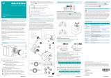
The window “Connection properties” shown below will appear. Click on «Properties» button.
The window “Connection Parameter – TCP/IP” shown below will appear. Now, you can change the
IP address.
Click on «OK» to validate, then on «File» and «Exit» to close the project.
This procedure allows changing the TCP/IP parameter to communicate with the Master Station
MS202 unit labeled “PLC 1”. To change the TCP/IP parameter to communicate with the Master Sta-
tion MS202 unit labeled “PLC 2” follow the same procedure but, this time, select “ProgE2”.
Note: Before changing the TCP/IP parameters you must know the IP address of each unit, so refer
to NR1177 – Master Station MS202 Technical Manual.
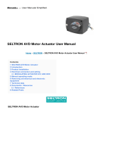
3 SETTING UP yOUR PC WORkSTaTION
To run the Master Station MS202 application click right on the WinCC icon on the taskbar.
Then select Activate the project will run the application.
3.1 LaNGUaGE
Language can be chosen amongst the following list: English, French, Spanish, German and Italian.
Any type of user’s accounts has access to this setting (refer to part 5.1. Log in access).
From any pages you have access to the Toolbar on the bottom of the screen (for more details about
the navigation refer to section 5. PC Workstation). Click on the green arrow on the left bottom corner
to display the “Language Selection” icon.
A window will be displayed. Select the language you want.
“Language Selection” icon

6 7
On the top of the “Setting date and clock” window there is the current date and clock. You can
change these parameters on the left of the window and press Enter on the keyboard to confirm
your choice. Then, to validate the change click on the «Update Clock» button.
Now, the entire system (Touch screens, Internal Web pages and the PC) is configured with the new
parameters. Click on «Cancel» to go back to the main picture.
3.3 MaNaGEMENT Of USER’S aCCOUNTS
You can restrict access to the Master Station according to user’s profile. Indeed there exist four
types of accounts all secured by a password, possibilities of each account are described in Annex
User’s account
• User: You can only consult information about the Master Station and the actuators connected to it.
• Super-user: Like with the user account, you can consult information about the Master Station and
the actuators connected to it. But you can also command the actuators.
• Maintenance: You can consult information about and set up the Master Station, and have full
access to actuators (piloting and setting up).
• Administrator: This account is dedicated to the management of user’s accounts.
To create a user’s account you must be logged in with an Administrator account (refer to section
5.1. Log in access).
From any pages you have access to the Toolbar on the bottom of the screen (for more details about
the navigation refer to section 5. PC Workstation). Click on the green arrow on the left bottom corner
to display the “User’s account” icon.
The “User Administrator” window is open and it allows you to create a user’s account.
Wait a few seconds and the change will be effective.
3.2 CLOCk
You can set up date and time only if you are logged in to the Maintenance account (refer to section
5.1. Log in access).
From the “Main Picture” window, click on the “Update date and time” button to access to the “Setting
date and clock” window.
« Update date
and clock »
button
“User’s account” icon

8 9
On the left of the window there are the four kinds of user’s account: Administrator, Maintenance,
SuperUser and User. To add an account select the type of account and click on “User” then on “Add
user…”.
For information, authorizations per type of user’s account are presented below:
Administrator Maintenance SuperUser User
4 SETTING UP yOUR aCTUaTORS
4.1
aCTIvaTE yOUR aCTUaTORS
The first thing you have to do is to activate the actuator on the Master Station to establish the com-
munication between those. There, before activating the actuator, make sure it is correctly cabled
and connected and its slave address is correctly set up.
Note : The number of the valve you will activate must correspond to the slave address minus 2 (For
example the valve number 1 will have 3 for slave address, the valve number 2 will have 4 for slave
address...).
To activate an actuator you must be logged in with a Maintenance account (refer to section 5.1.
Log in access).
From any windows click on the “Valves Status” button on the top of the screen, then on “Valves
1 -60” or “Valves 61 – 120” on the “Valves Activity” column, depending on the actuator you want
activate.
The “Valves activity page 1 or 2”, depending on the actuator you want to activate, is displayed and
you can see the status of each actuators.
If the actuator is activated, the “Active Valve” inscription and the “Deactivate” button are displayed
on the right of the valve number. If the actuator is inactived, the “Inactive Valve” inscription and the
“Activate” button are displayed on the right of the valve number.
To activate an actuator, click on the corresponding “Activate” button.
The communication with your actuator is now established and you have access to all functionna-
lities of the actuator.
Now, when you come back on the Valve Status screen (refer to section 6.2. Actuators Status) you
get information about the actuator. If there is communication fault it will be displayed. In such case,
make sure Profibus is correctly cabled and slave address is correctly set up, then deactivate and
reactivate the actuator.
The “Next page” button allows you to access directly to the “Valves activity page 2”.
« Valves Status »
button
“Valves 1 -60” &
“Valves 61 – 120”
on the “Valve
Activity” column
« Inactive Valve »
inscription
« Active Valve »
inscription
« Deactivate»
button
« Activate»
button
« Next page »
button

10 11
The “Last page” button allows you to access directly to the “Valves activity page 1”.
4.2 RENaME yOUR aCTUaTORS
To change the valve name you must be logged in with a Maintenance account (refer to section 5.1.
Log in access).
From any windows click on the “Valves Status” button on the top of the screen, then on “Valves 1
-60” or “Valves 61 – 120” on the “Valves Tag” column, depending on the actuator you want change
the name of.
The “Valves Tag page 1 or 2”, depending on the actuator you want to change the name of, is dis-
played. To change a valve name click on the current tag and enter the new name, then press “Enter”
on your keyboard to validate the change.
« Last page »
button
The “Next page” button allows you to access directly to the “Valves Tag page 2”.
The “Last page” button allows you to access directly to the “Valves Tag page 1”.
4.3 SET UP yOUR aCTUaTOR
To set up an actuator you must be logged in with a Maintenance account (refer to section 5.1. Log
in access). If you are logged in with a User or SuperUser account you have access to these pages
but you cannot change any values.
Once you selected the valve you want change a parameter of (refer to part 6.1.Actuator selection),
click on «Change».
4.3.1 SET UP COMMaNDS
On the « Change » index of the « Valve status » select the “Commands” index.
« Valves Status »
button
“Valves 1 -60” &
“Valves 61 – 120”
on the “Valves
Tag” column
« Next page »
button
« Last page »
button

12 13
You can allocate the auxiliaries commands to the following functions:
• LOCAL/REMOTE: Replace the local/remote selector on the actuator and, under remote
control conditions, authorize either local control or remote control.
• LOCAL+REMOTE/REMOTE: This function has the same role as the previous one, but local
and remote control can be authorized simultaneously.
• PROHIBITING LOCAL CONTROL: Prohibiting local control is controlled remotely This func-
tion prohibits local opening and closing controls and authorizes remote control even if
the actuator selector is placed on local control.
• PROHIBITING OPENING/CLOSING: This control is used for preventing the actuator from
starting or stopping
• AUTO / ON-OFF: For an actuator used in modulating mode with a positioning function, a
command can be selected by position set-point (equivalent to the 4/20mA signal) or by
opening, closing or stop controls. The auto/on-off control is used for changing from one
control mode to another.
• CLOSING / OPENING / EMERGENCY SHUTDOWN: The ESD (Emergency Shut Down) is an
emergency remote command that has priority over the other commands. Depending on
the type of operation for which the valve is to be used, this emergency command can be
opening, closing or stopping in an intermediate position. The ESD command is assigned
to a Modbus command for auxiliary command 1 and to a wired link (separate cabling) for
auxiliary command 2.
Note: The cabled ESD has priority over the Modbus ESD. Emergency control is not pos-
sible when the switch is in the OFF position.
• PARTIAL MOVEMENT: This control carries out an automatic test to ensure that the ac-
tuator is still operational. The test consists of manoeuvering the actuator over a part of
its course. The starting position as well as the percentage of movement can be set. An
alarm is given off if the test has not been carried out within a predetermined time.
A priority can be selected between the opening command and the closing command.
In standard there is no priority between opening and closing.
Priorities are used for:
- Reversing the direction of movement during operation without passing via a stop com-
mand. In this case, a priority for opening or a priority for closing must be configured.
- Giving priority to a direction of rotation: If the actuator receives two simultaneous ope-
ning and closing orders and an opening priority has been selected, the actuator will go
rotate for opening.
« Commands »
index
« Change » index
« Apply » button
To change a parameter, click on the current value to display a drop-down list, then select the au-
xiliary command or the priority command you want and click on “Apply” to validate your change.
Note: if there is a loss of communication between the two PLC only the signals which come from
actuators connected to the primary PLC will be refresh. Similarly, it will only be possible to control
actuators connected to the primary PLC.
4.3.2 SET UP TORQUE
On the « Change » index of the « Valve status » select the “Torque” index.
On this window you can change the torque limitations and the closing mode.
There are four torques parameters:
- Close (%) : limits torque during closing
- Close tight (%): the torque applied on the valve seat may not be the same as the torque
limit during the closing movement.
- Open breakout (%): the torque limit to unseat the valve may be different from – generally
higher than - the torque limit during the opening movement.
- Open (%): limits torque during opening movement.
For information the value of these four torque types measured during the last electric actuation are
displayed as shown below.
Finally you can change the closing mode.
There are three possible values:
- On position
- Closing on torque
- Opening and closing on torque
To change a torque parameter click on the current value and enter a new value, it must be between
40% and 100%. Press on Enter on the keyboard to confirm your choice.
Note: Change the torque settings must be doing with full knowledge of the fact.
To change the closing mode click on the current value to display a drop-down list, then select the
mode you want.
Click on “Apply” to validate your change.
« Torque » index
« Change » index
« Apply » button

14 15
4.3.3 DaTaShEET
On the « Change » index of the « Valve status » select the “Datasheet” index.
On this window you can change the actuator tag. You can also select a fail-safe position that
the actuator will reach in case of loss of communication with the Master Station MS202. You can
choose among the following positions:
ON POSITION: The actuator stays in position.
OPENING: The actuator runs in the opened direction.
CLOSING: The actuator runs in the closed position.
To change the actuator tag, click on the current value and enter a new value.
To change the fail safe position click on the current value to display a drop-down list, then select
the position you want.
Click on “Apply” to validate your change. change, click on «Cancel» to go back to the «Valve Selec-
tion» page.
UTILISaTION
5
PC WORkSTaTION
With the PC workstation it is possible to activate and configure an actuator, to pilot your actuator, to check its
activity and its characteristics and consult its torque curves.
You can consult the status of the Master Station MS202 or configure it.
In addition, all the messages and the alarms about the Master Station MS202 and about the actuators are
saved in the PC workstation.
PC Workstation layout:
(*) Check menu is described in the next board.
« Datasheet »
index
« Change » index
« Apply » button

16 17
This window appears when you start the Master Station application, but there are two others way
to display it.
On the top right corner of the window there is the label of the current session. Click on it and the
“System Login” window will appear.
You can also click on the “Login” icon on the bottom toolbar.
This allows you to change the accounts from any page.
5.2 MENU aND TOOLbaRS
Alarm banner:
On the top of the window there is an alarm banner which displays actuator’s and Master Station’s
faults. Alarms are classified in two categories:
- Alarm: means that actuator is not available because of fault, consequently you cannot
control it (red line).
- Warning: means there is a fault but the actuator is still available, then you can control it
(yellow line).
Date: The date when the fault arrived.
Time: The time when the fault arrived.
Origin: It specifies if the fault concerns an actuator or the Master Station.
Designation: It is the fault description.
: alarm arrived
: alarm arrived and gone
Status: It means that fault has arrived, left or acknowledged.
Acknowledgement: This button allows you to acknowledge the fault, so the message disappears
from the alarm banner.
Menu:
On the top of the window there is a menu which allows you to access directly to any pages.
There is four drop-down lists: Main picture, Master Station, Valves Status and History. To display
these, click on the arrow on the right.
To run the Master Station MS202 application click right on the WinCC icon on the taskbar.
Then select Activate the project will run the application.
5.1 LOG IN aCCESS
You can restrict access to the Master Station according to user’s profile. Indeed there exist four
types of accounts all secured by a password, possibilities of each account are described in Annex
User’s account.
• User: You can only consult information about the Master Station and the actuators
connected to it.
By default: Login: User Password: 333333
• Super-user: Like with the user account, you can consult information about the Master
Station and the actuators connected to it. But you can also command the actuators.
By default: Login: SuperUser Password: 222222
• Maintenance: You can consult information about and set up the Master Station, and have
full access to actuators (piloting and setting up).
By default: Login: Main Password: 111111
• Administrator: This account is dedicated to the management of user’s accounts.
By default: Login: Admin Password: 321321
In order to log in, you must enter a login and a password (described before) in the “System Login”
window shown below.
Date Time Origin Designation Status Acknowledgement
Current session
« Login » icon

18 19
Last view: this button allows you to go back to the last view which is displayed.
Next view: this button allows you to go back to the next view which is displayed.
Store a view: this button allows you to store a view so that you can restore it later.
Restore a view: this button allows you to restore the view which is stored before.
View information: this button allows you to display some information about the current window.
Toolbar n°2:
Toolbar n°1: this button allows you to display Toolbar n°1.
Language selection: this button allows you to display the “Language selection” window (refer to
section 3.1. Language).
User’s accounts: displayed only if you are logged in with an administrator account. This button
allows you to manage the user’s accounts (refer to section 3.3. Management of user’s account).
Exit runtime: displayed only if you are logged in with a maintenance account. This button allows you
to exit to the Master Station MS202 application.
6 aCTUaTORS
In this section we will describe what the Master Station MS202 allows you to do with the actuators.
6.1 aCTUaTORS SELECTION
To access to the “Valves Status” window you must follow the instructions described in section 5.2.
Menu and toolbar or, from any window click on the “Valves Status” button on the top of the screen,
then on “Valves 1 -30”, “Valves 31 -60”, “Valves 61 -90” or “Valves 91 – 120” on the “Valves Status”
column, depending on the actuator you want consult.
Then, a list of thirty valves is displayed, and you can see status of active valves.
Main picture drop-down list:
You have a direct access to the “Set date and clock”
window, by clicking on the corresponding button.
Master Station drop-down list:
You have a direct access to the “Master Station Confi-
guration” window, by clicking on the
corresponding button.
Valves Status drop-down list:
You have a direct access to the four “Valves Status”
windows, to the two “Valves Name” windows and to
the two “Activity valve” windows, by clicking on the
corresponding buttons.
History drop-down list:
You have a direct access to the “Value History”, to the
“Alarm History” and to the “Message History” win-
dows, by clicking on the corresponding buttons.
Toolbar n°1:
Toolbar n°2: this button allows you to display Toolbar n°2.
Log in window: this button allows you to display the “Log in” window (refer to section 5.1. Log in
access).
Events report: this button allows you to display all the alarms presented in the alarm line on the top
of the screen (refer to section 6.5.2. Alarm and message history).
Browsing arrows: these buttons allow you to browse between the pages according to the PC
Workstation menu layout described in section 5.PC Workstation.
Language selection User’s accounts Exit runtimeToolbar n°1
Arrows allowing displaying a drop-down list
Log in window Browsing Arrows
Restore a viewStore a view
Events report Last view Next view View informationToolbar n°2
« Valves Status »
button
“Valves 1 -30”,
“Valves 31 -60”,
“Valves 61 -90” &
“Valves 91 – 120”
on the “Valve
Status” column

20 21
Indications description:
• Valve symbol: this symbol can be in four colors:
- White means that the valve is not active
- Green means that the valve is open
- Red means that the valve is closed
- Yellow means that the valve is in an intermediary position
• Position: this is the current position of the valve; value is between 0% and 100%
• Valve number: it is the number of the valve; value is between 1 and 120
• Valve tag: it is the landmark of the valve (refer to section 4.2. Rename your actuator)
• Fault symbol: this symbol means that the valve is not available for one of the following
reasons:
- The selector is in Local or Off position
- The torque limiter is activated
- Motor thermal overload activated: The actuator will be available again as soon
as the motor has cooled down.
- Phase loss fault: Only in 3-phase mode, one phase is missing. No start-up
allowed.
- Valve too hard: Opening or closing is incomplete as the torque is too high.
- Rotation direction fault: Direction of rotation non-compliant in opening or clo-
sing mode.
- Actuator jam alarm: The actuator is jammed when either opening or closing.
- Torque or position sensor fault: The actuator no longer receives any
information from the torque or position sensor.
- Partial movement Fault: The partial movement test has detected a fault.
Position
Fault symbol
Valve symbol
Valve number
Valve Tag
Buttons description:
• : valve symbol is also a button which allows you to access to its status window.
• : you can enter the number of an active valve in the purple box (press «Enter» on the
keyboard to validate the valve number) to access to it by clicking on “Valve status”
button.
• : this button allows you to display the last “Valves Status” windows.
• : this button allows you to display the next “Valves Status” windows.
6.2 aCTUaTORS STaTUS
After a valve was selected on a “Valves Status” window, its “Actuator status” window is displayed.
You can find on this screen the current valve position and torque, the Remote/Local selector position
and, in case of fault, fault description.
Indications description:
• : It means that the Selector of the actuator is in OFF position.
• : It means that the Selector of the actuator is in Local position.
• : It means that the Selector of the actuator is in Remote position.
• : this is the current position of the valve; value is between 0% and 100%
• : this is the current torque of the valve; value is between 10% and 150%

22 23
• : It means that the actuator is open.
• : It is displayed when the actuator is running in the open direction.
• : It means that the actuator is closed.
• : It is displayed when the actuator is running in the close direction.
• In case of fault, a description is given on the right of the window. See below a list of the faults
which can be displayed:
- Motor thermal overload activated: The actuator will be available again as soon as the
motor has cooled down.
- Phase loss fault: Only in 3-phase mode, one phase is missing. No start-up allowed.
- Rotation direction fault: Direction of rotation non-compliant in opening or closing mode.
- Torque sensor fault: The actuator no longer receives any information from the torque
sensor.
- Position sensor fault: The actuator no longer receives any information from the position
sensor.
- Non-redundant com.: Communication between the Master Station MS202 and the
actuator is no longer redundant.
- Loss of com.: Communication between the Master Station MS202 and the actuator is cut
off.
- Overtravel alarm: Position overshoot > 5% after motor shut down.
- Motor jammed on opening: The motor locked in the opening direction.
6.3 COMMaND yOUR aCTUaTOR
Once the “Actuator status” window is displayed, click on the “Control” index to display the “Control”
window. From this page it is possible to control the actuator, but only if you are logged in with a
Maintenance or a SuperUser account.
Depending on auxiliary command “On – Off / Auto”, control window can have two different ap-
pearances. But in each case you can find the current position of the valve, a fault light and the
auxiliaries’ commands.
Fault light is displayed if the actuator is not available for one of the following reasons:
- The selector is in Local or Off position
- The torque limiter is activated
- Motor thermal overload activated: The actuator will be available again as soon as the
motor has cooled down.
- Phase loss fault: Only in 3-phase mode, one phase is missing. No start-up allowed.
- Valve too hard: Opening or closing is incomplete as the torque is too high.
- Rotation direction fault: Direction of rotation non-compliant in opening or closing mode.
- Actuator jam alarm: The actuator is jammed when either opening or closing.
- Torque or position sensor fault: The actuator no longer receives any information from the
torque or position sensor.
- Partial movement Fault: The partial movement test has detected a fault.
To know which fault is in progress click on «Status» index to get the fault list.
For more information about auxiliaries’ commands refer to section 4.3.1. Set up Commands.
On – Off control:
Here you can control the actuator in opening and closing direction with the “Open” and “Close”
buttons. It is possible to stop the actuator in mid travel with “Stop” button.
Auto control:
To switch to the «Auto» command, «ON-OFF/Auto»must be affected to an auxilliary command, then
click on «Auxiliary Command 1 or 2.
Here you can control the actuator in opening and closing direction by setting a position order and
by validating your set by clicking on “Apply”, then the actuator will run to the position order and
stop to this position.
6.4 ChECk
Once the “Actuator status” window is displayed, click on the “Check” index to displayed the “Check”
window. From this page it is possible to see a lot of data about the actuator like its activity, its
commands configuration or its torque setting.
6.4.1 aCTIvITy
When you click on the “Check” index the “Activity” screen is displayed by default, but you can also
click on “Activity” index on the bottom of the window.
Current position
of the valve
Close buttonOpen button
Auxiliaries’
commands 1 and 2
Fault light
becomes red in
case of fault
Valve closed light
Stop button
Valve opened light
Current position
of the valve
Apply buttonPosition order
Auxiliaries’
commands 1 and 2
Fault light
becomes red in
case of fault
Valve closed lightValve opened light

24 25
On this screen you can find the number of starts during the last 12 hours, the number of starts
since actuator manufacturing and since the last reset. You can also see the operating time since the
actuator manufacturing and since last reset.
6.4.2 COMMaNDS CONfIGURaTION
From “Check” window click on “Commands” index to display the commands configuration of the
actuator.
On this window you can see the configuration of the auxiliaries’ commands and check if a priority is
given to opening command or to closing command.
Auxiliaries’ commands can be allocated to the following functions:
• LOCAL/REMOTE: To replace the local/remote selector on the actuator and, under remote
control conditions, is used to authorize either local control or remote control.
• LOCAL+REMOTE/REMOTE: This function has the same role as the previous one, but local
and remote control can be authorized simultaneously.
• PROHIBITING LOCAL CONTROL: Prohibiting local control is controlled remotely This func-
tion prohibits local opening and closing controls and authorizes remote control even if
the actuator selector is placed on local control.
• PROHIBITING OPENING/CLOSING: This control is used for preventing the actuator from
starting or stopping
« Check » index
« Activity » index
« Check » index
« Commands »
index
• AUTO / ON-OFF: For an actuator used in modulating mode with a positioning function, a
command can be selected by position set-point (equivalent to the 4/20mA signal) or by
opening, closing or stop controls. The auto/on-off control is used for changing from one
control mode to another.
• CLOSING / OPENING / EMERGENCY SHUTDOWN: The ESD (Emergency Shut Down) is an
emergency remote command that has priority over the other commands. Depending on
the type of operation for which the valve is to be used, this emergency command can be
opening, closing or stopping in an intermediate position. The ESD command is assigned
to a Modbus command for auxiliary command 1 and to a wired link (separate cabling) for
auxiliary command 2.
Note: The cabled ESD has priority over the Modbus ESD. Emergency control is not pos-
sible when the switch is in the OFF position.
• PARTIAL MOVEMENT: This control carries out an automatic test to ensure that the ac-
tuator is still operational. The test consists of manoeuvering the actuator over a part of
its course. The starting position as well as the percentage of movement can be set. An
alarm is given off if the test has not been carried out within a predetermined time.
A priority can be selected between the opening command and the closing command.
In standard there is no priority between opening and closing.
Priorities are used for:
- Reversing the direction of movement during operation without passing via a stop com-
mand. In this case, a priority for opening or a priority for closing must be configured.
- Giving priority to a direction of rotation: If the actuator receives two simultaneous ope-
ning and closing orders and an opening priority has been selected, the actuator will go
rotate for opening.
6.4.3 TORQUE PROfILE
From “Check” window click on “Torque” index to display the torque configuration of the actuator.
On this window you can see the torques’ setting, the closing mode and the torque curves.
There are four torques parameters:
- Close (%) : limits torque during closing
- Close tight (%): the torque applied on the valve seat may not be the same as the torque
limit during the closing movement.
- Open breakout (%): the torque limit to unseat the valve may be different from – generally
higher than - the torque limit during the opening movement.
- Open (%): limits torque during opening movement.
« Check » index
« Torque » index

26 27
For information the value of these four torque types measured during the last electric actuation are
displayed.
Finally you can find the closing mode, there are three possible values:
- On position
- Closing on torque
- Opening and closing on torque
You can also see close torque curve and open torque curve of the last electric actuation.
So click on “Close torque curve” or on “Open torque curve” to display it.
6.4.4 DaTaShEET
From “Check” window, you must click on “Datasheet” index to display technical information about
the actuator.
On this page you can consult the following parameters:
The Actuator number
The Actuator tag
The Operating class (‘On-Off’, ‘Modulating Class II’ or ‘Modulating Class III’)
The type of the Motor supply (‘3 phases’ or ‘1 phase or DC)
The Nut thread in millimeter (0 means that is not a linear actuator)
The necessary time to detect the motor jammed (in seconds)
The Reverse delay time between a closing and an opening operation (in milliseconds)
The Gear box reduction
« Open torque
curve » index
« Close torque
curve » index
« Datasheet »
index
« Check » index
The Stroke (‘Turns’, ‘Degrees’ or ‘mm’)
The Intelli+ software version
The Manufacturing date
The actuator Profibus address (3 to 252)
The Fail safe position (‘Open’, ‘Close’ or ‘On position’)
6.4.5 hISTORIC
From “Check” window, you must click on “Historic” index to display the histories of position, torque,
commands, indications or alarms.
By default the position’s history is displayed.
hISTORIC Of POSITION aND TORQUE are represented by a curve according to the time.
Above the curve there is a toolbar which offers many functions.
1: theses buttons allow you to go from the first recording to the last, only if you are doing pause
2: theses buttons allow you to zoom in the curve area
: zoom area
: zoom +/-
: zoom time axis +/-
: zoom valve axis
3: this button allows you to move the curve from down to up and from left to right
4: this button allows you to move the axes range
5: this button allows you to change the way to display the curve. After clicking on this button the
“Time – Selection” window appears and you can select display type among “Time range”, “Start and
end time” and “Number of measurement point”.
Time range
If you select “Time range” setting you must select time scale to display on the window.
You can select a gauge among “500ms”, “1 second”, “1 minute”, “1 hour” and “1 day”, and a multiplier
(for example 12 x 1 hour to display the curve on the last 12 hours).
1 2 3 4 5 6 7
Multiplier
Gauge
« Time range »
setting

28 29
6.4.5.2 TORQUE
From “Historic” window, you must click on “Torque” index to display the history of torque.
hISTORIC Of COMMaNDS, SIGNaLS aND aLaRMS are represented by a list. Above the
list there is a toolbar which offers many functions.
1: Select dialog: this button allows you to select the type of information that you want to display,
by default all information is displayed. If you want to make a selection, click on it, then a “Selection”
window is displayed.
To enable or disable a filter you must tick on it or not.
To add a new filter click on “New”. Then label the filter and select a criterion in the drop-down list.
Depending on your choice you must select an operand and a setting. For example, if you select
“Event” in the criterion down-drop list, the operand will be “equal to” and the settings will be, for
example, “Close command”, “Stop command” or “Actuator running” depending of the history window.
Start and end time
If you select “Start and end time” you must select the Start time and the end time, then it will be
this duration which will be displayed on the window.
Number of measurement points
If you select “Number of measurement points” you must select the number of points you want to be
displayed (for example if you choose 120 points, it will be the last 120 measurement points which
will be displayed).
6: this button allows you to do “Pause”
7: this button allows you to print the curve
To enable or disable a filter you must tick on it or not.
6.4.5.1 POSITION
From “Historic” window, you must click on “Position” index to display the history of position.
Start time
End time
« Start and end
time » setting
« Number of
measurement
points » setting
Number of
measurement
points
1 2 3 4 5 6
« Check » index
« Position » index
« Historic » index
« Check » index
« Torque » index
« Historic » index
« New » button
Filter enable
Filter disable
Filter setting
Filter operand
Filter name
Filter criterion

30 31
If you create a filter with “criterion = Event”, “Operand = equal to” and “Setting = Close command”;
only such messages will appear into the list.
2: this button allows you to print the list.
3: Export data: this button allows you to export the message list as a table. Click on it, the “Export
data” window is displayed and you must enter a filename. Select the destination directory and click
on “OK”.
4: this button allows you to go to the first message of the list.
5: this button allows you to go to the last message of the list.
6: Sort dialog: this button allows you to sort the messages with four criterions. For each criterion
you can associate to it ascending or descending parameter.
6.4.5.3 COMMaNDS
From “Historic” window, you must click on “Commands” index to display the history of the com-
mands.
On this window you can find the following messages:
- Stop command
- Open command
- Close command
- Auxiliary command 1
- Auxiliary command 2
6.4.5.4 SIGNaLS
From “Historic” window, you must click on “Indication” index to display the history of the signals.
On this window you can find the following messages:
- Actuator is opening
- Actuator is closing
- Actuator is running
- Valve open
- Valve closed
- Stop in mid travel
- Selector in local position
- Selector in remote position
- Selector in off position
- Valve active
File name
Destination
directory
The four criterions
Ascending or
descending mode
« Check » index
« Commands »
index
« Historic » index
« Check » index
« Indication »
index
« Historic » index

32 33
6.5 hISTORy MENU
To access to the “Data history”, “Alarm history” or “Message history” window you must follow the
instructions describe in section 5.2. Menu and Toolbars or, from any window click on the “History”
button on the top of the screen.
6.5.1 DaTa hISTORy
To access “Data history” you must click on “History” button on the top of the screen and then on
“Data history”.
On this window you can check the position and the torque of any active valve from the moment it
will be activated until now.
So, enter the number of the valve you want check and press on “OK”.
Above these curves there is a toolbar which offers you many functions and which is described
below.
- Valve inactive
- Channel is primary
- Channel is backup
- Partial stroke in progress
- Handwheel action
- Power on
6.4.5.5 aLaRMS
From “Historic” window, you must click on “Alarms” index to display the history of the alarms.
On this window you can find the following messages:
- Actuator fault
- Torque sensor power supply fault
- Position sensor supply fault
- ESD activated
- Motor locked in opening direction
- Motor locked in closing direction
- Loss of communication
- Loss of signal
- Valve jammed
- Rotation direction fault when closing
- Rotation direction fault when opening
- Intelli+ communication fault
- Loss of phase fault
- Motor thermal overload
- Torque limiter action in closing direction
- Torque limiter action in opening direction
- Non redundant communication
- Too many starts
- Actuator pumping
- Overtravel
- Partial stroke fault
- Auxiliary 24V fault
- Activity memory fault
- Configuration memory fault
- Base memory fault
- Battery low
« Check » index
« Alarms » index
« Historic » index
« Data History »
button
« History » button
« Message
History » button
« Alarm History »
button
Valve number
Position
history
Torque
history
« Ok » button
1 2 3 4 5 6 7

34 35
6: this button allows you to do “Pause”
7: this button allows you to print the curve
6.5.2 aLaRM aND MESSaGE hISTORy
Alarm and message history are represented by lists. Above these lists there is a toolbar which offers
you many functions and which is described below.
1: Message List: it allows you to display only the current non-acknowledged alarms
2: Short-term archive list: it allows you to display around 50 messages
3: Long-term archive list: it allows you to display around 1000 messages
4: Single acknowledgement: it allows you to acknowledge only one alarm
5: Group acknowledgement: it allows you to acknowledge all the non-acknowledged alarms
6: Select dialog: this button allows you to select the type of information that you want to be dis-
played, by default all information is displayed. Therefore, if you want make a selection, click on it,
and a “Selection” window will appear.
To enable or disable a filter you must tick on it or not.
1: theses buttons allow you to go from the first recording to the last, only if you are doing pause
2: theses buttons allow you to zoom in the curve area
: zoom area
: zoom +/-
: zoom time axis +/-
: zoom valve axis
3: this button allows you to move the curve from down to up and from left to right
4: this button allows you to move the axes range
5: this button allows you to change the way to display the curve. After clicking on this button the
“Time – Selection” window appears and you can select display type among “Time range”, “Start and
end time” and “Number of measurement point”.
Time range
If you select “Time range” setting you must select time scale to display on the window.
You can select a gauge among “500ms”, “1 second”, “1 minute”, “1 hour” and “1 day”, and a multiplier
(for example 12 x 1 hour to display the curve on the last 12 hours).
Start and end time
If you select “Start and end time” you must select the Start time and the end time, then it will be
this duration which will be displayed on the window.
Number of measurement points
If you select “Number of measurement points” you must select the number of points you want to be
displayed (for example if you choose 120 points, it will be the last 120 measurement points which
will be displayed).
Multiplier
Gauge
« Time range »
setting
Start time
End time
« Start and end
time » setting
« Number of
measurement
points » setting
Number of
measurement
points
91 2 3 4 5 6 7 8 10 11 12 13 14 15 16 17
Filter enable
« New » button
Filter disable

36 37
16: Connect backup
17: Disconnect backup
6.5.2.1 aLaRM hISTORy
To access “Alarm history” window you must click on “History” button on the top of the screen and
then on “Alarm history”.
On this window you can check all the alarms about Master Station MS202 and the actuators.
Alarms are classified in two categories:
- Alarm: means that actuator is not available because of fault, and as a consequence you
cannot control it (red line).
- Warning: means there is a fault but actuator is still available and you can control it (yel-
low line).
To add a new filter click on “New”. Then label the filter and select a criterion in the drop-down list.
Depending on your choice, you must select an operand and a setting. For example, if you select
“Event” in the criterion down-drop list, the operand will be “equal to” and the settings will be, for
example, “Close command”, “Stop command” or “Actuator running” depending on the history window.
Thus, if you create a filter with “criterion = Event”, “Operand = equal to” and “Setting = Close com-
mand”; and if you enable it, only this kind of messages will appear into the list.
7: this button allows you to print the list.
8: Export data: this button allows you to export the message list as a table. Click on it, “Export data”
window is displayed. Then, enter a filename, select the destination directory and click on “OK”.
9: Auto-scroll: it allows you to select one or many lines
10: it allows you to go to the first message
11: it allows you to go to the previous message
12: it allows you to go to the next message
13: it allows you to go to the last message
14: Make a comment: it allows you to make a comment about an alarm
15: Sort dialog: this button allows you to sort the messages with four criterions. For each criterion
you can associate to it ascending or descending parameter.
File name
Destination
directory
Filter name
Filter setting
Filter operand
Filter criterion
The four criterions
Ascending or
descending mode

38 39
On this window you can find the actuator faults described in section 6.4.5.5.Alarms.
Concerning Master Station MS202 you can find the followings alarms:
- Communication fault between Units
- Communication fault between Unit 1 and Web interface
- Communication fault between Unit 2 and Web interface
- Communication fault between PC and Unit 1
- Communication fault between PC and Unit 2
6.5.2.2 MESSaGE hISTORy
To access to the “Message history” window you must click on “History” button on the top of the
screen and then on “Message history”.
In this window you can check all the messages about the valves. Messages are classified in two
categories:
- Process status: which corresponds to the signals history described in section 6.4.5.4.
Signals. Commands but for all the active valves at a time (purple line).
- Operator command: which corresponds to the command history described in section
6.4.5.3. Commands but for all the active valves at a time (blue line).
aNNEx - USER’S aCCOUNT
• User:
Master Station MS202:
It is possible to change the language, to consult the status of the Master Station and the alarms.
It is not possible to change the network configuration, date and time, or to create or change a user’s
account.
Actuators:
It is possible to consult the status of a valve, to check the valve configuration, its characteristics, its
activity and its torque curves.
It is not possible to activate/deactivate a valve, to change the actuator configuration and to com-
mand the actuator.
• Super-user:
Master Station MS202:
It is possible to change the language, to consult the status of the Master Station and the alarms.
It is not possible to change the network configuration, date and time, or to create or change a user’s
account.
Actuators:
It is possible to consult the status of a valve, to check the valve configuration, its characteristics, its
activity and its torque curves. It is also possible to command the actuator.
It is not possible to activate/deactivate a valve or to change the actuator configuration.
• Maintenance:
Master Station MS202:
It is possible to change the language, to consult the status of the Master Station and the alarms.
It is also possible to change the network configuration, date and time.
It is not possible to create or change a user’s account.
Actuators:
It is possible to consult the status of a valve, to check the valve configuration, its characteristics, its
activity and its torque curves.
It is also possible to activate/deactivate a valve, to change the actuator configuration and to com-
mand the actuator.
/