Page is loading ...

Providing sustainable energy solutions worldwide
178 058 64-6 P93783 2023-08-28
Installation and maintenance instruction
B 80i-3R FAME/RME J/K
LMV 37
E 6N CK
Translation of the original instructions.

2Bentone
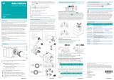
example Beispielexempel
352011030141
Designation
Type
Model
Serial no.
Motor supply
Main supply
MADE IN SWEDEN BY
LIGHT OIL 35-90kW 1,25-6,0 cSt 7-14bar
BF 1 KS 76-24
BF 1
BF 1 KS 76-24
1234567
1~230V 1,0A 50Hz IP 20
Man.Year 2019
Cap. Min-Max
3
?
1
-sv
1. Manualer på övriga språk
2. www.bentone.com\
nedladdning
eller scanna QR-koden.
3. Skriv in brännarens
artikelnummer som nns på
din
typskylt (se bild) och välj ditt
språk.
Detaljerad ecodesign
information kan laddas ner
på:
www.bentone.com/
ecodesign.
-en
1. Manuals in other languages
2. www.bentone.com\
download
or scan QR-code.
3. Enter the burner`s article
number on your data plate
(see picture) and select
language.
Detailed ecodesign
information can be
downloaded at:
www.bentone.com/
ecodesign.
-da
1. Manualer på andre sprog
2. www.bentone.com\
download eller scan QR-
koden.
3. Indtast brænderens
artikelnummer, der ndes
på typeskiltet (se billede), og
vælg dit sprog.
Detaljerede oplysninger om
ecodesign kan downloades
på: www.bentone.com/
ecodesign.
-fr
1. Manuels dans d’autres
langues
2. www.bentone.com\
download
ou scannez le code QR.
3. Saisir le numéro d’article
du brûleur sur votre plaque
signalétique (consultez
l’illustration) et sélectionnez
la langue.
Des informations détaillées
sur l’écodesign peuvent être
téléchargées à l’adresse:
www.bentone.com/
ecodesign.
-de
1. Gebrauchsanweisungen in
anderen Sprachen
2. www.bentone.com\
download
oder scannen Sie den QR-
Code.
3. Geben Sie die
Artikelnummer des Brenners
auf Ihrem Typenschild ein,
(siehe Bild) und wählen Sie
die Sprache aus.
Detaillierte Informationen
zum Ecodesign können unter
www.bentone.com/ecodesign
heruntergeladen werden.
2

3 Bentone
Table of contents
1. General Information ............................................................4
1.1 Delivery inspection........................................................................ 4
1.2 Safety ............................................................................................... 4
1.3 General requirements FAME/RME ............................................. 6
2. Technical data .......................................................................7
2.1 Dimensions B 80i-3R .................................................................... 7
2.2 Burner installation ........................................................................ 7
2.3 Workingeld .................................................................................. 8
2.4 Settingfornozzleassemblyandairdamper ......................... 8
2.5 Technicalspecication ................................................................. 9
2.6 Settingofignitionelectrodesandbrakeplate ....................... 9
2.7 Nozzleandpumppressure ......................................................... 9
2.8 Nozzle table ..................................................................................10
2.9 Components ................................................................................. 12
3. Electric equipment ............................................................. 14
3.1 Safety system .............................................................................. 14
3.2 Components ................................................................................. 14
3.3 Wiringdiagram ..........................................................................15
4. LMV37 Automatic control unit .........................................16
4.1 Systemstructure/functiondescription ...................................16
4.2 General information ................................................................... 17
4.3 Technical Data Basic unit LMV37.4... .......................................17
4.4 Connectionandinternaldiagram............................................ 22
5. Operation ........................................................................... 24
5.1 LMV37 automatic control unit ..................................................24
5.2 Listofphasedisplays ................................................................. 26
5.3 Automatic control unit levels .................................................... 27
5.4 Setting the automatic control unit ..........................................32
5.5 10.4 Multistage operation ........................................................35
5.6 Backupandrestore .................................................................... 47
5.7 Faultstatusmessage,displayoferrorsandinfo .................51
5.8 Dispaly message of info ............................................................. 57
5.9 Resetting the automatic control unit ...................................... 58
5.10 Manual output ............................................................................. 59
6. Parameter list .....................................................................61
7. Error code list .....................................................................70
8. Installation ..........................................................................86
8.1 General instructions ................................................................... 86
8.2 Inspectionandmaintenance .................................................... 86
8.3 Start-up ......................................................................................... 86
8.4 Preparing for installation ...........................................................86
8.5 Oildistribution ............................................................................. 86
8.6 Electrical connection .................................................................. 87
8.7 Handlingandliftinginstruction ............................................... 88
9. Mounting ............................................................................89
9.1 Check oil line seals ...................................................................... 89
9.2 Proposedpiperouting .............................................................. 90
9.3 Calculateprepurgetime,Industrialapplications ................ 91
9.4 Example of Basic settings .......................................................... 92
9.5 Nozzleassemblyadjustment–adjustablebrakeplate .......93
9.6 Air setting ..................................................................................... 93
9.7 Setting the air pressure switch ................................................ 94
10. Pump instruction E6NC-1069 ............................................ 95
10.1 Technicaldata .............................................................................. 95
10.2 Components ................................................................................. 95
10.3 Oil connection .............................................................................. 95
10.4 Changingthelter ...................................................................... 95
10.5 Function ........................................................................................ 96
10.6 Preheating pump ........................................................................ 96
11. Service .................................................................................97
11.1 BurnerServiceSchedule,Oil .................................................... 97
11.2 Component replacement intervals ..........................................97
11.3 Combustiondevice .................................................................... 98
11.4 Airdamper ................................................................................... 99
11.5 Replacementofdampermotor,air .......................................100
11.6 Fan ...............................................................................................101
11.7 Replace oil pump ......................................................................102
11.8 Tightnesscheckofsolenoidvalves .......................................103
11.9 Replacement of electrical components ................................ 104
11.10 Vibrations .................................................................................... 105
12. Fault Location ................................................................... 106
12.1 Burner will not start .................................................................. 106
12.2 Burner will not start after normal use ..................................106
12.3 Delayedignition ........................................................................107
12.4 Noise in pump ...........................................................................107
12.5 Pump pressure ..........................................................................108
...................................................109

4Bentone
165 105 01-2 2021-12-07
1. General Information
The burner may only be used for its intended purpose in accordance with the
product’s technical data.
We reserve the right to make design changes and cannot be held liable for any
misprints or typographical errors.
Modifying the design or using accessories or components that have not been
approved by Enertech in writing is strictly prohibited.
This Installation and Maintenance manual:
• is to be regarded as part of the burner and must always be kept near
the installation site.
• must be read prior to installation.
• is intended for use by authorised personnel.
1.1 Delivery inspection
• Make sure everything is delivered and the goods have not been
damaged during transit.
Transport damage must be reported to the shipping company.
• If something is wrong with a delivery, report it to the supplier.
1.2 Safety
- before installation:
• Installation and work on the burner and associated system
components may only be carried out by persons who have undergone
relevant training.
• The product is packaged to prevent damage from occurring when
handled – Handle the product with care! Lifting equipment must be
used to lift larger packages.
• The products must be transported/stored on a level surface in a dry
environment, max. 80% relative humidity, no condensation.
Temperature -20 to +60 °C.
- installation:
• The burner must be installed in accordance with local regulations for
re safety, electrical safety, and fuel distribution.
• The premises must comply with local regulations pertaining to use of
the burner, and must have adequate air supply.
• The installation site must be free of chemicals.
• Fire extinguisher with Class BE recommended.
• Make sure when installing the burner that there is enough space to
service the burner.
• The electrical installation must be professionally carried out in
accordance with current mains electricity regulations and in a
professional manner.
• Make sure that the burner is suitable for the application (see Technical
Data).
• All components must be installed without being bent, twisted or
subjected to mechanical or thermal forces that affect components.

5 Bentone
• Care must be taken by the installer to ensure that no electrical cables
or fuel lines are pinched or otherwise damaged during installation or
service.
• Flame tubes, fan wheels and air dampers, for example, may contain
sharp edges.
- before rst start:
• The burner must not be put into operation without proper safety and
protection devices.
• Permitted ambient temperature during operation -10 to +60 °C. Max.
80% relative humidity, no condensation.
• The surface temperature of the burner’s components may exceed
60 °C.
• Handle with caution – the burner has moving parts, and there is risk
of crushing injuries.
• Seal inspections must be performed during installation and servicing
to prevent leakage.
• tting and installation work has been completed and approved.
• electrical installation has been correctly performed.
• ue gas ducts and combustion air ducts are not blocked.
• all actuators and control and safety devices are in working order and
correctly set.
• If the boiler is equipped with an access hatch, this must be equipped
with a hatch opening switch connected to the burner’s safety system.
• When in operation, the burner’s noise level can exceed 85 dBA – use
hearing protection!
- Operation:
• Carry out all stipulated settings, service and inspection work within
the set time.
• If the oil burner control has a solid red light, contact your installer.

6Bentone
165 405 06 2021-12-07
1.3 General requirements FAME/RME
• The fuel must meet the requirements of standard EN 14214 for FAME.
• The fuel must be stored and used according to the manufacturer’s
instructions. It should typically be used within 6 months of
manufacture. Fuel that is allowed to age loses its oxidation stability
and produces aggressive constituents. These may cause oxidation
damage to components in the oil system. The fuel should be stored in
a cool and dark area.
• The RME tank must be made of metal or dark coloured plastics
approved for the fuel.
• Burners fuelled by FAME (RME) are – and must be – equipped with
parts designed for this fuel. This applies to oil-related parts such as
the pump, solenoid valve, oil lter and hoses.
• Oil hoses must be of high-quality uoride rubber or PTFE intended for
FAME/RME, and the hoses must be tted with re-retardant sleeves in
order to satisfy requirements according to EN-ISO 6806.
• The installation should be performed as a single-pipe system. Copper
should be avoided the fuel system since the fuel and copper have an
oxidising effect on each other.
• Annual cleaning and checking for the presence of water in the tank
should be done to avoid corrosion and microorganisms.

7 Bentone
165 105 80-3
2. Technical data
The burner is intended for:
• Operation in installations according to EN 303, EN 267 and EN 746-2.
Fuels:
• FAME/RME according to EN 14214.
• Fuel oil according to DIN 51603-1.
• Fuel oil A Bio 10 according to DIN 51603-6.
2.1 Dimensions B 80i-3R
* Min. recommended distance to oor.
d1
d2
d3
2.2 Burner installation
2.2.1 Hole patten
Make sure the hole pattern on the boiler is designed for burner ange.
G
H A D
Ø B Ø C
E
F
*I
d1d2d3
ø (205) 225 14 ø (310) 324-390
A Ø B Ø C D E F G H *I
396/696 260 205 730 408 504 472 867 200

8Bentone
2.3 Working eld
2.4 Setting for nozzle assembly and air damper
Basic settings should only be seen as setting values to get burner to start.
Once the burner has started and established ame, it is necessary to adjust the
settings so that they are adapted to the installation and the fuel used.
!Do not exceed working
-4,0
0,0
4,0
8,0
1
2,0
1
6,0
2
0,0
2
4,0
500 1000 1500 2000 2500
mbar
kW
50-211 kg/h
600-2500 kW
160302-768-2
0
10
20
30
40
50
60
70
80
90
100
500 1000 1500 2000 2500
160302-569-2
kW
Air settings
Nozzle assembly
Scale
Burner output

9 Bentone
2.6 Setting of ignition electrodes and brake
plate
Measurements according to EN 15036-1:2006
Alt.1 The noise level of the burner can be reduced by equipping the burner with
silencer. Installation must be done so it does not prevent air supply to the
burner.
Alt.2 The burner’s noise level can be reduced by connecting the burner’s air
intake to the air duct that opens into an appropriate location. Installation
must be done so it does not prevent air supply to the burner.
!*NB It is important that the spark
does not strike against the brake
plate or nozzle.
Nozzle: 45° Solid/semisolid
60° Solid/semisolid
80° Solid/semisolid
Pump pressure: 14 bar (12-16 bar) depending on pump model
2.7 Nozzle and pump pressure
Due to different furnace geometries and capacities, it is not possible to
recommend a nozzle model.
2.5 Technical specication
B 80i-3R
Main supply, Operating 1) 230V, 1~, 0.7A, 50Hz, IP54
Main supply, Motor 230/400V, 19.0/11.0A
Max fuse rating 16A
NOX-class 2
Noise level 96dBA
1) Motor excluded.
a b c d
3.5-4.0 8.0-10.0 2.0-3.0 10.0-13.0
d
a
b
c

10 Bentone
2.8 Nozzle table
The table applies to oil with a viscosity of 4.4 mm2/s (cSt) at a density of 830 kg/m3..
Pump pressure bar
10 11 12 13
Gph kg/h kW Mcal/h kg/h kW Mcal/h kg/h kW Mcal/h kg/h kW Mcal/h
1,00 3,72 44 38 3,90 46 40 4,08 48 42 4,24 50 43
1,10 4,09 48 42 4,29 51 44 4,48 53 46 4,67 55 48
1,20 4,47 53 46 4,68 55 48 4,89 58 50 5,09 60 52
1,25 4,65 55 47 4,88 58 50 5,10 60 52 5,30 63 54
1,35 5,02 59 51 5,27 62 54 5,50 65 56 5,73 68 58
1,50 5,58 66 57 5,85 69 60 6,11 72 62 6,36 75 65
1,65 6,14 73 63 6,44 76 66 6,73 80 69 7,00 83 71
1,75 6,51 77 66 6,83 81 70 7,14 85 73 7,42 88 76
2,00 7,45 88 76 7,81 93 80 8,16 97 83 8,49 101 87
2,25 8,38 99 85 8,78 104 90 9,18 109 94 9,55 113 97
2,50 9,31 110 95 9,76 116 100 10,19 121 104 10,61 126 108
2,75 10,24 121 104 10,73 127 109 11,21 133 114 11,67 138 119
3,00 11,16 132 114 11,71 139 119 12,23 145 125 12,73 151 130
3,50 13,03 154 133 13,66 162 139 14,27 169 146 14,85 176 151
4,00 14,89 176 152 15,62 185 159 16,31 193 166 16,97 201 173
4,50 16,75 199 171 17,57 208 179 18,35 218 187 19,10 226 195
5,00 18,62 220 190 19,52 231 199 20,39 242 208 21,22 252 216
5,50 20,48 243 209 21,47 255 219 22,43 266 229 23,34 277 238
6,00 22,34 265 228 23,42 278 239 24,47 290 250 24,46 302 260
6,50 24,20 287 247 25,37 301 259 26,51 314 270 27,58 327 281
7,00 26,06 309 266 27,33 324 279 28,55 339 291 29,70 352 303
7,50 27,92 331 285 29,28 347 299 30,59 363 312 31,83 377 325
8,00 29,79 353 304 31,23 370 318 32,63 387 333 33,95 403 346
8,50 31,65 375 323 33,18 393 338 34,66 411 353 36,07 428 368
9,00 33,59 398 343 35,14 417 358 63,71 435 374 38,19 453 389
9,50 35,37 419 361 37,09 440 378 38,74 549 395 40,31 478 411
10,00 37,23 441 380 39,04 463 398 40,78 484 416 42,44 503 433
11,00 40,96 486 418 42,94 509 438 44,86 532 457 46,68 554 476
12,00 44,68 530 456 46,85 556 478 48,94 580 499 50,92 604 519
14,00 52,12 618 531 54,65 648 557 57,10 677 582 59,41 705 606
16,00 59,57 706 607 62,46 741 637 65,26 774 666 67,90 805 692
18,00 67,02 795 683 70,27 833 717 73,41 871 749 76,39 906 779
20,00 74,47 883 759 78,08 926 796 81,57 967 832 84,87 1007 865
22,00 81,91 971 835 85,89 1019 876 89,73 1064 915 93,36 1107 952
24,00 89,36 1060 911 93,70 1111 956 97,88 1161 998 101,85 1208 1039
26,00 96,81 1148 987 101,50 1204 1035 106,04 1258 1081 110,33 1308 1168

11 Bentone
The table applies to oil with a viscosity of 4.4 mm2/s (cSt) at a density of 830 kg/m3.
Pump pressure bar
14 15 16 17
Gph kg/h kW Mcal/h kg/h kW Mcal/h kg/h kW Mcal/h kg/h kW Mcal/h
1,00 4,40 52 45 4,56 54 46 4,71 56 48 4,85 57 49
1,10 4,84 57 49 5,01 59 51 5,18 61 53 5,34 63 54
1,20 5,29 63 54 5,47 65 56 5,65 67 58 5,82 69 59
1,25 5,51 65 56 5,70 68 58 5,89 70 60 6,07 72 62
1,35 5,95 70 61 6,15 73 63 6,36 75 65 6,55 78 67
1,50 6,60 78 67 6,83 81 70 7,06 84 72 7,27 86 74
1,65 7,27 86 74 7,52 89 77 7,77 92 79 8,01 95 82
1,75 7,71 91 79 7,97 95 81 8,24 98 84 8,49 101 87
2,00 8,81 104 90 9,12 108 93 9,42 112 96 9,71 115 99
2,25 9,91 118 101 10,26 122 105 10,60 126 108 10,92 130 111
2,50 11,01 131 112 11,39 135 116 11,77 140 120 12,13 144 124
2,75 12,11 144 123 12,53 149 128 12,95 154 132 13,35 158 136
3,00 13,21 157 135 13,67 162 139 14,13 168 144 14,56 173 148
3,50 15,42 183 157 15,95 189 163 16,49 196 168 16,99 201 173
4,00 17,62 209 180 18,23 216 186 18,84 223 192 19,42 230 198
4,50 19,82 235 202 20,51 243 209 21,20 251 216 21,84 259 223
5,00 22,03 261 225 22,79 270 232 23,55 279 240 24,27 288 247
5,50 24,23 287 247 25,07 297 256 25,91 307 264 26,70 317 272
6,00 26,43 313 270 27,49 326 280 28,27 335 288 29,13 345 297
6,50 28,63 340 292 29,63 351 302 30,62 363 312 31,55 374 322
7,00 30,84 366 314 31,91 378 325 32,98 391 336 33,98 403 374
7,50 33,04 392 337 34,19 405 349 35,33 419 360 36,41 432 371
8,00 35,25 418 359 36,47 433 372 37,69 447 384 38,80 460 396
8,50 37,45 444 382 38,74 459 395 40,04 475 408 41,26 489 421
9,00 39,65 470 404 41,02 486 418 42,40 503 432 43,69 518 446
9,50 41,85 496 427 43,30 514 442 44,75 531 456 46,11 547 470
10,00 44,06 523 449 45,58 541 465 47,11 559 480 47,11 559 480
11,00 48,46 575 494 50,14 595 511 51,82 615 528 53,40 633 545
12,00 52,87 627 539 54,70 648 558 56,53 670 576 58,25 691 594
14,00 62,68 732 629 63,81 757 651 65,95 778 669 67,96 806 693
16,00 70,49 836 719 72,93 865 744 75,38 894 769 77,67 921 792
18,00 79,30 940 809 82,05 973 837 84,80 1006 865 87,38 1036 891
20,00 88,11 1045 899 91,17 1081 930 94,22 1117 961 97,09 1151 990
22,00 96,92 1149 988 100 1189 1023 104 1229 1057 107 1267 1089
24,00 106 1254 1078 109 1297 1116 113 1341 1153 116 1382 1188
26,00 115 1359 1168 119 1406 1209 122 1453 1249 126 1497 1287

12 Bentone
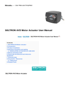
2.9 Components
1 2 3 4 5
6
7
891011
12
16
26
28
25
27
1. Cover, Inspection glass
2. Guides
3. Solenoids with block
4. Fixing ange
5. Flame tube
6. Locking, ange
7. Air intake
8. Damper motor
9. Safety valve
10. Pump
11. Nozzle control
12. Air pressure switch
13. Flame detector
14. Motor
15. Electrical box
16. Fan wheel
17. Transformer
18. Main switch
19. LMV Automatic control unit
20. Fuse
21. Overload protection
22. Contactor
23. AZL Display for LMV
Automatic control unit
24. Operating switch 0-I
25. Ignition electrodes
26. Brake plate
27. Nozzle
28. Nozzle assembly

13 Bentone
13
1415
17
20
19
18
22
21

14 Bentone
3. Electric equipment
3.1 Safety system
The safety system (safety switch for hatches, doors, water level, pressure,
temperature and other safety devices) must be installed in the safety
circuit in accordance with current regulations for the system. If these safety
requirements are met by other means, safety circuits must be bypassed.
This can differ between different systems in which the burner is installed,
see rules and regulations that apply.
The cables of the safety system must be separated so that the outgoing
signal is not placed in the same cable as the incoming signal.
3.2 Components
165 105 55-3
!Mains connection and fuse
in accordance with local
regulations.
A1 Burner control
B1 Flame detector
F1 Fuse
K1 Contactor + Overload protection
M1 Motor
S1 Operation switch
S7 Main switch
S8 Air pressure switch
S9 Pressure switch, min (Option)
T1 Ignition transformer
X1 Connection terminal board
X20 Connection terminal board
X53 Connection, Air damper
X56 Connection, Display
Y1 Solenoid valve 1
Y2 Solenoid valve 2
Y3 Solenoid valve 3
Y1S Safety valve
!
the burner.

15 Bentone
3.3 Wiring diagram
EK2
E106321
Svart
-
+
QRB
12
11
Black Schwarz Noir
A1
DC μA
Bn Brown
Bu Blue
Gn/Ye Ground/Yellow
Bk Black
Gy Grey

16 Bentone
4.1 System structure/function description
The LMV37.4... is a microprocessor-based burner management system with
matching system components for the control and supervision of forced draft
burners of medium to high capacity.
Integrated in the basic unit of the LMV37.4... are:
• Burner management system complete with valve proving system
• Electronic air-fuel ratio control system for a maximum of 2 SQM3... or
SQN1... actuators
• Control of VSD air fan
• Modbus interface
Example: Modulating burner
The system components (display and operating unit, actuators) are connected
directly to the LMV37.4... basic unit. All safety-related digital inputs and outputs
of the system are monitored by a contact feedback network.
4. LMV37 Automatic control unit
At the time of writing, of the parameters mentioned above, motor frequency
control and communication via modbus are not available on the burner models
described in this manual.
165 405 09
The LMV37 automatic control unit is a piece of control equipment that can be
used for many different types of burner.
In the following review of how this control equipment works and can be
adjusted, the description will focus on the type of burner covered by this

17 Bentone
4.2 General information
The burner management system is operated and parameterized via the
AZL2… display. The AZL2… with LCD and menu-driven operation facilitates
straightforward use and targeted diagnostics. When making diagnostics, the
display shows the operating states, the type of error and the point in time
the error occurred. Passwords protect the different parameter levels of the
burner against unauthorized access. It is possible to select from different
types of fuel trains and make use of a wide choice of individual parameter
settings (program times, conguration of inputs / outputs, etc.), enabling the
installer to make optimum adaptations to the relevant application. A change of
parameters varies in levels of authorization, this manual will give info on those
that might be changed by the installer. The actuators are driven by stepper
motors and can be positioned with high resolution. Specic features and
actuator settings are dened by the LMV37.4... basic unit.
4.3 Technical Data Basic unit LMV37.4...
Mains voltage
LMV37.400A2 AC 230 V -15 % / +10 %
Mains frequency 50 / 60 Hz ±6 %
Safety class I, with parts according to II and III to
DIN EN 60730-1
Perm. mains primary fuse
(externally)
Max. 16 AT
Unit fuse F1 (internally) 6.3 AT (DIN EN 60127 2 / 5)
Mains supply: Input current
depending on the operating state of
the unit
Under voltage
Safety shutdown from operating
position at mains voltage
LMV37.400A2 Approx. AC 186 V
Restart on rise in mains voltage
LMV37.400A2 Approx. AC 195 V

18 Bentone
M
Fuel
Air
0°
0°
t1
p
P
P
R (ON)
LP
Z
AL
V1
V2
0°
5 s5 s 30 s
POC *)
Function / Inputs
Function / Outputs
RAST plug
Pin number
RAST plug
Pin number
X3-04 Pin 1/2
X5-03 Pin 1/4
X10-05
Pin 2 / Pin 3/4
X10-06 Pin 1/2
X3-02 Pin 1/2
X5-01 Pin 2/3
X5-02 Pin 2/3
X5-02 Pin 2/3
X3-05 Pin 1
X4-02 Pin 2/3
X6-03 Pin 2/3
X8-02 Pin 1/3
X7-01 Pin 2/3
X7-02 Pin 2/3
X3-05 Pin 2
X54
X53
X74
Oil direct ignition Eo1 «Lo», «Lo mod», «Lo 2-stage», «Lo 3-stage»
Legend to the sequence diagrams

19 Bentone
!
in the individual sequence diagrams or are needed there!
Phase numbers
00 Lockout phase
02 Safety phase
10 Home run
12 Standby (stationary)
22 Fan motor (M) = ON, safety valve (SV) = ON
24 Air damper (LK) fuel valve (V) – position
30 Prepurging
36 Air damper (LK) ignition (Z) – position
38 Preignition ignition (Z) = ON
39 Test pressure switch-min (Pmin)
40 Fuel valve (V) = ON
42 Ignition (Z) = OFF
44 Interval 1 (t44)
50 Safety time 2 (TSA2)
52 Interval 2 (t52)
60 Operation 1 (stationary)
62 Operation 2 air damper (LK) low-re (KL) – position
70 Afterburn time (t13)
72 Air damper (LK) Rated load (NL) – position
74 Postpurge time (t8)
78 Postpurge time (t3)
80 Evacuation of test space
81 Atmospheric pressure test
82 Filling of test space
83 Gas pressure test
90 Gas shortage waiting time
Valve proving is performed depending on the parameter settings:
Simultaneously with the prepurge time and/or the afterburn time.

20 Bentone
Times
TSA1 1st safety time
TSA2 2nd safety time
t1 Prepurge time
t3 Postpurge time
t8 Postpurge time
t13 Afterburn time
t44 Interval 1
t52 Interval 2
Indices
1) Parameter: Short/long prepurge time for oil only
Short/long on time of oil pump – time
2) Only with valve proving during startup
3) Parameter: With/without alarm in the event of start
prevention
4) If signal is faulty in the startup phase, phase 10 is next, otherwise
phase 70
5) Max. time safety phase, then lockout
6) Time from occurrence of start prevention to signaling
7) Only in case of valve proving during startup (valve proving via
pressure switch-min)
8) Only in case of startup without valve proving (valve proving via
pressure switch -min)
9) Inverse logic in case of valve proving via pressure switch-min
10) Parameter: Oil pressure min-input
1 = active from phase 38
2 = active from safety time
11) Only with fuel train Lo and 2 fuel valves
12) Parameter 223: Repetition limit value gas pressure switch-
min in connection with gas shortage program
parameter 246 (phase 90)
13) Max. drop-in/response time for air pressure switch
14) Alternative to valve proving
15) Alternative to pressure switch-max (Pmax) or POC
/