Page is loading ...

1
002-682m-07.14
Montagehinweis
Mounting Instructions
Instruction de montage
zum Multikanalstecker
for the Multichannel Connector
pour le Connecteur Multicanal
Typ 1708B..., 1710B...
Type 1708B..., 1710B...
Type 1708B..., 1710B...

2
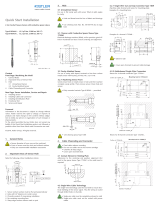
Bild 1: Kabel und Stecker Typ 1708B... separat
Bild 2: Montagehilfe
Achtung!
Alle Steckerkontakte, Gewindelöcher und Werkzeug aus-
sparungen müssen schmutz- und ölfrei sein.
Verbindung Single-Wire-Kabel mit Mehrkanalstecker
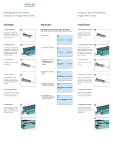
1. Single-Wire Kabel des Sensors kürzen; dabei genügend
Spiel lassen, um einen Ausbau im fertigen Werkzeug zu
vereinfachen. Kabelende nicht abisolieren (Bild 1).
2. Single-Wire-Kabel des Sensors in den offenen Schneid-
Klemmkontakt einführen und bis an den Anschlag
drücken.
3. Die Montagehilfe (Bild 2) über die Klemmstecker schie-
ben und von Hand im Uhrzeigersinn festdrehen; das
Kabel wird hierbei automatisch abisoliert und geklemmt
(Bild 3). Anschliessend kann die Montagehilfe wieder
entfernt werden.
Bild 3: Single-Wire-Kabel montiert

3
deutsch
Verbindung Mehrkanalstecker mit Werkzeug
1. Den Mehrkanalstecker mit zwei Schrauben im Werkzeug
befestigen; dabei wird der Deckel des Fischer-Steckers
mit einer Schraube fixiert. Beim Einbau von zwei
Mehrkanalsteckern kann das rote Markierungsschild
(Art.-Nr. 3.520.103) zur farblichen Kennzeichnung ver-
wendet werden (Bild 4+5).
2. Das Beschriftungsschild mit Angaben der Systemnummer,
Serien nummer und Sensorempfindlichkeit am Werkzeug
befestigen (Bild 5).
Bild 4: Stecker Typ 1708B... im Werkzeug
Bild 5: Steckereinbau Typ 1708B... mit Beschriftungsschild
Prüfen der eingebauten Sensoren
Die Empfindlichkeit und Isolation der einzelnen Sensoren
werden mit dem Prüfgerät Typ 5495B... verifiziert. Dazu
werden folgende Kabel benötigt:
Typ 1999A1A0,5 für 4-Kanalstecker Typ 1708B...
Typ 1999A2A0,5 für 8-Kanalstecker Typ 1710B...

4
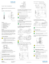
Connecting Single-Wire Cable with Multi-Channel Connector
1. Cut the single-wire cable to length, allowing enough
free length for service in the assembled mold. Do not
strip the insulation (Fig. 1).
2. Feed the cable into the open cut-and-grip contact and
push it fully in.
3. Slip the mounting aid (Fig. 2) over the clamping contact
and tighten it clockwise by hand. This automatically strips
and clamps the cable (Fig. 3). Afterwards you can remove
the mounting aid.
Fig. 1: Cable and connector Type 1708B... separate
Fig. 2: Mounting aid
Caution!
Ensure that all connector contacts, threaded holes and
tool recesses are free of dirt and oil.
Fig. 3: Cable installed

5
english
Installing Multi-Channel Connector into Mold
1. Secure the multi-channel connector in the mold with
two screws, while at the same time securing the Fischer
connector cap with one screw. When installing two
multi-channel connectors the red marker plate (Art.No.
3.520.103) may be used to color-code one connector
(Fig. 4+5).
2. Secure the identification plate with details of the system
number, serial number and sensor sensitivity to the mold
(Fig. 5).
Fig. 4: Connector Type 1708B... in the mold
Fig. 5: Connector mounting Type 1708B... with identification plate
Testing the Installed Sensors
The sensitivity and insulation of each sensor is verified with
the tester Type 5495B... .
The cables required are as follows:
Type 1999A1A0,5 for 4-channel Connector Type 1708B...
Type 1999A2A0,5 for 8-channel Connector Type 1710B...

6
Fig. 1 : câble et prise de type 1708B... séparés
Fig. 2 : câble monté
Attention!
Il faut s‘assurer que les connecteurs ainsi que le loge ment
des capteurs soient exempts de toute pollution.
Liaison entre câble monofilaire et prise multicanaux
1. Raccourcir le câble monofilaire et laisser suffisamment de
jeu pour simplifier le démontage dans le moule. Ne pas
dénuder le câble (Fig. 1).
2.
Introduire le câble monofilaire du capteur dans la borne à
couper-connecter et l‘enfoncer jusqu‘à la butée.
3. Monter l'outil de montage (Fig. 2) sur le prise de pincer
dans le sens des aiguilles d'une montre. Le câble est
automatiquement dénudé et connecté (Fig. 3). Ensuite
on peut détacher l'outil de montage.
Fig. 3 : câble monté

7
français
Liaison entre prise multicanal et moule
1. Fixer la prise multicanal dans le moule à l’aide de deux
vis vis, le bouchon de la prise Fischer se fixe avec une
vis. Lors du montage de deux prises multicanal, la pla-
que signalétique rouge (réf. 3.520.103) peut servir à
identifier les prises par des couleurs (Fig. 4+5).
2. Fixer la plaque signalétique au moule en indiquant le
numéro du système, le numéro de série et la sensibilité
du capteur (Fig. 5).
Fig. 4 : Prise de type 1708B... dans le moule
Fig. 5 : Montage de prise de type 1708B... avec plaque signalétique
Contrôle des capteurs montés
La sensibilité et l’isolation des différents capteurs doivent
être vérifiées au moyen du contrôleur de type 5495B... .
Pour cela, utiliser les câbles suivants :
Type 1999A1A0,5 pour prise 4 canaux de type 1708B...
Type 1999A2A0,5 pour prise 8 canaux de type 1710B...

8
www.kistler.com
002-682m-07.14 ©2014, Kistler Gruppe
/

