Ransomes 544913 Owner's manual
- Category
- Mini tillers
- Type
- Owner's manual

GB
Safety & Operation
Manual
GA 60
Model 544913
4117232-Rev A

Litho in U.S.A. 10-2002
2002 TEXTRON INC. • All Rights Reserved.
Lincoln, Nebraska • Printed in U.S.A.
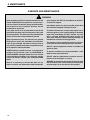
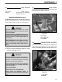
GENERAL INFORMATION
IMPORTANT!
THIS MANUAL WILL AID YOU IN THE SAFE
OPERATION AND PROPER MAINTENANCE OF
YOUR EQUIPMENT. READ MANUAL THOROUGHLY
BEFORE ATTEMPTING OPERATION. IF ANY
PORTION IS NOT CLEARLY UNDERSTOOD,
CONTACT AN AUTHORIZED DEALER FOR
CLARIFICATION.
To make sure you are fully aware of safety and service
information, the following two symbols are used
throughout this manual.
!!
This symbol is used throughout the manual to
alert you to information about unsafe actions or
situations, and will be followed by the word DANGER,
WARNING, or CAUTION. DANGER indicates
immediate hazards that may result in severe injury or
death. WARNING indicates unsafe actions or situations
that may cause severe injury, death and/or major
equipment or property damage. CAUTION indicates
unsafe actions or situations that may cause injury, and/or
minor equipment or property damage.
NOTE: This appears next to information or instructions
which will help you operate and maintain your
equipment the right way.
WARNING
!
S The information and instructions included
in this manual alert you to certain things
you should do very carefully. If you do not,
you could:
• hurt yourself or others
• hurt the next person who operates the
equipment
• damage the equipment.
S This manual contains essential operation
and safety information and must remain
with the unit at all times, within easy ac-
cess of any operator.
Additional manuals are available through your dealer.
IMPORTANT!
THIS EQUIPMENT SHOULD NOT BE MODIFIED OR
ADDED TO WITHOUT THE MANUFACTURER’S
AUTHORIZATION.
WARNING
!
S Altering this equipment in any manner
which adversely affects the equipments
operation, performance, durability or use,
may cause hazardous conditions.
Direct any inquiries to:
Textron Golf, Turf and Specialty Products
Attn: Director of Engineering
P.O. Box 7708
Charlotte, NC 28241–7708 USA
SPECIFICATION INFORMATION
All information contained in this manual is the latest
available at the time of printing. Textron Golf, Turf and
Specialty Products reserves the right to make changes
at any time without notice.
Whenever a name brand product is specified, an
equivalent product may be used unless stated otherwise.
CHANGE OF OWNERSHIP OR ADDRESS
Textron Golf, Turf and Specialty Products makes every
effort to keep owners informed of all safety related
information. Therefore, changes in ownership and/or
address should be reported to the manufacturer.
Your dealer has REGISTRATION CHANGE FORMS
which will be filled out and filed by the dealer for his
records, and a copy will be sent to the manufacturer.
DEALER INFORMATION
For your nearest dealer location write to:
Textron Golf, Turf and Specialty Products
Attn: Sales
P.O. Box 7708
Charlotte, NC 28241–7708 USA
In the USA and Canada call 1–800–228–4444 (dealer
information only).

1
TABLE OF CONTENTS
1 Operation Safety 2. . . . . . . . . . . . . . . . . . . . . . . . . . . . . . . . . . . . . . . . . . . .
2 Decals 3-4
. . . . . . . . . . . . . . . . . . . . . . . . . . . . . . . . . . . . . . . . . . . . . . . . . . .
3 Identification 5
. . . . . . . . . . . . . . . . . . . . . . . . . . . . . . . . . . . . . . . . . . . . . . .
3.1 Model Number and Serial Number 5. . . . . . . . . . . . . . . . . . . . . . . . . . . . . . .
4 Service Parts and Support Material 5. . . . . . . . . . . . . . . . . . . . . . . . . .
5 Specifications 6
. . . . . . . . . . . . . . . . . . . . . . . . . . . . . . . . . . . . . . . . . . . . . .
5.2 Towing Vehicle Specifications (Turf Trucksters) 6. . . . . . . . . . . . . . . . . . . .
5.3 Towing Vehicle Specifications (Turf Utility Tractor) 6. . . . . . . . . . . . . . . . .
6 Set Up 7. . . . . . . . . . . . . . . . . . . . . . . . . . . . . . . . . . . . . . . . . . . . . . . . . . . . .
6.1 Set Up Instruction for Turf Truckster 7. . . . . . . . . . . . . . . . . . . . . . . . . . . . .
6.2 Power Cable Installation 7. . . . . . . . . . . . . . . . . . . . . . . . . . . . . . . . . . . . . . .
6.3 Tongue Installation 8. . . . . . . . . . . . . . . . . . . . . . . . . . . . . . . . . . . . . . . . . . . .
6.4 Hitch Coupler Installation 9. . . . . . . . . . . . . . . . . . . . . . . . . . . . . . . . . . . . . . .
6.5 Reinstalling Side Panels 9. . . . . . . . . . . . . . . . . . . . . . . . . . . . . . . . . . . . . . . .
6.6 Set Up Instruction for Tractor 10. . . . . . . . . . . . . . . . . . . . . . . . . . . . . . . . . .
6.7 Removing From Pallet 11. . . . . . . . . . . . . . . . . . . . . . . . . . . . . . . . . . . . . . . .
6.8 Installing Tines 12. . . . . . . . . . . . . . . . . . . . . . . . . . . . . . . . . . . . . . . . . . . . . . .
7 Operation 13. . . . . . . . . . . . . . . . . . . . . . . . . . . . . . . . . . . . . . . . . . . . . . . . .
7.1 Pre–Operation Check 13. . . . . . . . . . . . . . . . . . . . . . . . . . . . . . . . . . . . . . . . .
7.2 Control Panel 13. . . . . . . . . . . . . . . . . . . . . . . . . . . . . . . . . . . . . . . . . . . . . . . .
7.3 Before Starting Engine 13. . . . . . . . . . . . . . . . . . . . . . . . . . . . . . . . . . . . . . . .
7.4 GA–60 Starting Procedure 14. . . . . . . . . . . . . . . . . . . . . . . . . . . . . . . . . . . . .
7.5 Beginning Aeration 14. . . . . . . . . . . . . . . . . . . . . . . . . . . . . . . . . . . . . . . . . . .
7.6 Aerating Depth Adjustment 15. . . . . . . . . . . . . . . . . . . . . . . . . . . . . . . . . . . .
8 Maintenance 13. . . . . . . . . . . . . . . . . . . . . . . . . . . . . . . . . . . . . . . . . . . . . . .
8.1 Daily Maintenance 17. . . . . . . . . . . . . . . . . . . . . . . . . . . . . . . . . . . . . . . . . . . .
8.2 Lubrication Fittings 17. . . . . . . . . . . . . . . . . . . . . . . . . . . . . . . . . . . . . . . . . . .
8.3 Air Cleaner 18. . . . . . . . . . . . . . . . . . . . . . . . . . . . . . . . . . . . . . . . . . . . . . . . . .
8.4 Checking Element 18. . . . . . . . . . . . . . . . . . . . . . . . . . . . . . . . . . . . . . . . . . . .
8.5 Installing Element 18. . . . . . . . . . . . . . . . . . . . . . . . . . . . . . . . . . . . . . . . . . . .
8.6 Fuel System 19. . . . . . . . . . . . . . . . . . . . . . . . . . . . . . . . . . . . . . . . . . . . . . . . .
8.7 Fuel Filter 19. . . . . . . . . . . . . . . . . . . . . . . . . . . . . . . . . . . . . . . . . . . . . . . . . . .
8.8 Engine Choke Control 19. . . . . . . . . . . . . . . . . . . . . . . . . . . . . . . . . . . . . . . .
8.9 Engine Oil 20. . . . . . . . . . . . . . . . . . . . . . . . . . . . . . . . . . . . . . . . . . . . . . . . . . .
8.10 Engine Oil Level 20. . . . . . . . . . . . . . . . . . . . . . . . . . . . . . . . . . . . . . . . . . . . .
8.11 Drive Chain Lubrication 20. . . . . . . . . . . . . . . . . . . . . . . . . . . . . . . . . . . . . . .
8.12 Towing 20. . . . . . . . . . . . . . . . . . . . . . . . . . . . . . . . . . . . . . . . . . . . . . . . . . . . . .
8.13 Tire Pressure 20. . . . . . . . . . . . . . . . . . . . . . . . . . . . . . . . . . . . . . . . . . . . . . . .
8.14 Daily Storage 20. . . . . . . . . . . . . . . . . . . . . . . . . . . . . . . . . . . . . . . . . . . . . . . .
9 Tine Holders 21. . . . . . . . . . . . . . . . . . . . . . . . . . . . . . . . . . . . . . . . . . . . . . .
10 Tines 22-23. . . . . . . . . . . . . . . . . . . . . . . . . . . . . . . . . . . . . . . . . . . . . . . . . . .
11 Torque Chart 24
. . . . . . . . . . . . . . . . . . . . . . . . . . . . . . . . . . . . . . . . . . . . . .
12 Warranty 25–26
. . . . . . . . . . . . . . . . . . . . . . . . . . . . . . . . . . . . . . . . . . . . . . .

1 OPERATION SAFETY
2
WARNING
!
EQUIPMENT OPERATED IMPROPERLY OR BY
UNTRAINED PERSONNEL CAN BE DANGEROUS
This is heavy equipment. Improper use, or operat-
ing the unit in areas that may cause it to overturn,
could cause serious injury or death to you the oper-
ator or bystanders.
READ and understand the operator’s manual be-
fore attempting to operate this unit.
Immediately replace any warning and/or safety
decal that becomes damaged or difficult to read.
This product is heavy equipment and may present a
crush hazard unless safety precautions are taken.
DO NOT place hands or feet beneath unit at any
time, unless engine is shut off and yellow uplatch
bar is securing unit in “UP” position.
Allow ONLY trained and authorized persons to op-
erate this unit. NEVER allow children to operate this
unit. Local regulations may restrict the age of the
operator.
Use ONLY the standard drawbar approved by the
tractor manufacturer. The height from the ground
to the top of the drawbar must be 13 to 19.7 inches
(330–500 mm).
Never operate the unit while under the influence of
alcohol or drugs.
Never operate the unit while people, especially chil-
dren, or pets are nearby.
Keep in mind that the operator or user is responsi-
ble for accidents or hazards occurring to other
people or property.
BEFORE using the unit, always inspect it for prob-
lems. If something is wrong, DO NOT USE IT. Fix the
problem before using the unit to prevent possible
injury.
WHILE using the unit, if something is found to be
wrong, STOP using it. Fix the problem before the
unit is used again.
Operate the machine up and down the slope (verti-
cally), not across the face of the slope (horizon-
tally).
ALWAYS use good judgement when operating on
or near hills or slopes. NEVER start or stop sud-
denly, you may cause unstable operating condi-
tions. NEVER change directions abruptly or make
sharp turns on slopes.
DO NOT place hands or feet near or under moving
parts at any time.
Check work area and remove foreign objects which
may be a hazard to the operator, bystanders or
damage the equipment.
To prevent damage to the unit or other equipment,
BE SURE all under ground obstacles are clearly
marked.
Make sure all shields and guards are in place to
prevent possible injury.
NEVER attempt to aerate in reverse.
Always run unit engine where there is plenty of
fresh air to prevent a buildup of carbon monoxide
fumes. Carbon monoxide is colorless, odorless
and deadly. NEVER run unit in an enclosed space
where exhaust fumes will collect.
Never use the unit in, or near an area where there is
dust or fumes in the air which may be explosive.
The electrical and exhaust systems of this unit will
make sparks which could ignite explosive materi-
als.
DO NOT operate unit over any hard surfaces (drive-
ways, sidewalks, etc.) with aerator heads in low-
ered position.
Always stop engine and DO NOT smoke or allow
open flames or sparks when refueling. Gasoline is
extremely flammable and highly explosive under
certain conditions.
DO NOT remove radiator cap while engine is hot.
Radiator contents are under pressure and spray
may cause serious injury. Read this manual thor-
oughly to be aware of safe operating procedures.
Gasoline is extremely flammable and highly explo-
sive under certain conditions.
Never remove the fuel tank cap or attempt to refuel
the GA–60 or Turf–Truckster while either engine is
operating.

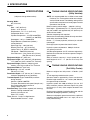
DECALS 2
3
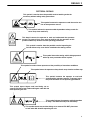
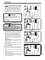
PICTORIAL DECALS
This decal instructs the operator to read and understand the operators
manual. To prevent injury, they must be familiar with the operation of this
product and be fully aware of all safe operating procedures.
This symbol shows fingers and hand being cut or
severed. DO NOT place hands and fingers under GA–60
while operating the unit.
This symbol shows toes and feet being cut or severed. DO NOT place toes
or feet under GA–60 while operating the unit.
This symbol instructs the operator to read and
understand the operators manual. To prevent injury,
they must be aware of safe operating procedures.
This symbol is used to show the possible result of operating the
GA–60 without a tip– over device attached to the towing vehicle.
This symbol shows the towing vehicle being operated
with a tip–over prevention device in place.
This symbol informs the operator and/or bystanders
to keep a safe distance away from machinery.
This symbol is used to inform operators of the possiblity of hazardous conditions.
This symbol warns the operator to keep hands away from hot radiator cap.
This symbol instructs the operator to read the service sec-
tion of the operators manual.
This symbol informs the operator and/or bystanders to keep a safe dis-
tance away from machinery.
This symbol is used to show the possible result of working under the
machinery without taking safety precautions.

2 DECALS
4
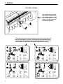
PICTORIAL DECALS
This symbol shows the posi-
tion of the up latch bar pin
when the heads are in the up
and locked position. Also
shown is the pin position for
the unlocked position.
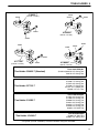
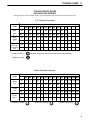
These operation decals show the auxiliary transmission in low range and
the drive transmission in low gear. Use the decal that corresponds with the
Turf Truck you are operating (refer to page 15 of this manual). The various
engine speeds are also shown with the corresponding hole spacing.
845441
2100
2400
2700
3000
MM.
90
100
115
125
(INCH)
(3 1/2)
(4)
(4 1/2)
(5)
N/MIN
660CC
845442
2800
3200
3600
4000
MM.
90
100
115
125
(INCH)
(3 1/2)
(4)
(4 1/2)
(5)
N/MIN
1600
1800
2100
2300
MM.
90
100
115
125
(INCH)
(3 1/2)
(4)
(4 1/2)
(5)
N/MIN
840892
845440
3000
3500
4000
4400
MM.
90
100
115
125
(INCH)
(3 1/2)
(4)
(4 1/2)
(5)
N/MIN
660CC

IDENTIFICATION 3
5
3 IDENTIFICATION
THESE IDENTIFICATION NUMBERS MUST APPEAR
ON ALL CORRESPONDENCE CONCERNING THIS
UNIT.
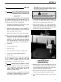
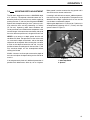
3.1 MODEL NUMBER & SERIAL NUMBER
Both the Model Number and Serial Number are on the
identification nameplate located on the right side of the
tool box by the gas tank (See Fig. 1).
1
Figure 1
1. Identification Nameplate
4 SERVICE PARTS AND
SUPPORT MATERIAL
Description Part Number. . . . . . . . . . . . . . . . . . . . . . . .
Drive Belt 835063. . . . . . . . . . . . . . . . . . . . . . . . . . . . . . . .
Chain, #50 sealed roller, 69 links 891956. . . . . . . . . . . .
Connector, #50 sealed 522123. . . . . . . . . . . . . . . . . . . . .
Element, Fuel Filter 821814. . . . . . . . . . . . . . . . . . . . . . . .
Element, Air Filter 840352. . . . . . . . . . . . . . . . . . . . . . . . .
Element, Oil Filter 833438. . . . . . . . . . . . . . . . . . . . . . . . .
Condenser, Ignition 833475. . . . . . . . . . . . . . . . . . . . . . . .
Spark Plug 835825. . . . . . . . . . . . . . . . . . . . . . . . . . . . . . .
Points, Ignition 888587. . . . . . . . . . . . . . . . . . . . . . . . . . . .
Rotor, Ignition 888588. . . . . . . . . . . . . . . . . . . . . . . . . . . . .
Chain Lubricant, Spray 523248. . . . . . . . . . . . . . . . . . . . .
Wool Grease 893078. . . . . . . . . . . . . . . . . . . . . . . . . . . . .
Parts and Maintenance Manual 4117233. . . . . . . . . . . .
Coring tines See page 22. . . . . . . . . . . . . . . . . . . . . . . . .
Touch up paint, Jacobsen Orange
16 oz. (.5L) spray 2700345. . . . . . . . . . . . . . . . . . . . . . .
1 qt. (.95L) can 2700351. . . . . . . . . . . . . . . . . . . . . . . . . .
Black, 16 oz. (.5L) spray 814294. . . . . . . . . . . . . . . . . . .

5 SPECIFICATIONS
6
5 SPECIFICATIONS
(subject to change without notice)
Aerating Width:
60” (1524 mm)
Engine:
Bore – 2.62” (66.5 mm)
Stroke – 3.19” (81 mm)
Displacement – 51.7 cu. in. (847 cm3)
Compression Ratio – 9.5:1
Cylinder Compression – 213 PSI at 400 RPM
(1486 KPa at 400 RPM)
Horsepower – 33 h.p. at 3600 RPM
Engine Rotation (viewed from flywheel) –
counterclockwise
Spark Plug Gap – .032 (0.81 mm)
Breaker Point Gap – .017 (0.43 mm)
Ignition Timing – 0° BTDC at 1000 RPM
Idle Speed – 1300 RPM (minimum)
Valve Clearance – (Hot) Intake .010 (.25 mm)
(Hot) Exhaust .012 (.30 mm)
Equipment Height: 42” (1067 mm)
Equipment Length: 101” (2565 mm) (GA 60 alone)
172” (4369 mm) (with 3–wheel Turf–Truckster)
Equipment Weight: 2209 lbs. (1002.8 kg) with
440 lbs. (199.7 kg) carried on Turf–Truckster
Equipment Width: 92” (2337 mm)
Hole Spacing: 3 1/2” to 5” variable
(89 mm to 127 mm)
Penetration Depth: 2 1/2” (64 mm) to 4” (102 mm)
maximum (depending on soil conditions)
Truckster Speed: Engine: 2300 RPM (maximum
during aeration)
Aeration: 1500 to 2300RPM
Transport: Reasonable safe speed (10 mph max.)
Use caution when towing aerator at
speeds above 5 M.P.H.
Standard Tines: Type: Hollow, tapered (self–cleaning)
Material: Through hardened steel
Quantity: 24 tines per unit
Sizes: 3/4” (19 mm)
Tires: Size: 23 – 10.50 x 12 High flotation
Recommended Pressure – 18 psi
5.2 TOWING VEHICLE SPECIFICATIONS
(Utility Vehicles)
NOTE: It is recommended that an 8720 or later model
Cushman Turf–Truckster be used to tow and oper-
ate the GA–60 aerator. The following towing vehicle
specifications must be met to insure proper and safe
operation of the GA–60.
Minimum towing vehicle weight – 1000 lbs. (454 kg)
Hitch height – approximately 31 1/4” (794 mm) for 9120
and prior models and approximately 25” (635 mm) for
9210 and later models.
Vibration dampening hitch required.
Mechanism to insure towing vehicle will not tip over back-
wards when attached to GA–60.
Brakes – 7” (178 mm) hydraulic (minimum) on axle with
most weight.
Brake light system to power the electric brakes.
Hydraulic system requirements: 1800 psi minimum
at 5 gallons per minute.
Variable speed governor (22 H.P. minimum engine size).
Mechanical transmission and drive to prevent change in
ground speed.
Ability to maintain constant 1–2 mph speed with gov-
erned engine for 3 1/2” – 5” (89 mm to 127 mm) core
spacing.
5.3 TOWING VEHICLE SPECIFICATIONS
(Turf Utility Tractor)
Minimum weight of turf utility tractor – 2700 lbs. (1225
kg).
12 volt negative ground electrical system.
Standard drawbar approved by tractor manufacturer.
Drawbar height must be 13 – 19.7 inches (330–500 mm)
from ground to top of drawbar.
Hydraulic system with 1800 to 2250 psi (12.4 to 15.5
MPa) maximum pressure. Minimum output of 3 gallon
per minute (11.4 L/min). Quick couplers located at rear
of tractor.
Braking system capable of controlling the tractor and the
towed GA–60 weighing 2300 lbs. (1044 Kg).
Governor and properly geared transmission capable of
controlling ground speed from 1 to 2 mph (1.6 to 3.2
km/hr) while aerating.

SET UP 6
7
6 SET UP
6.1 SET–UP INSTRUCTIONS FOR
CUSHMAN TURF–TRUCKSTER
IMPORTANT!
TO UTILIZE YOUR CUSHMAN TURF–TRUCKSTER
AS A TOWING VEHICLE FOR THE GA–60, THE FOL-
LOWING KITS/ACCESSORIES SHOULD FIRST BE
INSTALLED ON THE TURF–TRUCKSTER:
1. Quick disconnect power cable installation kit (parts
included in the GA–60 loose parts bag).
2. Hydraulic remote coupler kit (Part No. 889558) for
9020 Turf–Truckster models and prior or hydraulic
system for models 9110 and later.
3. Fifth wheel and electric brake control installation kit.
NOTE: To utilize 5th wheel implements not equipped
with tongue extensions on 8710–9120 model Turf
Trucksters, use 5th wheel hitch kit (Part No.
889623). To use 5th wheel implements equipped
with a tongue extension on 8710 & later Turf Truck-
sters, use 5th wheel hitch kit (Part No. 890170).
4. Tachometer.
5. Variable speed governor.
6. Hydraulic system.
7. 3.2:1 ratio auxiliary transmission (9120 & prior).
8. 11.16:1 ratio 2–speed standard differential
(9210 & later).
During transport with the aerator heads raised, the GA 60
can be transported at any reasonable safe speed
(10mph maximum) ALWAYS use extreme care when
towing aerator at any speeds above 5 mph.
6.2 POWER CABLE INSTALLATION
NOTE: These instructions are for persons using Cush-
man Turf–Truckster (8720 and later) models
898530, 898532, 898630, 898632, 898633 and
898634 to tow their GA–60.
If using towing vehicle other than the Turf Trucksters
listed above, use good judgment in finding a suit-
able mounting location for the power cable.
BE SURE there is adequate cable length to connect
to the GA–60 and for turning either direction without
disconnecting the power cable.
WARNING
!
To prevent sparks, disconnect the negative (–)
battery cable before installing power cable.
1. Locate the right side backrest support bracket on the
seat back. Just below the bracket on the support
panel flange is an existing 5/16” (8 mm) hole.
2. With (1) one 1/4–20 x 1 1/4” screw, nut and lock-
washer from the loose parts bag, loosely attach
power cable connector to support panel flange using
existing 5/16” (8 mm) hole. See figure 2.
1
2
3
4238
Figure 2
1. Power Cable Assembly
2. Mounting Hardware
3. Support Panel Flange
3. Before drilling a second mounting hole, mark the
hole location by placing a pointed object (punch, awl,
etc.) through the second hole in the power cable con-
nector and lightly scratching the surface.
4. Rotate power cable connector away from the second
hole location to allow easier access for drilling.
5. Drill second mounting hole using a 1/4” (6.5 mm) drill
bit.

6 SET UP
8
6. Rotate cable connector back to original position and
secure with (1) one 1/4–20 x 1 1/4” screw, lock-
washer and nut from the loose parts bag. Tighten all
hardware.
7. Connect eyelet end of black cable to vehicle frame
negative ground location using existing hardware.
8. Using the existing hardware on the starter solenoid
(located on the stopwall), connect the red cable end
from power cable connector to the solenoid post the
positive cable from the battery is connected to.
9. Reconnect the negative (–) battery cable to the bat-
tery.
6.3 TONGUE INSTALLATION
WARNING
!
To prevent possible injury to yourself or oth-
ers, stay clear when cutting banding. Banding
is under tension and may snap back when cut.
Wearing leather gloves or similar protection
will help protect hands from sharp edges when
removing banding from shipping pallet.
DO NOT operate equipment until you have
thoroughly read and completely understand
the controls and operation sections of this
manual. If anything is not completely under-
stood, contact your CUSHMAN dealer for clari-
fication before operating equipment.
1. Loosen and raise left (facing front of unit) top cover
and latch in the UP (raised) position.
2. Open air duct lid and remove loose parts bag from
tool box.
3. Carefully cut and remove all banding securing the
GA–60 tongue components to the shipping pallet.
4. Turn jack handle counterclockwise to raise jack. Pull
locking pin from jack and swivel jack towards rear of
unit. Using the locking pin, lock the jack in the UP
(raised) position.
CAUTION
!
The tongue components are very heavy. To
avoid injury, BE SURE to have assistance
when lifting or moving any of these compo-
nents.
5. Carefully slide tongue components out from under
sides of GA–60 and remove from pallet.
6. Loosen the right side top cover panel and raise till
latched in the UP (raised) position.
CAUTION
!
Use caution when removing upper side panel
mounting screws. When screws are removed
from panel, the panel inner support assembly
will become loose and could fall.
7. Remove both upper side panels, both lower panels,
upper support assemblies and lower support brack-
ets. Retain mounting screws.
8. Loosen and remove all hardware including isolation
mounts from (2) two unpainted shipping plates
located at the tongue mounting locations. Refer to
Figure 3. Retain all original hardware except nuts.
1
2
3
4244
Figure 3
1. Shipping Plate
2. Isolation Mounts
3. Upper Support Assembly
9. Discard shipping plates and the four (4) nuts
removed with each plate.

SET UP 6
9
10. With three (3) 5/8–11 x 4” hitch bolts, attach right side
tongue tube to main frame assembly. See Figure 4.
Attach left side tongue tube to frame. Do not secure
at this time.
1
2
5083
Figure 4
1. Tongue Tube
2. Mounting Hardware
11. Using four (4) 5/8–11 x 5” screws, lockwashers, nuts
and eight (8) thrust washers, attach short or long
tongue extension to right and left tongue tubes. See
Figures 5 and 6.
1
5084
Figure 5
1. Short Tongue Extension
(used when towed w/turf–truckster)
1
2
5085
Figure 6
1. Long Tongue Extension
(used when towed w/tractor)
2. Hose Support
12. Torque the six (6) 5/8–11 x 4” hitch bolts to 120 ft.–
lbs. (162 to 163 N⋅m). Torque the four (4) 5/8–11 x 5”
screws to 120 ft.–lbs. (162 to 163 N⋅m).
NOTE: When using the long tongue extension, attach
the hose support to the tongue extension as shown
in Figure 6.
13. Cut tie strap and uncoil hydraulic hoses, power
cable, and control panel cable and route them down
the right (facing the front of unit) side of tongue,
securing them with tie straps. The hoses should then
be routed through the hose support on the fifth wheel
of the towing vehicle.
6.4 HITCH COUPLER INSTALLATION
1. Raise the tool box lid and remove the hitch coupler.
Attach the hitch coupler to the tongue extension
using two (2) 1/2–13 x 4 1/4” screws, nuts and lock-
washers.
2. Torque the two (2) screws to 75 ft.–lbs. (102 N⋅m).
6.5 REINSTALLING SIDE PANELS
1. Reinstall both upper side panels using all original
hardware except for nuts. Replace shipping nuts
with new centerlock nuts from loose parts bag.
NOTE: For easier installation of the lower side cover
panel, attach the panel bracket to the inside of the
panel using double sided tape or a similar material.
2. Using original retained hardware, reinstall both lower
side cover panels.
3. Unlatch and lower both top cover panels and secure
in the DOWN (lowered) position.

6 SET UP
10
6.6 SET–UP INSTRUCTIONS FOR
TURF UTILITY TRACTOR
1. Install and secure a 2” (51 mm) tow hitch ball to the
standard tractor drawbar. BE SURE the hitch ball is
a class 2 (3500 lb. capacity) or better ball.
CAUTION
!
Use ONLY the standard drawbar approved by
the tractor manufacturer. The height from the
ground to the top of the drawbar must be 13 to
19.7 inches (330–500 mm).
2. Mount power cable assembly (Part No. 889171) in a
suitable location at the rear of the tractor. Connect
the red cable end to the same post the tractor posi-
tive battery cable is attached to. Connect the black
cable to a good ground on the tractor frame. Refer to
wiring diagram.
NOTE: Cable lengths and eyelets may need to be modi-
fied depending upon the configuration of your trac-
tor.
3. Mount the GA–60 control panel at a location within
arms reach of the tractor operator. Connect the con-
trol box harness (Part No. 889174) to the GA–60
main harness (Part No. 889547). A wire harness
extension (Part No. 892790) may be used if addi-
tional wire harness length is required. This extension
is included in the long extension accessory (Part No.
892964).
4. The wheel brakes on the GA–60 are NOT USED
when towed with a turf utility type tractor. The brake
bypass jumper (Part No. 892793) must be plugged
into the wire assembly (Part No. 889052) on the
GA–60 control panel. See Figure 7. If the brake
bypass jumper is not installed, the GA–60 engine will
not start. Refer to wiring diagram.
1
2
5082
Figure 7
1. Brake Bypass
2. Control Panel
NOTE: The GA–60 brakes are not utilized therefore the
towing tractor must weigh a minimum 2700 lbs.
(1225 Kg). The tractor brakes must be capable of
controlling the tractor and the 2300 lb. (1044 Kg)
GA–60.
5. Determine what type and size hydraulic quick cou-
plers are used on the towing tractor. Change the
ends on the GA–60 hydraulic hoses to match the
towing tractor hydraulic fittings. Add to hydraulic
hose length if required.
6. Attach long tongue extension to 2” (51 mm) hitch
ball on tractor draw bar. Route the wire harness,
power cable and hydraulic hoses through the hose
support mounted on the long tongue extension.
7. Connect wire harness, power cable and hydraulic
hoses to tractor. Remove GA–60 from pallet as
described in the following section.
8. With the GA–60 engine turned off and the heads in
the “UP” position, pull and turn the tractor fully to the
left and right. Make sure all hoses, wiring and hitch
move freely and are not rubbing against adjacent
parts.
9. With the GA–60 heads in the “UP” position, disen-
gage the uplatch bar shown in Figure 8. Start the
GA–60, move to a turf area and lower the aerator
heads. Lowering the aerator heads will increase the
GA–60 engine speed and will engage the aerator

SET UP 6
11
drive as it lowers. The aerator drive will disengage
and engine will return to idle when the aerator heads
are raised.
NOTE: If raising the hydraulic lever lowers the aerator,
the hydraulic lines are reversed. Reverse the
hydraulic lines at the quick couplers.
10. The GA–60 can produce a maximum hole spacing of
5” (125 mm). Hole spacings larger than 5” (125 mm)
will SEVERELY DAMAGE the aerator mechanism.
NOTE: The tractor speed MUST BE kept below 2 mph
(3.2 km/hr) when aerating. BE SURE to use an
engine speed and transmission gear that will result
in a hole spacing of less than 5” (127 mm). Aerating
speeds exceeding the allowable 2 mph (3.2 km/hr)
will SEVERELY DAMAGE the aerator mechanism
components.
Hole
Spacing
Miles
Per
Hour
2.5”
3.7”
5.0”2.0
1.5
1.068 seconds
51 seconds
34 seconds
Approximate
time needed to
drive 100’
Tractor Hole Spacing Chart
Inches
(30.5 Meters) (Km/hr.) (mm)
During transport with the aerator heads raised, the GA 60
can be transported at any reasonable safe speed
(10mph maximum) ALWAYS use extreme care when
towing aerator at any speeds above 5 mph.
NOTE: The GA 60 may be damaged if towed on a
flatbed trailer without the aerator heads lowered.
Place boards or similar type material on the trailer to
prevent damage to trailer and/or tines when the
heads are lowered.
6.7 REMOVING FROM PALLET
1. Carefully cut and remove all banding securing aera-
tor to shipping pallet.
2. Back the towing vehicle up to the GA–60. Position
the towing vehicle so the tongue may be lowered
onto the 5th wheel ball.
3. Loosen mounting clamp knob on rear of control
panel to allow the control panel to be mounted on the
right side hand hold of the Turf–Truckster or towing
vehicle. Tighten mounting clamp knob to secure.
4. Connect control panel cable from GA–60 to right side
of control panel. Attach multi–pin connector from the
bottom of the control panel to the connector
mounted on the right stopwall support.
5. Lock the hydraulic lift control on the Turf–Truckster
or towing vehicle in the float position to relieve
hydraulic pressure. This will allow the hydraulic
hoses to be connected more easily.
NOTE: After connecting the hydraulic hoses, BE SURE
to release the hydraulic lift control from the float
position.
6. Connect the quick coupler power cable from the
GA–60 to the Turf–Truckster or towing vehicle.
7. Start the Turf–Truckster or towing vehicle engine and
raise the aerator heads slowly to lower the tongue
onto the fifth wheel ball. Tighten ball grip to fifth wheel
ball by turning square nut on hitch coupler clockwise
until tight.
8. Raise aerator heads as high as possible to allow
GA–60 to be removed from pallet.
NOTE: Place various thickness boards or blocks in front
of pallet to help prevent the GA–60 from dropping to
the ground from pallet during removal.
BE SURE aerator heads are raised to their maxi-
mum height to assure the turf guards do not catch
on pallet.
WARNING
!
DO NOT allow anyone to stand directly behind
pallet during removal of the GA–60.
The weight of the unit may cause the pallet to
slide back quickly when the GA–60 is removed.
9. Slowly drive the Turf–Truckster or towing vehicle for-
ward to remove GA–60 from pallet.

6 SET UP
12
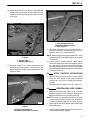
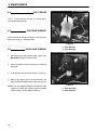
6.8 INSTALLING TINES
WARNING
!
DO NOT attempt to install tines with either the
aerator or towing vehicle engine running.
Remove key from towing vehicle and discon-
nect power cable to GA 60 to insure that neither
engine can be started during tine installation.
Set parking brake on towing vehicle.
Before installing tines or performing any work
under the GA–60, always lock the uplatch bar
in place to prevent the accidental lowering of
the aeration heads or the lowering of the heads
due to a loss in hydraulic pressure.
To lock uplatch bar, remove the pin under the
rear of the bar and move it to the upper hole,
making sure the pin passes through the
uplatch bar to lock it in place. See figure 8.
1
3
2
Figure 8
1. Uplatch Bar (Locked position)
2. Pin
3. Lower Hole
1. Insert three (3) tines per holder and torque screws
(see torque chart). BE SURE tines are tight against
shoulder on tine holder. Open side of each tine
should be positioned towards the rear of the machine
for proper ejection of cores (See Fig. 9).
Figure 9

OPERATION 7
13
7 OPERATION
7.1 PRE–OPERATION CHECK
1. Check grounds area and remove foreign objects
which may be a hazard to the operator or could dam-
age the equipment.
2. Visually check all moving parts and fasteners, if bro-
ken or loose, replace or tighten. Check for broken or
bent tines, replace as necessary.
3. Make sure that all shields and guards are in place.
NEVER make adjustments or perform any mainte-
nance while the engine is running.
4. BE SURE turf–truckster stabilizer tube is in place
before operating GA–60. Refer to decal illustrated
above.
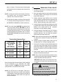
7.2 CONTROL PANEL
1
2
3
4
5
Figure 10
1. Water Temperature Gauge
2. Hour Meter
3. On/Off Switch
4. Starter Button
5. Oil Light
7.3 BEFORE STARTING ENGINE
WARNING
!
Always run unit engine where there is plenty of
fresh air to prevent a buildup of carbon monox-
ide fumes. Carbon monoxide is colorless,
odorless and deadly. NEVER run unit in an
enclosed space where exhaust fumes will col-
lect.
Never use the unit in, or near an area where
there is dust or fumes in the air which may be
explosive. The electrical and exhaust systems
of this unit will make sparks which could ignite
explosive materials.
DO NOT operate unit over any hard surfaces
(driveways, sidewalks, etc.) with aerator heads
in lowered position.
Always stop engine and DO NOT smoke or
allow open flames or sparks when refueling.
Gasoline is extremely flammable and highly
explosive under certain conditions.
WARNING
!
DO NOT place hands or feet beneath unit at any
time, unless engine is shut off and yellow
uplatch bar is securing unit in “UP” position.
Always use good judgment when operating on
or near hills or slopes. NEVER start or stop
suddenly. NEVER change direction of unit
abruptly or make sharp turns on slopes.
ALWAYS drive straight up and down the face
of slopes, NEVER across the face of slopes.
NEVER attempt to aerate in reverse.
NOTE: Use extreme care when backing unit. DO NOT
back unit with aerator in DOWN position. The tines
and tine rams may be severely damaged.
1. Check engine oil level with aerator heads lowered
and add oil if necessary. See engine oil section for
type and quantity of oil.
2. Fill GA–60 fuel tank with gasoline. See fuel section
for type and quantity of fuel.

7 OPERATION
14
7.4 GA–60 STARTING PROCEDURE
1. Set ON/OFF toggle switch in “ON” position and
depress start button. Release start button as soon as
engine starts. Allow approximately 5 minutes warm
up time for engine before beginning aerating.
NOTE: NEVER depress start button while engine is run-
ning. Starter drive and flywheel ring may be dam-
aged.
CAUTION
!
To prevent possible breakage of hydraulic lift cylin-
der brackets on frame, unit MUST BE resting on
down stops while aerating.
NEVER use the hydraulic lift cylinder to adjust
depth of aeration.
7.5 BEGINNING AERATION
WARNING
!
BE SURE electric brakes are working properly
before beginning aeration. NEVER operate the
GA–60 if the brakes are not adjusted correctly.
Refer to electric brakes section.
1. Place the governor control lever in “DOWN” position.
2. Depress foot throttle pedal down to the floorboard.
3. Refer to decal to obtain desired RPM and hole spac-
ing for the Turf Truckster you are operating.
Decal 1: is for all Trucks manufactured prior to Aug.
1998. (Check ID plate for year of manufacture.)
Decal 2: is for Trucks with a 660 engine and manual
transmission.
Decal 3: is for Trucks with a 970 or diesel engine with
manual transmission.
Decal 4: is for Trucks with a 660 engine and auto-
matic transmission.
4. Raise foot from throttle pedal to allow engine to
return to idle speed.
5. Depress clutch pedal and place transmission gear
selector in FIRST gear.
NOTE: Aerating in a higher gear will damage the aerat-
ing mechanism and will also result in poor hole qual-
ity.
6. Shift Turf–Truckster auxiliary transmission into LOW
range.
7. Slowly release clutch pedal to engage clutch while
depressing foot throttle.
8. After reaching desired engine RPM’s, slowly push
hydraulic flow control lever down to lower aerating
heads and begin aeration.
845440
3000
3500
4000
4400
MM.
90
100
115
125
(INCH)
(3 1/2)
(4)
(4 1/2)
(5)
N/MIN
660CC
845442
2800
3200
3600
4000
MM.
90
100
115
125
(INCH)
(3 1/2)
(4)
(4 1/2)
(5)
N/MIN
845441
2100
2400
2700
3000
MM.
90
100
115
125
(INCH)
(3 1/2)
(4)
(4 1/2)
(5)
N/MIN
660CC
1600
1800
2100
2300
MM.
90
100
115
125
(INCH)
(3 1/2)
(4)
(4 1/2)
(5)
N/MIN
840892
DECAL 1
DECAL 2
DECAL 3
DECAL 4

OPERATION 7
15
7.6 AERATING DEPTH ADJUSTMENT
The GA–60 is designed to aerate at a MAXIMUM depth
of 4” (102 mm). The operator should be aware that, in
extremely hard soil, the machine may not be capable of
pushing the tines 4” (102 mm) into the ground. DO NOT
operate with the depth setting at the 4” (102 mm) maxi-
mum when the tines are only penetrating 2–3 inches
(51–76 mm). Operating under these conditions will
cause premature wear and/or broken components in the
aerator linkage. If the aerator tires consistently ride up off
the turf or bounce up off the turf, the ground is too hard.
NEVER try to aerate at a depth greater than the soil
conditions will allow. The operator must first make a test
run, measure the depth of the holes, and set the depth
adjustment to correspond. After aerating the area once
or twice at that depth to loosen the sub–soil, it may be
possible to lower the settings each time until the 4” (102
mm) maximum depth can be accomplished without
abusing the GA–60.
AGAIN––Aerate a small test plot, measure the depth of
the hole and adjust the depth setting on the GA–60 to
match it.
If aerating extremely hard soil, additional penetration is
possible with added water, either by rain or irrigation.
Moist ground is easier to aerate than dry ground and is
also easier on the aerator mechanism.
If aerating in soil with rocks or stones, additional penetra-
tion over time may not be possible. The operator must
determine what depth is possible for that area and be
sure he does not exceed that depth.
Adjusting the depth from 2 1/2” (64 mm) to 4” (102 mm) is
accomplished by adjusting the 1/2” (13 mm) axle stop
spacers shown in Figure 11.
1
2
Figure 11
1. Downstop Block
2. Spacers

8 MAINTENANCE
16
8 SERVICE AND MAINTENANCE
WARNING
!
When performing service or maintenance work on the
GA 60, ALWAYS lock the uplatch bar in place to pre-
vent the aeration heads from being lowered acciden-
tally or due to a loss in hydraulic pressure. Set the
park brake on the tractor.
If any type of work is to be performed on the GA 60,
disconnect the power cord and remove the key from
the towing vehicle. This will prevent the GA 60 and the
towing vehicle from being accidentally started.
When replacement parts are required, use genuine
RYAN parts or parts with equivalent characteristics
such as type, strength and material. Failure to do so
may result in product malfunction and possible injury
to the operator and/or bystanders.
NEVER attempt to perform service or maintenance
functions on the GA 60 if you are UNTRAINED or
UNAUTHORIZED. Improper maintenance can and will
cause hazardous conditions. For necessary mainte-
nance and service, contact your authorized RYAN
dealer.
When it is necessary to raise the GA 60PT for any
repair or service, use jackstands to help provide ade-
quate support. DO NOT rely on hydraulic or mechani-
cal jacks for support.
Immediately replace any warning and/or safety decal
that becomes damaged or difficult to read.
To reduce hazard of fire, always keep engine free of
excessive grease. If fuel system leakage is detected,
repair leak immediately. DO NOT operate unit until
leak is repaired. ALWAYS stop engine and do not
allow open flames or sparks when performing any
maintenance function involving gasoline.
This product is heavy equipment and may present a
crush hazard unless safety precautions are taken.
DO NOT operate equipment without all shields and
guards in place.
To prevent possible injury, keep bystanders a safe
distance away from machinery.
DO NOT make any adjustments or perform any main-
tenance while the engine is running.
BE SURE to read the service section of this operators
manual and the parts and maintenance manual prior
to performing any service work on this product.

MAINTENANCE 8
17
8.1 DAILY MAINTENANCE
1 Check the tire pressure (18 psi, 124 kPa).
2 BE SURE the weight is off of the tires. Lubricate axle
pivots with a standard lithium based grease.
3 Lubricate aerator drive chains with chain lubricant
spray (Part No. 523248).
4 Lubricate belt idler pivot with a standard lithium
based grease.
5 Lubricate clutch linkage bellcrank with a standard
lithium based grease.
6 Clean radiator intake screen.
7 Check radiator coolant level.
8 Check engine oil level.
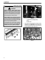
LUBRICATION
1. Clutch Linkage
2. Belt Idler
3. Axle Yoke
4. Axle Yoke
5. Axle Yoke
⊗
⊗
⊗
⊗
⊗
1
2
3
4
5
CHART
8.2 LUBRICATION FITTINGS
There are five (5) lubrication fittings that should be lubri-
cated daily with a standard lithium based grease.
Three (3) fittings are located on the rear axle yoke
assemblies. Refer to Figure 12 for lubrication points.
NOTE: When lubricating the rear axle yoke assemblies,
the wheels should be off the ground and the weight
should be off the rear axle to allow proper lubrication
of the yoke.
One (1) fitting is located on the clutch linkage pivot tube,
and the fifth is located at the drive belt idler pivot.
The four (4) drive chains in the aerator head assembly
should be sprayed with chain lubricant, spray (Part No.
523248) each time the GA 60 is refueled, to greatly
extend chain life.
1
2
3
4242
FIGURE 12
1. Belt Idler Lube Fitting
2. Clutch Linkage Lube Fitting
3. Axle Yoke Lube Fittings (3)

8 MAINTENANCE
18
8.3 AIR CLEANER
This is a large capacity, dry type air cleaner with a
replaceable paper element.
8.4 CHECKING ELEMENT
Check element for damage, pin holes, etc. by placing a
light source such as a flashlight inside.
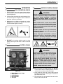
8.5 INSTALLING ELEMENT
1. Clean dust from inside of housing with a damp cloth.
BE SURE dust does not enter intake.
2. Check all gaskets to make sure they are not loose or
damaged.
3. Insert element into housing as shown in Figure 13.
4. Apply a light grease film to the nylon washer and
wing nut. Secure element with washer and wing nut.
NOTE: The dust collector empties automatically when
properly installed with collector pointing DOWN.
Refer to Figure 14 for proper positioning.
1
2
Figure 13
1. Filter Element
2. Filter Housing
1
2
Figure 14
1. Filter Assembly
2. Dust Collector
Page is loading ...
Page is loading ...
Page is loading ...
Page is loading ...
Page is loading ...
Page is loading ...
Page is loading ...
Page is loading ...
-
 1
1
-
 2
2
-
 3
3
-
 4
4
-
 5
5
-
 6
6
-
 7
7
-
 8
8
-
 9
9
-
 10
10
-
 11
11
-
 12
12
-
 13
13
-
 14
14
-
 15
15
-
 16
16
-
 17
17
-
 18
18
-
 19
19
-
 20
20
-
 21
21
-
 22
22
-
 23
23
-
 24
24
-
 25
25
-
 26
26
-
 27
27
-
 28
28


Ransomes 544913 Owner's manual
- Category
- Mini tillers
- Type
- Owner's manual
Ask a question and I''ll find the answer in the document
Finding information in a document is now easier with AI
Related papers
-
Ransomes 898558A Owner's manual
-
-
-
-
-
-
-
 ryan 544872 User manual
-
-

Other documents
-
Tekonsha 118240† Installation guide
-
Toro 30in Stand-On Aerator User manual
-
Toro 21in Walk-Behind Aerator User manual
-
-
-
-
-
-
-