Mitsubishi Heavy Industries RC-EXZ3A User manual
- Category
- Split-system air conditioners
- Type
- User manual

REMOTE CONTROL
RC-EXZ3A
USER'S MANUAL
Thank you very much for your purchasing the REMOTE CONTROL for our
packaged air conditioner.
This user's manual describes cautions for safety. Please read this manual carefully before use in order to operate the unit properly.
Keep this manual, after reading, at a safe place where you can consult it whenever it is necessary.
When the ownership of the unit is changed, please be sure to transfer this manual and the
“
Installation Manual
”
to a new owner.
It is not recommended for a user to install or move the unit by the user's own discretion. (Safety or functions may not be assured.)
PJZ012A185
201907
ORIGINAL INSTRUCTIONS


- 1 -
Contents
1. Before you use 2
Safety precautions ………………………………… 2
Precautions for waste disposal …………………… 3
Unit specications ………………………………… 3
Names and functions of sections on the R/C ………… 4
Menu item ………………………………………… 7
2. Menu items 9
Run ……………………………………………… 9
Stop ……………………………………………… 9
Change operation mode ………………………… 10
Change set temp ……………………………… 10
Change ap direction ……………………………… 11
Change the fan speed …………………………… 14
Zone ON/OFF operation …………………………… 14
Zone name setting ………………………………… 15
F1/F2 switch operation …………………………… 16
Anti draft ON/OFF operation ……………………… 17
High power operation ……………………………… 18
Energy-saving operation …………………………… 19
3. Quick reference of menu items 20
Quick reference of menu items …………………… 20
Restrictions on the sub R/C ………………………… 22
Operations on menu screens ……………………… 23
Cautions for each setting screen …………………… 24
4. Settings and operations 25
Energy-saving setting ……………………………… 25
Individual ap control ……………………………… 31
Anti draft setting …………………………………… 35
Ventilation operation ……………………………… 37
Initial settings ……………………………………… 38
Timer …………………………………………… 42
Weekly timer ……………………………………… 50
Home leave mode ………………………………… 54
Registering favorite settings ……………………… 57
Favorite setting operation ………………………… 58
Administrator settings ……………………………… 59
Silent mode control ………………………………… 72
Select the language ……………………………… 73
Filter sign reset …………………………………… 74
5. Maintenance of unit and LCD 75
Maintenance of unit and LCD ……………………… 75
6. Useful information 76
Contact company & Error display …………………… 76
7. Notice of inspection date 77
8. Message display 77
9. After-sale service 81
Please turn on the power switch 6 hours before
operation to protect the air conditioner (the crank case
heater is conducted and the compressor is heated).
Also, be sure not to turn off the power switch (the
crank case heater is conducted and the compressor
is heated during stop of the compressor. It protect the
fault of the compressor caused by liquid refrigerant
stagnation).
Note

- 2 -
1. Before you use
Safety precautions
●Please read the precautions written here carefully to operate the unit properly.
You are required to observe these fully because every item of these instructions is important for safety.
WARNING
Failure to follow these instructions may result in serious consequences
such as death, severe injury, etc.
CAUTION
Failure to follow these instructions may cause injury, property damage or, serious
consequences depending on.
●The following pictograms are used in the text.
Never do. Always follow the instructions given.
Absolutely keep water away. Absolutely keep wet hands away.
● Keep this manual at a safe place where you can consult with whenever necessary. Show this
manual to installers when moving or repairing the unit. When the ownership of the unit is
transferred, this manual should be given to a new owner.
Electrical wiring work must be implemented only by qualified specialists.
WARNING
Consult your dealer or a professional contractor to install the unit.
Improper installation made on your own may cause electric shocks, re or dropping of the unit.
Consult your dealer when moving, disassembling or repairing the unit.
Never modify the unit.
Improper handling may result in injury, electric shocks, re, etc.
Avoid using combustible substances (hair spray, insecticide, etc)
near the unit.
Do not use benzene or paint thinner to clean the unit.
It could cause cracks, electric shocks or re.
Stop operation under abnormal situation.
If continued, it could result in break-down, electric shocks, re, etc.
If any abnormal condition (burnt odor etc.) occurs, stop operation, turn off the power
switch and consult your dealer.
This appliance can be used by children aged from 8 years and above
and persons with reduced physical, sensory or mental capabilities or
lack of experience and knowledge if they have been given supervision
or instruction concerning use of the appliance in a safe way and
understand the hazards involved.
CAUTION
Do not use or let use the unit or remote control as play equipment.
Improper operations could cause ill health or health disorder.

- 3 -
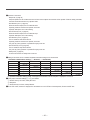
Unit specifications
Precautions for waste disposal
Your Air Conditioning product may be marked with this symbol. It means that waste electrical and
electronic equipment (WEEE as in directive 2012/19/EU) should not be mixed with general
household waste. Air conditioners should be treated at an authorized treatment facility for re-use,
recycling and recovery and not be disposed of in the municipal waste stream. Please contact the installer
or local authority for more information.
Never disassemble the remote control.
If you touch internal parts accidentally, you could get electric shocks or cause trouble.
Consult your dealer when it is necessary to inspect its interior.
Do not wash the remote control with water or liquid.
It could cause electric shocks, re or break-down.
Do not touch electric parts or operate buttons or screens with wet hands.
It could cause electric shocks, re or break-down.
Do not dispose the remote control by yourself.
It could destruct the environment. Ask your dealer when it is necessary to dispose the
remote control.
Note
The remote control should not be installed where it is exposed to
direct sunlight or the ambient temperatures become higher than 40 C
or lower than 0 C.
It could cause deformation, discoloration or break-down.
Do not use benzene, paint thinner, wipes etc. to clean the remote control.
It could discolor or break-down the remote control. Wipe it with a piece of cloth which is
squeezed tightly after wetting with diluted neutral detergent. Finish up the cleaning by
wiping with a piece of dry cloth.
Do not pull or twist the cable of the remote control.
It could cause break-down.
Do not tap the remote control buttons or screen with pointed objects.
It could damage or cause break-down.
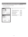
Item Description
Product dimensions 120 (W) x 120 (H) x 19 (D) mm (not including protruded section)
Weight 0.20 kg
Power supply DC 18 V
Power consumption 0.6 W
Usage environment Temperature: 0 to 40
°
C
Material Casing: ABS

- 4 -
Run/Stop
switch
One push on the button starts operation and another
push stops operation. (☞page 9)
F1
switch
F2
switch
This switch starts operation that is set in F1/F2
function setting (☞page 71).
(☞page 16)
Operation lamp
This lamp lights in green (yellow-green) during
operation. It changes to red (orange) if any error
occurs.
Operation lamp luminance can be changed.
(☞page 42)
LCD (With backlight)
A tap on the LCD lights the backlight.
The backlight turns off automatically if there is no
operation for certain period of time.
Lighting period of the backlight lighting can be
changed. (☞page 41)
If the backlight is ON setting, when the screen is
tapped while the backlight is turned off, the backlight
only is turned on. (Operations with switches ①, ②
and ③ are excluded.)
USB port
USB connector (mini-B) allows connecting to a
personal computer.
For operating methods, refer to the instruction
manual attached to the software for personal
computer (remote control utility software).
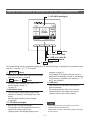
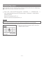
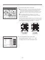
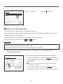
Touch panel system, which is operated by tapping the LCD screen with a nger, is employed for any operations other
than the ① Run/Stop, ② F1 ③ F2 switches.
LCD (With backlight)
Names and functions of sections on the R/C
(Operating section)
F2 switch
Operation lamp
USB port (mini-B)
Run/Stop
switch
F1
switch
Note
・ When connecting to a personal computer, do not connect
simultaneously with other USB devices.
Please be sure to connect to the computer directly, without going
t
hrough a hub, etc.

- 5 -
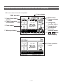
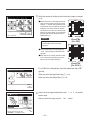
Names and functions of sections on the R/C (Display)
*All icons are shown for the sake of explanation.
F1 F2
switch
function display
Clock, Room name
display
Change operation
mode button
TOP screen
Timer button
Icon display
Menu button
Change set temp
button
Change flap
direction button
Change the fan
speed button
Select the
language button
Message display
Zone operation
button

- 6 -
Clock, Room name display
Displays the current time and the room name.
Icon display
Each icon is displayed when one of following settings is
going on.
When the demand
control is effective.
When setting is made
from the sub R/C.
When the central
control (Optional) is running.
When the periodical
inspection is necessary.
During the ventilation
operation.
When ”lter sign” is up.
When the Permission/
Prohibition setting is made.
When the peak-cut
timer is set.
When the weekly timer
is set.
Menu button
When setting or changing other than the following ④-⑧,
tap the menu button. Then menu items are displayed, select
one and set.
Change operation mode button
Displays the operation mode which is selected currently.
Tap this button to change the operation mode.
Change set temp button
Displays the temperature which is set currently. Tap this
button to change the set temperature.
Change flap direction button
Displays the ap direction which is selected currently. When the
3D auto ow operation is enabled, 3D auto display will appear.
Tap this button to change the ap direction.
Change the fan speed button
Displays the fan speed which is selected currently. Tap this button
to change the fan speed.
Timer button
Displays simplied contents of the timer which is set
currently.
(When two or more timers are set, contents of the timer
which will be operated immediately after is displayed.)
Tap this button to set the timer.
Select the language button
Select a language to be displayed on the R/C.
Zone operation button
Tap this button to go to the zone operation screen.
Message display
Status of air conditioner operation and messages of the
R/C operations etc. are displayed.
F1 F2
switch function Display
Displays the function that is set for each
F1 F2
switch.
The function for these switches can be changed in F1/F2
function setting.

- 7 -
Menu item
Main menu
Run ………………………………………………………………………………………… 9
S
top
………………………………………………………………………………………… 9
C
hange operation mode
………………………………………………………………… 10
C
hange set temp
………………………………………………………………………… 10
C
hange ap direction
…………………………………………………………………… 11
C
hange the fan speed
…………………………………………………………………… 14
Z
one ON/OFF operation
………………………………………………………………… 14
Zone name setting………………………………………………………………………… 15
F
1, F2 switch operation
…………………………………………………………………… 16
A
nti draft ON/OFF operation
…………………………………………………………… 17
H
igh power operation
…………………………………………………………………… 18
E
nergy-saving operation
………………………………………………………………… 19
Individual ap control ……………………………………………………………………… 31
An
ti draft setting …………………………………………………………………………… 35
Ti
mer
……………………………………………………………………………………… 42
S
et ON timer by hour
…………………………………………………… 44
S
et OFF timer by hour
………………………………………………… 46
Se
t ON timer by clock
…………………………………………………… 47
S
et OFF timer by clock
………………………………………………… 49
Conrm …………………………………………………………………… 50
F
avorite setting
…………………………………………………………………………… 57
W
eekly timer
……………………………………………………………………………… 50
H
ome leave mode ………………………………………………………………………… 54
E
xternal ventilation
……………………………………………………………………… 37
S
elect the language
……………………………………………………………………… 73
S
ilent mode control
……………………………………………………………………… 72
Sleep timer ………………………………………………………………………………… 25
P
eak-cut timer
…………………………………………………………………………… 26
A
utomatic temp set back
………………………………………………………………… 29
M
otion sensor control
…………………………………………………………………… 30
Filter sign reset …………………………………………………………………………… 74
Initial settings ……………………………………………………………………………… 38
Clo
ck setting
…………………………………………………………… 38
D
ate & time display
……………………………………………………… 39
S
ummer time
…………………………………………………………… 40
Co
ntrast
………………………………………………………………… 40
B
acklight
………………………………………………………………… 41
C
ontroller sound
………………………………………………………… 41
Operation lamp luminance ……………………………………………… 42
A
dministrator settings
…………………………………………………………………… 59
P
ermission/Prohibition setting
………………………………………… 60
Ou
tdoor unit silent mode timer
………………………………………… 61
S
etting temp range
……………………………………………………… 62
T
emp increment setting
………………………………………………… 64
S
et temp display
………………………………………………………… 64
R/C display setting ……………………………………………………… 65
C
hange administrator password
……………………………………… 70
F
1/F2 function setting
…………………………………………………… 71
Basic operation
Useful functions
Energy-saving setting
Filter
User setting

- 8 -
Main menu
Installation settings
I
nstallation date
………………………………………………………… 29
C
ompany information
…………………………………………………… 29
Te
st run
…………………………………………………………………… 29
D
uct unit settings
………………………………………………………… 29
C
hange auto-address
…………………………………………………… 29
A
ddress setting of main IU
……………………………………………… 29
IU back-up function ……………………………………………………… 29
M
otion sensor setting
…………………………………………………… 29
R
/C function settings
Mai
n/Sub of R/C
………………………………………………………… 29
R
eturn air temp
………………………………………………………… 29
R
/C sensor
……………………………………………………………… 29
R
/C sensor adjustment
………………………………………………… 29
Operation mode ………………………………………………………… 29
º
C / ºF
…………………………………………………………………… 29
F
an speed ……………………………………………………………… 29
E
xternal input
…………………………………………………………… 29
U
pper/lower ap control
………………………………………………… 29
L
eft/right ap control
…………………………………………………… 29
V
entilation setting
……………………………………………………… 29
Auto-restart ……………………………………………………………… 29
A
uto temp setting
……………………………………………………… 29
A
uto fan speed ………………………………………………………… 29
IU
settings
F
an speed setting
……………………………………………………… 29
F
ilter sign
………………………………………………………………… 29
E
xternal input 1
………………………………………………………… 29
External input 1 signal …………………………………………………… 29
E
xternal input 2
………………………………………………………… 29
E
xternal input 2 signal
…………………………………………………… 29
Heating thermo-OFF temp adjustment ……………………………………………… 29
Return temperature adjustment ………………………………………… 29
Fan control in cooling thermo-OFF
……………………………………… 29
Fan control in heating thermo-OFF
……………………………………… 29
An
ti-frost temp
…………………………………………………………… 29
A
nti-frost control
………………………………………………………… 29
D
rain pump operation
…………………………………………………… 29
Keep fan operating after cooling is stopped ……………………………………………………29
Keep fan operating after heating is stopped
……………………………………… 29
Intermittent fan operation in heating
……………………………………… 29
F
an circulator operation
………………………………………………… 29
C
ontrol pressure adjust
………………………………………………… 29
A
uto operation mode
…………………………………………………… 29
T
hermo. rule setting
…………………………………………………… 29
A
uto fan speed control ………………………………………………… 29
I
U overload alarm
……………………………………………………… 29
External output setting ………………………………………………… 29
S
ervice & Maintenance
IU
address
……………………………………………………………… 29
N
ext service date………………………………………………………… 29
Op
eration data
…………………………………………………………… 29
E
rror display
……………………………………………………………… 29
S
aving IU settings
……………………………………………………… 29
Special settings ………………………………………………………… 29
I
ndoor unit capacity display
…………………………………………… 29
Contact company ………………………………………………………………………… 76
Service setting
Contact company
Please refer to the
installation manual.
Please refer to the
installation manual.
Please refer to the
installation manual.
Please refer to the
installation manual.

- 9 -
Push the
Run/Stop
switch.
Operation lamp (green) lights and operation starts.
When the operation stops, all operation buttons on the screen turn off.
When the set lighting time of backlight (
☞
page41) is counted up, the
backlight turns off.
When the screen is tapped, the backlight lights, and all operation buttons
are displayed.
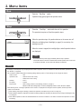
2. Menu items
Note
・ Do not shut down the power supply immediately after the stop of operation.
It should be waited for more than 5 minutes till the residual operation time of drain motor
i
s counted up. Otherwise, it could cause water leakage or breakdown.
・ A message
“
Invalid request
”
may be displayed when a button is pushed. This is not a fault but it is because the button operation is set to
the
“
Disable
”
. (☞page 60)
・ The unit starts to operate initially with the following settings after the power on. These settings can be changed as desired.
Central control …… OFF
Operation mode …… With auto mode: Auto cooling
…… Without auto mode: Cooling
Set temp …… 23.0
°
C
Fan speed …… 3-speed
Flap direction …… When cooling: position 2, when heating: position 3 (☞page 11)
*When an FDK with a left/right ap is connected, left/right ap direction: center, 3D AUTO: disabled
・ In the following cases, a message
“
Operation mode is invalid.
”
is displayed and it changes to the fan operation, because operation
modes are not matched.
① When Heating (including auto heating) is selected for Operation mode while using an OU for cooling only.
② When Heating is selected for Operation mode while controlling multiple units including units allowed for both cooling and heating and units
for cooling only.
③ When different operation modes are selected between IUs which are connected to a OU that do not allow mixed operation of cooling
and heating.
Advice
Press the
Run/Stop
switch while the unit is in operation.
The operation lamp turns off and the operation stops.
Stop
Run

- 10 -
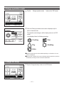
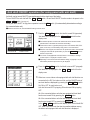
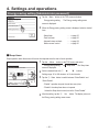
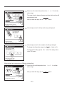
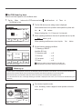
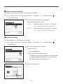
2
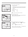
When the Change operation mode screen is displayed, tap the
button of desired mode.
The operation mode changes, and the display returns to the TOP
screen.
Icons displayed have the following meanings.
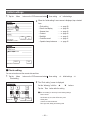
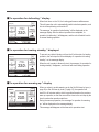
Change operation mode
■Operation modes which cannot be selected depending on combinations of IU and
OU are not displayed.
■When the Auto is selected, the cooling and heating switching operation is performed
automatically according to indoor and outdoor temperatures.
Cooling Fan
Dry Heating
Auto
Change operation mode
Fan
Heating
Back
Auto
Dry
OutdoorRoomR/C
Cooling
Please select operation mode.
1
Tap the Change operation mode button on the TOP screen.
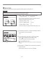
1
Tap the
Change set temp
button on the TOP screen.
Change set temp

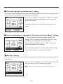
- 11 -
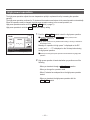
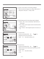
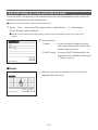
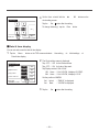
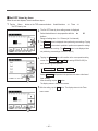
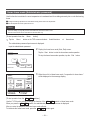
1
Tap the
Change ap direction
button on the TOP screen.
When an FDK with a left/right ap is not connected:
☞
2
When one or more FDKs with a left/right ap are connected:
☞
3
Change flap direction
Change ap direction
Ind. ap
Control
Auto swing
Back
OutdoorRoomR/C
Select the ap direction.
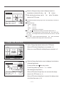
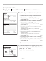
2
When the Change set temp screen is displayed, select the
temperature as desired with using
▲
▼
buttons.
3
After selecting the set temp, tap the
Set
button. The display
returns to the TOP screen.
■For allowable temperature setting ranges, refer to the range setting of set temp (☞
page 62).
■Reference set temp
Cooling
… 26 to 28°C
Dry
… 24 to 26°C
Heating
… 20 to 24°C
Fan
… Setting temp is not requi
red.
■
If the
Auto is selected for the set temp, the set temp display shows
“
0
”
.
Temperature can be adjusted higher or lower with using
▲ buttons. Note
that
Auto is not displayed and cannot be set when SC-SL2, SC-SL3, or SC-SL4
is connected.
■If the
Back button is tapped without tapping the Set button, the selected
set temp is invalidated and the display returns to the TOP screen.
Change set temp
Auto
Set
Back
OutdoorRoomR/C
Tap
▲▼
to set temp & tap [Set].
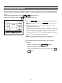
2
When the Change ap direction screen is displayed, tap the button
of desired ap direction.
T
o swing the ap, tap the
Auto swing
button.
T
o x the ap position, tap one of
1
to
4
buttons.
After selecting the ap direction,
When an FDK with a left/ right ap is not connected, the display
returns to the TOP screen. (
☞
1)
When an FDK with a left/right ap is connected, the display returns
to the Select ap screen. (
☞
3)

- 12 -
Change ap direction
Ind. ap
Control
Back
Select ap
Upper/lower ap
Back
Select the ap to change.
Left/right ap
3D AUTO
2
1
3
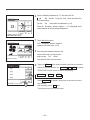
When one or more FDKs with a left/right ap are connected, the
Select ap screen is displayed. Select the desired ap direction.
①
To change the up/down ap direction, tap the
Upper/lower ap
button. The Change ap direction screen
for the up/down ap is displayed. (
☞
2)
②
To change the left/right ap direction, tap the
Left/right ap
button. The Change ap direction screen for the left/right ap is
displayed. (
☞
4)
③
The 3D auto ow operation automatically controls the fan speed
and ap direction to efciently condition the air of the entire room.
To switch to the 3D auto ow operation, tap
3D AUTO
to
enable the operation.
To disable the 3D auto ow operation, tap the
3D AUTO
again.
The ap direction returns to the direction that was set before the
3D auto ow operation was enabled. The 3D auto ow operation
will also be disabled when you change the up/down or left/right
ap direction during the 3D auto ow operation.
4
Tap the desired ap direction. After selecting the ap direction, the
display returns to the Select ap screen. (
☞
1)
5
When the 3D auto ow operation is enabled, “3D AUTO” is displayed
on the
Change ap direction
button, as shown on the left.
R/C Room
Outdoor
3

- 13 -
■When multiple IUs are connected to the remote control for a mixed environment consisting of FDKs with a left/right ap and IUs without a
left/right ap, enabling the 3D auto ow operation will set the models without a left/right ap to a ap position set before the 3D auto ow
operation was started.
■Since the ap is controlled automatically in the following operation, it may differ from the display on the R/C.
∙
When the room temperature is higher than the set temp (In case of the heating operation)
∙
When the
“
In operation for heating standby.
”
or
“
In operation for defrosting.
”
is displayed (In case of the heating operation).
Cool air is blown horizontally not to blow directly to human body.
∙
In a high humidity environment (during cooling operation)
■When you select Auto swing while the Anti draft setting (☞page 35) is enabled, the ap will not swing and be set at ap position
1 .
■Changing the left/right ap direction and 3D auto ow operation cannot be performed from the SC-SL2, SC-SL3, or SC-SL4. Also note that
3D auto ow operation will not be disabled when you change the ap direction from the SC-SL2, SC-SL3, or SC-SL4 during a 3D auto
ow operation.
Note
・ Do not manually move the aps or panel with anti draft by force. It could damage these aps and panels.
・ Do not blow air downward for a long period of time during the cooling operation. Condensation may be generated and water may drip from
the side panel. (In case of Ceiling suspended type)
・ For FDKs with a left/right ap, it is recommended that the ap should be set toward the right side when there is a wall on the left, or set
toward the left side when there is a wall on the right. For more information, refer to the Notes in the Individual ap control section (☞page
33).

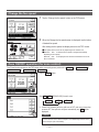
- 14 -
1
Tap the
Change the fan speed
button on the TOP screen.
2
When the Change the fan speed screen is displayed, tap the button
of desired fan speed.
After setting the fan speed, the display returns to the TOP screen.
■Fan speeds which can be set vary depending on the models of IU.
■When the
Auto is selected, the fan speed is changed automatically
depending on the capacity.
Note that
Auto is not displayed and cannot be set when SC-SL2 or SC-
SL3 is connected.
Change the fan speed
Change the fan speed
Back
OutdoorRoomR/C
Select the fan speed.
Auto
Tap the Zones button.
Zone ON/OFF operation (for zone control)
The "Zones" button appears on the TOP screen when zone settings were performed by
Menu
⇒
Service setting
⇒
Installation setting
⇒
Duct unit setting
⇒
Zone setting
.
Sets ON / OFF (OPEN/CLOSE) for each zone.
→
ON
→
OFF
→
SPL*1
*1: If there is no common zone, the spill zone is OFF, and one or more other
zone are OFF, the spill zone will open automatically and SPL
will be
displayed.
Common zone: A zone in which a damper is not installed. Spill zone: A zone in
which a damper open automatically.
Advice

- 15 -
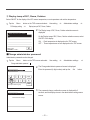
3
Tap the zone you want to set a zone name for.
Zone name setting (for zone control)
1
Tap the Menu button on the TOP screen and select User setting
⇒
Administrator settings .
The administrator password input screen is displayed.
Enter the administrator password.
2
When the administrator setting menu is displayed, select
R/C display setting
⇒
Zone name
.

- 16 -
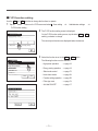
Changing the function of the F1 or F2 switch can be performed with the F1/F2 function setting (☞page 71).
The following functions are set as factory settings.
You may change these settings as desired.
F1
switch …High power operation
F2
switch …Energy-saving operation
F1/F2 switch operation
You can set any of the following functions to the F1 and F2 switches.
The F1
/ F2 switches act as shortcuts; it can be much easier and faster than starting an operation from the
usual Menu
on the TOP screen.
・High power operation …☞page 18
・Energy-saving operation …☞page 19
・Silent mode control …☞page 72
・Home leave mode …☞page 54
・Favorite setting operation …☞page 58
・Filter sign reset …☞page 74
・Anti draft ON/OFF …☞page 17
・ When using a standard FDT/FDTC panel (a panel without anti draft function), set functions other than the Anti draft ON/OFF function to
the
F1 and F2 switches. F1/F2 function setting (☞page 71)
If anti draft is turned on (operated) during the use of a standard FDT/FDTC panel, louvers may not automatically swing, which is not a malfunction.
Advice
4
The zone name input screen is displayed.
The zone name can be set with up to 8 2-byte letters (16 1-byte
letters).
You can enter alphanumeric or Cyrillic.
Tap the Back
or Next button to display next character group.
When you have nished inputting the room name, tap Set
.
5
The zone name that was set is displayed on the zone operation screen.

- 17 -
Anti draft ON/OFF operation (for using panel with anti draft)
Anti draft can be turned ON/OFF (operated/stopped) with a single tap of the button.
To turn ON/OFF the anti draft with the F1
or F2 switch, the anti draft ON/OFF function needs to be preset to the
F1
or F2 switch. (☞
page 71
)
Initially, Anti draft ON/OFF or high power operation is set to the F1
switch. (It is automatically determined according to
the connected indoor unit.)
■When the sub R/C is set, Anti draft ON/OFF setting cannot be used.
1
Push the
F1
(
F2
) switch. Anti draft is turned ON (operated).
“Anti draft ON” is displayed in the
F1
(
F2
) switch function
display area.
■The enabled operation mode and the enabled anti draft of the blow outlets
operate based on the details set in the Anti draft setting.
■If anti draft is turned on (operated) during the use of the standard FDT, FDTC
panel, louvers may not automatically swing, which is not a malfunction.
■While the unit is stopped, anti draft does not operate even when
“
Anti draft ON
”
is displayed. Anti draft will operate when you press the
Run/Stop
switch to
start the unit operation.
■If no indoor unit equipped with anti draft function is connected, a message
“
Invalid request.
”
is displayed on the R/C screen.
■Depending on how the Permission/Prohibition setting (☞page 60) is set, the
administrator password input screen may be displayed.
2
Press the F1
(
F2
)
switch. Anti draft is turned OFF (stopped).
“
Anti draft OFF
”
is displayed in the F1
(
F2
)
switch function
display area.
3
When two or more indoor units equipped with anti draft function are
connected to the R/C, the indoor unit No. and the ON/OFF state of
each anti draft are displayed by pressing the F1
(
F2
)
switch.
Set ON or OFF for each indoor unit.
Anti draft is turned OFF by tapping ON and turned ON by tapping
OFF
.
All of the connected indoor units that are equipped with anti draft
function are turned ON by pressing the All ON
button.
All of the connected indoor units that are equipped with anti draft
function are turned OFF by pressing the All OFF
button.
In the F1
(
F2
)
switch function display area, the anti draft ON/
OFF state of the indoor unit that has the smallest address among
the indoor units equipped with anti draft function is displayed.

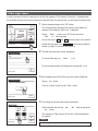
- 18 -
High power operation
The high power operation adjusts the room temperature quickly to a pleasant level by increasing the operation
capacity.
The high power operation continues for 15 minutes at the maximum and returns to the normal operation automatically.
When the operation mode is changed, the high power operation returns to the normal operation, too.
High power operation must be set to the F1
or F2 switch (☞page 71).
High power operation is set to the F1
switch as the factory setting.
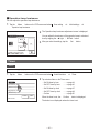
1
Push the
F1
(
F2
) switch to start the high power operation.
■Operation will start when the
F1
(
F2
) switch is pushed, even if
Run/Stop
switch is off.
■High power operation is only allowed when Heating or Cooling is selected for
the operation mode.
Message “In operation for high power.” is displayed on the R/C
screen, and “—, —°C” is displayed on the Set temp button during
the high power operation.
■Set temp and change fan speed operations are disabled during high power
operation.
2
High power operation is terminated when you perform one of the
following.
・
When you terminate through a
Run/Stop
operation
・
When you change the operation mode
・
When15 minutes have elapsed since the high power operation
started
・
When you terminate the high power operation with the
F1
(
F2
) switch
Menu
Direction
Cooling
15:50
(Mon)
F1: High power
Timer
In operation for high power.
Set temp
F2: Energy-saving
Page is loading ...
Page is loading ...
Page is loading ...
Page is loading ...
Page is loading ...
Page is loading ...
Page is loading ...
Page is loading ...
Page is loading ...
Page is loading ...
Page is loading ...
Page is loading ...
Page is loading ...
Page is loading ...
Page is loading ...
Page is loading ...
Page is loading ...
Page is loading ...
Page is loading ...
Page is loading ...
Page is loading ...
Page is loading ...
Page is loading ...
Page is loading ...
Page is loading ...
Page is loading ...
Page is loading ...
Page is loading ...
Page is loading ...
Page is loading ...
Page is loading ...
Page is loading ...
Page is loading ...
Page is loading ...
Page is loading ...
Page is loading ...
Page is loading ...
Page is loading ...
Page is loading ...
Page is loading ...
Page is loading ...
Page is loading ...
Page is loading ...
Page is loading ...
Page is loading ...
Page is loading ...
Page is loading ...
Page is loading ...
Page is loading ...
Page is loading ...
Page is loading ...
Page is loading ...
Page is loading ...
Page is loading ...
Page is loading ...
Page is loading ...
Page is loading ...
Page is loading ...
Page is loading ...
Page is loading ...
Page is loading ...
Page is loading ...
Page is loading ...
-
 1
1
-
 2
2
-
 3
3
-
 4
4
-
 5
5
-
 6
6
-
 7
7
-
 8
8
-
 9
9
-
 10
10
-
 11
11
-
 12
12
-
 13
13
-
 14
14
-
 15
15
-
 16
16
-
 17
17
-
 18
18
-
 19
19
-
 20
20
-
 21
21
-
 22
22
-
 23
23
-
 24
24
-
 25
25
-
 26
26
-
 27
27
-
 28
28
-
 29
29
-
 30
30
-
 31
31
-
 32
32
-
 33
33
-
 34
34
-
 35
35
-
 36
36
-
 37
37
-
 38
38
-
 39
39
-
 40
40
-
 41
41
-
 42
42
-
 43
43
-
 44
44
-
 45
45
-
 46
46
-
 47
47
-
 48
48
-
 49
49
-
 50
50
-
 51
51
-
 52
52
-
 53
53
-
 54
54
-
 55
55
-
 56
56
-
 57
57
-
 58
58
-
 59
59
-
 60
60
-
 61
61
-
 62
62
-
 63
63
-
 64
64
-
 65
65
-
 66
66
-
 67
67
-
 68
68
-
 69
69
-
 70
70
-
 71
71
-
 72
72
-
 73
73
-
 74
74
-
 75
75
-
 76
76
-
 77
77
-
 78
78
-
 79
79
-
 80
80
-
 81
81
-
 82
82
-
 83
83


Mitsubishi Heavy Industries RC-EXZ3A User manual
- Category
- Split-system air conditioners
- Type
- User manual
Ask a question and I''ll find the answer in the document
Finding information in a document is now easier with AI
Related papers
-
Mitsubishi Heavy Industries RC-EX3A Reference guide
-
Mitsubishi Heavy Industries RC-EX3 Reference guide
-
-
-
-
-
Mitsubishi Heavy Industries RCN-E2 User manual
-
-
-
Other documents
-
Friedrich 9368987053 User manual
-
Panasonic CZ-RWSC1U User manual
-
Fujitsu AOY90TPC3L Operating instructions
-
-
-
-
-
-
-