Page is loading ...

1) TURN OFF POWER.
IMPORTANT: Before you start, NEVER attempt any work without shutting off the
electricity until the work is done.
a) Go to the main fuse, or circuit breaker, box in your home. Place the main power
switch in the “OFF” position.
b) Unscrew the fuse(s), or switch “OFF” the circuit breaker switch(s), that control
the power to the fixture or room that you are working on.
c) Place the wall switch in the “OFF” position. If the fixture to be re placed has
a switch or pull chain, place those in the “OFF” position.
2) Attach chain to fixture. Fixture loop has one chain link factory installed.
Chain has one locking link at each end. Unscrew coupling on locking link
and slip over link attached to loop. Screw coupling closed.
3) Slip threaded ring (N) then canopy (M) onto chain (W)
4) Attach chain (with fixture connected) to bottom of screw collar loop
following the same procedure as in step 1.
5) Weave electrical wire, ground wire and safety cable through chain links
no more than 3 inches apart.
6) Pass electrical wire ground wire and safety cable through threaded ring (N),
canopy (M), one of the slots in screw collar loop (L) and into outlet box.
7) Pass safety cable through hole (See sec. 1)
8) In area above outlet box wrap cable around one of the 2 x 4’s erected
in section 1 and pull cable taut.
9) Secure cable with (2) clamps provided. NOTE: Cable is not to be used as the only
means of fixture support. Please follow independent mounting instructions completely.
10) Connect fixture ground wire and ground wire attached to threaded rod (B or P) to outlet box
ground wire with wire connector (not provided). Never connect ground wire to black or white
power supply wires.
11) Make wire connections (connectors not provided). Reference chart below for correct
connections and wire accordingly.
12) Raise canopy (M) to ceiling.
13) Secure canopy (M) in place by screwing threaded ring (N) onto screw collar loop (L)
1) APAGUE LA ALIMENTACIÓN ELÉCTRICA.
IMPORTANTE: Antes de comenzar, NUNCA trate de trabajar sin antes
desconectar la corriente hasta que el trabajo se termine.
a) Vaya a la caja principal de fusibles, o interruptor o caja de
circuitos de su casa. Coloque el interruptor de la corriente
principal en posición de apagado “OFF”.
b) Desatornille el (los) fusible (s), o coloque el interruptor o
interruptores
del breaker en posición de apagado “OFF”, que controla (n) la
corriente hacia el artefacto o habitación donde está trabajando.
c) Coloque el interruptor de pared en posición de apagado “OFF”.
Si el artefacto que se va a reemplazar tiene un interruptor o
cadena que se jala, colóquelos en la posición de apagado “OFF”.
2) Una la cadena (W) al artefacto. La argolla del artefacto tiene un
eslabón de cadena instalado de fábrica. La cadena tiene un eslabón
de cierre (X) en cada extremo. Desatornille el acoplamiento en el
eslabón de cierre y deslícelo sobre el eslabón unido a la argolla.
Atornille el cople para cierre.
3) Deslice el anillo roscado (N), luego el escudete (M) en la cadena (W).
4) Una la cadena (con el artefacto conectado) a la parte inferior de la
argolla con rosca (L), siguiendo el mismo procedimiento que en el
paso 1.
5) Intercale el alambre de corriente eléctrica y el de conexión a tierra
por los eslabones a una distancia de separación no mayor a
3 pulgadas (7.6 cm).
6) Pase el alambre de conexión a la corriente y el de conexión a tierra a
través del anillo roscado (N), el escudete (M), la varilla roscada (B)
dentro de la argolla con rosca (L) y dentro de la caja de salida.
7) Pase el cable de soporte a través del orificio (Vea la sección 1.)
8) En la zona arriba de la caja de salida haga enrede el cable alrededor
de una de las vigas de 2 x4´ instaladas en la sección 1 y jale el cable
tensionándolo.
NOTE: NEC CODE (314.24) requires that ceiling outlet boxes in the United States support up to 50 lbs. This fixture exceeds 50 lbs. and
must be installed using an outlet box approved for up to 100 lbs. or independently of the existing outlet box. Installation hardware and
instructions are provided for both.
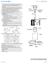
MOUNTING TO A 100 lb. MAX. APPROVED OUTLET BOX
1) Support cable from fixture (see sec. 3) must pass through outlet box. Drill 3/16” diameter
hole in outlet box if no other holes are available.
2) Screw threaded rod (B) from parts bag into pipe coupling (A) until threaded rod is flush
with top of pipe coupling. Secure in place by tightening allen head screw (C) with provided
wrench.
3) Pass threaded pipe (B) through mounting strap (D).
4) Screw hexnut (H) onto threaded rod (B).
5) Slip ground lug (F) and lockwasher (J) onto threaded rod (B).
6) Thread screw collar loop (L) onto threaded rod (B) until threaded
rod is flush with hole on lower side of screw collar loop.
7) Secure screw collar loop (L) in place by tightening
hexnut (H) down against groundlug (F),
lockwasher (J) and screw collar loop.
8) Assemble mounting strap (D) and assembled parts
to outlet box using screws provided with outlet box.
9) Trial fit canopy (M) over screw collar loop.
Approximately one half of the screw collar
loop exterior threads should be exposed below
canopy. To increase length of assembly loosen
hexnut (H) and unscrew screw collar loop no
more then two complete turns. To shorten,
loosen allen head screw (C). Screw threaded
pipe into coupling until desired height is met.
10) After desired position is found, remove
canopy and tighten allen head screw (C) and anti-rotational
screw located next to center hole inside mounting strap (D).
NOTA: El CÓDIGO ELÉCTRICO NACIONAL (NEC, por sus siglas en inglés) (314.24)
requiere que las cajas de salida para techo que se utilizan en los Estados Unidos
soporten una carga de hasta 50 lb (22.7 kg). Este artefacto tiene un peso superior a 50 lb,
por lo tanto debe instalarse usando una caja de salida que esté aprobada para usarse
con cargas de hasta 100 lb (45.4 kg) o independientemente de la caja de salida existente.
A continuación se le proporcionan el equipo e instrucciones de instalación para las
diferentes cajas de salida.
MONTAJE A UNA CAJA DE SALIDA APROBADA PARA
UN PESO MÁXIMO DE 100 lb (45.4 kg)
1) El cable de apoyo del artefacto (vea la Sección 3) debe pasar a través
de la caja de conexiones. Perfore un agujero de 3/16” de diámetro en
la caja de conexiones si no tiene otros agujeros disponibles.
2) Atornille la varilla roscada (B) que se suministra en la bolsa de las partes,
en el cople para tubo (A) hasta que la varilla esté al ras de la parte superior
del cople. Asegúrela apretando el tornillo de cabeza allen (C) con las llaves
que se le proporcionan para este fin.
3) Pase la varilla roscada (B) por la barra o soporte de montaje (D).
4) Atornille la tuerca hexagonal (H) en la varilla roscada (B).
5) Deslice la rondana plana con el cable para tierra (F) y la rondana de seguridad (J) en la varilla roscada (B).
6) Atornille la argolla con rosca en la varilla roscada (B) hasta que esté la varilla al ras del orificio que se encuentra en la parte inferior
de la argolla con rosca.
7) Asegure la argolla con rosca (L) en su lugar apretando la tuerca hexagonal (H) presionando contra la rondana plana con el cable
para tierra (F), la rondana de seguridad (J) y la argolla con rosca.
8) Ensamble la barra de montaje (D) y las partes ensambladas a la caja de salida usando los tornillos que se proporcionan con la caja.
9) Haga la prueba de ajuste colocando el escudete de techo (M) sobre la argolla con roscado.Aproximadamente la mitad de las
roscas exteriores de la argolla deberán estar expuestas por debajo del escudete. Para alargar el ensamble, afloje la tuerca
hexagonal (H) y gire para destornillar la argolla con rosca, no más de dos vueltas completas. Para acortar, afloje el tornillo de
cabeza allen (C). Atornille la varilla roscada en el cople hasta alcanzar la altura deseada.
10) Una vez que se tiene la posición deseada, quite el escudete y apriete el tornillo de cabeza allen (C) y el tornillo contra la rotación
localizado junto al orificio central al interior de la barra de montaje (D).
U.L. APPROVED 100LB. MAX.
OUTLET BOX AND HARDWARE
(SOLD SEPARATELY)
C
A
D
B
H
F
J
L
M
Connect Black or
Red Supply Wire to:
Connect
White Supply Wire to:
Black White
*Parallel cord (round & smooth)
*Parallel cord (square & ridged)
Clear, Brown, Gold or Black
without tracer
Clear, Brown, Gold or Black
with tracer
Insulated wire (other than green)
with copper conductor
Insulated wire (other than green)
with silver conductor
*Note: When parallel wires (SPT I & SPT II)
are used. The neutral wire is square shaped
or ridged and the other wire will be round in
shape or smooth (see illus.)
Neutral Wire
Conectar el alambre de
suministro negro o rojo al
Conectar el alambre de
suministro blanco al
Negro Blanco
*Cordon paralelo (redondo y liso)
*Cordon paralelo (cuadrado y estriado)
Claro, marrón, amarillio o negro
sin hebra identificadora
Claro, marrón, amarillio o negro
con hebra identificadora
Alambre aislado (diferente del verde)
con conductor de cobre
Alambre aislado (diferente del
verde) con conductor de plata
*Nota: Cuando se utiliza alambre paralelo
(SPT I y SPT II). El alambre neutro es de forma
cuadrada o estriada y el otro alambre será de
forma redonda o lisa. (Vea la ilustracíón).
Hilo Neutral
STRUCTURAL BRIDGING
MEMBER
MIEMBRO DE CONEXIÓN
ESTRUCTURAL
SAFETY CABLE
CABLE DE APOYO
CLAMP
GRAMPA
M
N
W
X
L
P
1A
3
Date Issued: 8/7/15 IS-42396-US
We’re here to help 866-558-5706
Hrs: M-F 9am to 5pm EST
9) Fije el cable con dos (2) abrazaderas mismas que se proporcionan.
NOTA: No deberá usar el cable como único medio de soporte del artefacto.
Por favor siga las instrucciones de montaje independiente por completo.
10) Conecte el alambre de conexión a tierra del artefacto y el alambre de
conexión a tierra de la varilla roscada (B), al alambre de tierra de la caja
de salida con el conector (no se proporciona). Nunca conecte el alambre
de tierra a los alambres blanco o negro del suministro de corriente.
11) Haga las conexiones de los alambres (no se suministran los conectores).
Refiérase a la tabla de abajo para realizar las conexiones correctas de
los cables.
12) Suba el escudete (M) hasta el techo.
13) Fije el escudete (M) en su lugar atornillando el anillo roscado (N) en
argolla con rosca (L).

MOUNTING TO A STANDARD OUTLET BOX
MEANS OF SUPPORT MUST BE ERECTED ABOVE OUTLET BOX. BELOW IS ONE SUGGESTED METHOD.
1) Screw threaded rod (P) from parts bag into pipe coupling (A) until threaded
pipe is flush with top of pipe coupling. Secure in place by tightening
allen head screw (C) with provided wrench.
2) Slip mounting strap (D) over provided 1/2-13UNC threaded rod (P).
3) Remove knockout in top of outlet box.
4) Support cable from fixture (see sec. 3) must pass through outlet box.
Drill 3/16” diameter hole in outlet box if no other holes are available.
5) In area above outlet box pass threaded rod (P) through hole in center
of outlet box.
6) Lay a 2x4 across ceiling joist on either side of threaded rod (P).
7) Secure 2x4’s in place by toe-nailing or other means.
8) Screw hexnut (H) onto threaded rod (P).
9) Slip ground lug (F) and lockwasher (J) onto threaded rod (P).
10) Thread screw collar loop (L) onto threaded rod (P) until threaded
pipe is flush with hole on lower side of screw collar loop.
11) Secure screw collar loop (L) in place by tightening hexnut (H) down
against ground lug (F), lockwasher (J) and screw collar loop.
12) Temporarily slip canopy (M) over screw collar loop (L). Approximately
one half of the screw collar loop exterior threads should be exposed
below canopy.
13) Temporarily screw threaded ring (N) onto screw collar loop (L).
14) In area above outlet box pull up on threaded rod (P) until canopy
is snug against ceiling.
15) Slide mounting strap (D) down threaded rod (P) and against 2x4’s.
16) Screw pipe coupling (A) down threaded rod (P) until pipe coupling is
snug against mounting strap (D) and canopy (M) is snug against ceiling.
17) Tighten allen head screw (C).
18) Secure mounting strap (D) in place by laying diagonally across both
2x4’s and driving two #10 x 1” sheet metal or equivalent screws
(not provided) through holes at ends of mounting strap. Tighten
anti-rotational hex screw located next to center hole inside mounting
strap (D) with provided allen wrench. NOTE: Mounting strap (D) must
be secured to prevent rotation.
19) Remove threaded ring (N) and canopy (M).
LOS ADITAMENTOS DE SOPORTE DEBEN INSTALARSE SOBRE LA CAJA
DE SALIDA. A CONTINUACIÓN SE SUGIERE UN MÉTODO DE INSTALACIÓN
1) Atornille la varilla roscada (P) que se suministra en la bolsa de las partes,
en el cople para tubo (A) hasta que el tubo roscado esté al ras de la parte
superior del cople. Asegúrelo en su lugar apretando el tornillo de cabeza
allen (C) con la llave que se proporciona para tal propósito.
2) Deslice la barra de montaje (D) sobre la varilla roscada (P) tipo 1/2 -13 UNC.
3) Retire el agujero ciego localizado arriba de la caja de salida.
4) El cable de apoyo del artefacto (vea la Sección 3) debe pasar a través de la caja de conexiones. Perfore un agujero de 3/16” de
diámetro en la caja de conexiones si no tiene otros agujeros disponibles.
5) Pase la varilla roscada (P) por arriba de la caja de salida a través del orificio central de la caja de salida.
6) Coloque una viga de techo de 2 x 4´ a cada lado de la varilla roscada (P).
7) Fije las vigas con clavos colocados oblicuamente o por otros medios de fijación.
8) Atornille la tuerca hexagonal (H) en la varilla roscada (P).
9) Deslice la rondana plana con el cable para tierra (F) y la rondana de seguridad (J) en la varilla roscada (P).
10) Atornille la argolla con rosca (L) en la varilla roscada (P) hasta que el tubo roscado esté al ras del orificio en la parte inferior de la
argolla roscada.
11) Asegure en su lugar la argolla con rosca (L) apretando la tuerca hexagonal (H) contra la rondana plana con el cable de tierra (F), la
rondana de seguridad (J) y la argolla con rosca.
12) Deslice temporalmente el escudete (M) sobre la argolla con rosca (L). Aproximadamente la mitad de las roscas exteriores de la
argolla deberán estar expuestas por debajo del escudete.
13) Atornille temporalmente el anillo roscado (N) en la argolla con rosca (L).
14) En el área arriba de la caja de salida, jale hacia arriba sobre la varilla roscada (P) hasta que el escudete tope contra el techo..
15) Introduzca la barra de montaje (D) en la varilla roscada y contra la parte superior de las vigas de 2 x 4´.
16) Atornille el cople para tubo (A) hacia abajo de la varilla roscada (P) hasta que el cople tope contra la barra de montaje (D) y que el
escudete (M) tope contra el techo.
17) Apriete el tornillo de cabeza allen (C).
18) Fije la barra de montaje (D) en su lugar dejando en posición diagonal cruzada ambas vigas de 2 x 4´ y llevando dos placas metálicas
de # 10 x 1” o tornillos equivalentes (no suministrados) a través de los orificios en los extremos de la barra de montaje. Apriete
con el tornillo hexagonal contra la rotación localizado junto al orificio central dentro de la barra de montaje (D) con las llaves allen
que se proporcionan. NOTA. La barra de montaje (D) debe fijarse para evitar que gire.
19) Retire el anillo roscado (N) y el escudete (M).
C
A
D
2 X 4
P
H
F
J
L
M
N
FIXTURE ASSEMBLY
1) Screw end of threaded pipe with hexnut into coupling on
top of fixture body.
2) Lower bottom trim over top of fixture body. Pass hole in
top trim over end of threaded pipe on top of fixture body.
3) Thread loop onto end of threaded pipe protruding from
top trim.
For ease in assembly, proceed to section 3. Remaining
steps in fixture assembly can be completed easier with
fixture hanging.
4) Lower glass down over socket. Pass hole in bottom of
glass over top of socket.
5) Thread socket ring onto socket. Tighten socket ring to
secure glass in place. (DO NOT over tighten.)
6) Lower outer shade down over glass. Set bracket on outer
shade on top edge of glass.
ENSAMBLE DEL ARTEFACTO
1) Enroscar el extremo del tubo roscado con
tuerca hexagonal en el acoplamiento en
la parte superior del cuerpo del artefacto.
2) Bajar el adorno inferior sobre la parte
superior del cuerpo del artefacto.
Pasar el agujero en el adorno superior
sobre el extremo del tubo roscado en
la parte superior del cuerpo del
artefacto.
3) Enroscar el anillo en el
extremo del tubo roscado
que sobresale del adorno
superior.
Para facilitar el ensamble, proceda
a la sección 3 El resto del ensamble
puede completarse más fácilmente
con el artefacto ya colgado.
4) Bajar el vidrio sobre el portalámparas. Pasar el agujero en
el fondo del vidrio sobre la parte superior del portalámparas.
5) Enroscar el anillo del portalámparas en el portalámparas.
Apretar el anillo del portalámparas para asegurar el vidrio
en su lugar. (NO apriete de más).
6) Bajar la pantalla exterior sobre el vidrio. Colocar el soporte
en la pantalla exterior sobre el borde superior del vidrio.
1B
IS-42396-US
2
OUTER SHADE
PANTALLA EXTERIOR
LOOP
ANILLO
TOP TRIM
ADORNO INFERIOR
THREADED PIPE
TUBO ROSCADO
HEXNUT
TUERCA
HEXAGONAL
COUPLING
ACOPLAMIENTO
SOCKET RING
ANILLO DEL CASQUILLO
GLASS
VIDRIO
/