DeVilbiss PLUS® Pressure Feed User manual
- Category
- Paint Sprayer
- Type
- User manual
This manual is also suitable for

PLUS
®
HIGH EFFICIENCY SPRAY GUN
(SUCTION/PRESSURE)
Repair Kit KK-5058-2
IMPORTANT: Before using this equipment,
read all safety precautions and instructions.
Keep for future use.
DESCRIPTION
The Plus
®
spray gun is a general-purpose,
heavy-duty, high-production spray gun suit-
able for use with most types of materials.
It is available in one suction feed version or
in two pressure feed versions.
NOTE
These guns include 300 series stain-
less steel fluid tips and needles.
Guns should not be used with
chlorinated solvent materials. See
page 2 for potential hazards.
Important: These guns may be used with
most common coating and finishing materi-
als. They are designed for use with mildly
corrosive and non-abrasive materials. If used
with other high corrosive or abrasive materi-
als, it must be expected that frequent and
thorough cleaning will be required and the
necessity for replacement of parts will be
increased.
INSTALLATION
For maximum transfer efficiency, do not use
more pressure than is necessary to atomize
the material being applied.
1. Connect the gun to a clean, moisture and
oil free air supply using a hose size of
at least 5/16" I.D. hose. Do not use 1/4"
I.D. hose (25' x 1/4" hose at 18 CFM has
a pressure loss of 25 psi. 25' x 5/16" hose
at 18 CFM has a pressure loss of 8 psi).
NOTE
Depending on hose length, larger I.D.
hose may be required. Do not use more
pressure than is necessary to atomize
the material being applied. Excess
pressure will create additional over-
spray and reduce transfer efficiency.
NOTE
If quick connects are required, use only
high flow quick connects approved for
HVLP use such as DeVilbiss HC-4419
and HC-4719. Other types will not flow
enough air for proper gun operation.
NOTE
If an air adjusting valve is used at
the gun inlet, use DeVilbiss Model
HAV-500 or HAV-511. Some competi-
tive adjusting valves have significant
pressure drop that can adversely
affect spray performance. Models
HAV-500 and HAV-511 have minimal
pressure drop.
2. Attach the suction feed cup or fluid
hose to the material inlet.
NOTE
Protective coating and rust inhibi-
tors have been used to keep the gun
in good condition prior to shipment.
Before using the gun, flush it with
solvents so that these materials will
be removed from fluid passages.
OPERATION
Mix, prepare and strain the material to be
sprayed according to the paint maufacturer's
instructions.
Strain material through a 60 or 90 mesh
screen.
1. Fill the suction or pressure feed cup
with the material. Do not overfill.
If using a suction cup, make sure that
the cup lid vent hole is clear.
2. Open the spreader adjustment valve
(10) (Fan) by turning the valve stem
counterclockwise.
3. Open fluid adjusting screw (17) by turning
counterclockwise.
4. Turn on air supply and set gun inlet pres-
sure to 40 psi. Some materials can be
sprayed at lower pressures, improving
transfer efficiency.
5. Turn on the supply air to the pressure
cup (if used).
6. Spray a test area.
If the finish is too sandy and dry, the material
flow may be too low for the atomization air
pressure being used.
If the finish sags, there is too much material
flowing for the atomization air pressure be-
ing used.
Both of the above can be corrected by
increasing or decreasing the atomization air
pressure or the material flow. Pattern width
can be altered by turning spreader adjust-
ment valve (10), either clockwise to decrease
the width or counterclockwise to increase
the width.
See Spray Gun Guide, SB-2-001 latest revision,
for details concerning setup of spray guns.
PREVENTIVE MAINTENANCE
To clean air cap and fluid tip, brush exterior
with a stiff bristle brush. If necessary to clean
cap holes, use a broom straw or toothpick
if possible. If a wire or hard instrument is
used, extreme care must be used to prevent
scratching or burring of the holes which will
cause a distorted spray pattern.
To clean fluid passages, remove excess
material from cup, then flush with a suitable
solvent. Wipe gun exterior with a solvent
dampened cloth. Never completely immerse
in solvent as this is detrimental to the lubri-
cants and packings.
NOTE
When replacing the fluid tip or fluid
needle, replace both at the same
time. Using worn parts can cause
fluid leakage. See Chart 2. Also,
replace the needle packing at this
time. Lightly lubricate the threads
of the fluid tip before reassembling.
Torque to 15-20 ft.-lbs. Do not over-
tighten the fluid tip.
To prevent damage to fluid tip (5) or
fluid needle (11), be sure to either
1) pull the trigger and hold while
tightening or loosening the fluid tip,
or 2) remove fluid needle adjusting
screw (17) to relieve spring pressure
against needle collar.
TRANSFER EFFICIENCY
The DeVilbiss PLUS
®
suction feed and pres-
sure feed spray guns, when tested under
recommended conditions with automotive
refinishing materials, have been found to
exceed 65% transfer efficiency.
SB-2-475-R1 (3/2018) 1 / 8 www.carlisleft.com
EN
SERVICE MANUAL
IMPORTANT! DO NOT DESTROY
It is the Customer's responsibility to have all operators and service personnel read and understand this manual.
Contact your local DeVilbiss representative for additional copies of this manual.
READ ALL INSTRUCTIONS BEFORE OPERATING THIS DEVILBISS PRODUCT.

Important information that tells how to
prevent damage to equipment, or how
to avoid a situation that may cause
minor injury.
NOTE
Information that you should pay special
attention to.
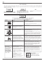
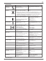
SAFETY PRECAUTIONS
This manual contains information that is important for you to know and understand. This information relates to USER SAFETY and
PREVENTING EQUIPMENT PROBLEMS. To help you recognize this information, we use the following symbols. Please pay particular
attention to these sections.
Important safety information - A hazard
that may cause serious injury or loss of life.
The following hazards may occur during the normal use of this equipment.
Please read the following chart before using this equipment.
Fire
Solvent Spray
Inhaling Toxic Substances
Explosion Hazard -
Incompatible Materials
General Safety
Cumulative Trauma
Disorders ("CTD's")
CTD's, or musculoskeletal
disorders, involve damage
to the hands, wrists,
elbows, shoulders, neck,
and back. Carpal tunnel
syndrome and tendinitis
(such as tennis elbow or
rotator cuff syndrome) are
examples of CTD's.
Solvent and coatings can be highly
flammable or combustible especially when
sprayed.
During use and while cleaning and flushing,
solvents can be forcefully expelled from
fluid and air passages. Some solvents can
cause eye injury.
Certain materials may be harmful if inhaled,
or if there is contact with the skin.
Halogenated hydrocarbon solvents - for
example; methylene chloride and 1,1,1,
- Trichloroethane are not chemically
compatible with the aluminum that might
be used in many system components. The
chemical reaction caused by these solvents
reacting with aluminum can become violent
and lead to an equipment explosion.
Improper operation or maintenance of
equipment.
Use of hand tools may cause cumulative
trauma disorders ("CTD's").
CTD's, when using hand tools, tend to affect
the upper extremities. Factors which may
increase the risk of developing a CTD include:
1. High frequency of the activity.
2. Excessive force, such as gripping,
pinching, or pressing with the hands and
fingers.
3. Extreme or awkward finger, wrist, or arm
positions.
4. Excessive duration of the activity.
5. Tool vibration.
6. Repeated pressure on a body part.
7. Working in cold temperatures.
CTD's can also be caused by such activities
as sewing, golf, tennis, and bowling, to
name a few.
Adequate exhaust must be provided to keep air free of
accumulations of flammable vapors.
Smoking must never be allowed in the spray area.
Fire extinguishing equipment must be present in the spray area.
Wear eye protection.
Follow the requirements of the Safety Data Sheet supplied by your
coating material manufacturer.
Adequate exhaust must be provided to keep the air free of
accumulations of toxic materials.
Use a mask or respirator whenever there is a chance of inhaling
sprayed materials. The mask must be compatible with the material
being sprayed and its concentration. Equipment must be as pre-
scribed by an industrial hygienist or safety expert, and be NIOSH
approved.
Due to the aluminum passageways in these guns, they must not be
used with these solvents. Aluminum is also widely used in other
spray application equipment – such as material pumps, regulators,
valves and cups. Check all equipment items before use and make
sure they can also be used safely with these solvents. Read the label
or data sheet for the material you intend to spray. If in doubt as to
whether or not a coating or cleaning material is compatible, contact
your material supplier.
Operators should be given adequate training in the safe use
and maintenance of the equipment (in accordance with the
requirements of NFPA-33, Chapter 15). Users must comply with
all local and national codes of practice and insurance company
requirements governing ventilation, fire precautions, operation,
maintenance, and housekeeping. These are OSHA Sections
1910.94 and 1910.107 and NFPA-33.
Pain, tingling, or numbness in the shoulder, forearm, wrist,
hands, or fingers, especially during the night, may be early
symptoms of a CTD. Do not ignore them. Should you experience
any such symptoms, see a physician immediately. Other early
symptoms may include vague discomfort in the hand, loss of
manual dexterity, and nonspecific pain in the arm. Ignoring early
symptoms and continued repetitive use of the arm, wrist, and
hand can lead to serious disability. Risk is reduced by avoiding or
lessening factors 1-7.
HAZARD CAUSE SAFEGUARDS
CA PROP
65
PROP 65 WARNING
WARNING: This product contains
chemicals known to the State of
California to cause cancer and birth
defects or other reproductive harm.
EN
SB-2-475-R1 (3/2018)2 / 8www.carlisleft.com

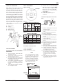
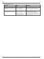
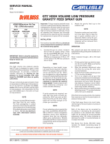
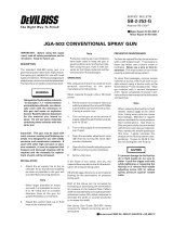
SPRAY GUN LUBRICATION
Daily, apply a drop of spray gun lube at
trigger bearing stud (28) and the stem
of air valve (20) where it enters air valve
assembly. The shank of fluid needle (11)
where it enters packing nut (9) should also
be oiled. Fluid needle packing (8) should be
lubricated periodically. Make sure baffle (6)
and retaining ring (3) threads are clean and
free of foreign matter. Before assembling
retaining ring to baffle, clean the threads
thoroughly, then add two drops of spray
gun lube to threads. Fluid needle spring (14)
and air valve spring (19) should be coated
with a very light grease, making sure that
any excess grease will not clog the air pas-
sages. For best results, lubricate the points
indicated, daily.
A. Trigger Points
B. Packing
C. Adjusting Knobs
D. Baffle Threads
E. Air Valve Cartridge
PARTS REPLACEMENT
FLUID INLET GASKET (32) REPLACEMENT
INSTUCTIONS
1. Remove fluid inlet adapter (34) with
appropriate wrench.
2. Clean thread sealant from gun body
inlet threads and seal area.
3. Place gasket (32) squarely onto the fluid
inlet adapter and push it down until it
is flat against the shoulder.
4. Use medium strength thread sealant
(i.e. Devcon 2242 blue, or equal) on
threads before installing fluid inlet
adapter.
5. Torque fluid inlet adapter to 20-25 ft.
lbs. and tighten locknut.
PARTS REPLACEMENT
Figure 1 Air Cap
A
C
D
B
E
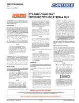
4. Assemble seal to baffle with angled
side up as shown in diagram. NOTE:
The seal should be a tight fit on the
baffle. If it is a loose fit on the baffle,
assure that it is assembled with the
angled side up.
5. Install baffle on gun.
6. Install fluid tip (5) and tighten to
15-20 ft-lbs.
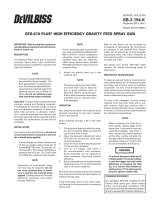
JGA-4035 Packing Replacement Instruc-
tions
1. Remove adjusting knob and needle
spring from gun.
2. Partially withdraw needle from gun
body.
3. Loosen packing nut and remove.
4. Remove old packing.
5. Assemble packing nut to needle.
6. Assemble packing in order shown to
needle.
7. Insert needle all the way into gun
body seating in tip.
8. Install needle spring and adjusting
knob.
9. Thread packing nut into gun body.
10. Tighten packing nut in equal incre-
ments - no more than
1/6 turn at a time.
11. After each adjustment, pull needle
open and observe needle closure.
12. If needle snaps shut, continue ad-
justing nut until there is evidence of
needle bind or slow closing.
13. Back off packing nut 1/12 turn to
the point where needle snaps shut.
Packing nut must remain tight
enough to prevent loosening by
hand.
14. Pull needle several times to verify
needle snaps shut and check pack-
ing nut for looseness.
Packing
(3 pieces)
Packing
Nut
Needle
Gun Body
GTI-33 Baffle Seal Replacement
1. Remove Fluid Tip (5).
2. Remove Baffle (6).
3. Remove Seal (7) from baffle.
NOTE
The seal is designed to be a tight
fit on the baffle. The seal should
be able to be removed using your
fingers. If you are unable to re-
move the seal using your fingers,
insert a small screwdriver between
the outer lip and the back of the
baffle and pry the seal off.
ANGLED SIDE
THICK SIDE
SEAL
BAFFLE
Air Cap No.
DeVilbiss
XXX
Pry here if
necessary
Chart 1
No. on
Air
Cap
Order
AV-440-410
AV-440-414
@60
psi
@50
psi
@40
psi
@30
psi
Type of
Fluid
Delivery
S=
Suction
P=
Pressure
S, P
P
410
414
Air Cap
With
Ring
(Ref. No. 4)
Air Flow (CFM)
9 13
14
11
16.5
19
Air Caps, Air Flows and Applications
Chart 2
Fluid Tips and Needles
Suction Feed Pressure Feed
Tip Size Fluid Fluid Fluid
Tip Needle Needle
In. mm (#5) (#11) (#11)
0.039 1.0 AV-213-10 NR GTI-449-12
0.047 1.2 AV-213-12 NR GTI-449-12
0.055 1.4 AV-213-14 GTI-413 GTI-449-12
0.063 1.6 AV-213-16 GTI-413 NR
0.070 1.8 AV-213-18 GTI-413 NR
NR = Not Recommended
EN
SB-2-475-R1 (3/2018) 3 / 8 www.carlisleft.com

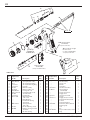
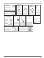
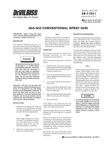
PARTS LIST
Ind.
Ref. Replacement Parts
No. Part No. Description Req.
1 --- Air Cap 1
2 JGA-156-K10 Spring Clip (Kit of 10) 1
3 GTI-3 Air Cap Retaining Ring 1
4 See Chart 1 Air Cap & Retaining Ring 1
5 See Chart 2 Fluid Tip 1
6 GTI-425 Baffle Assembly 1
•7 GTI-33-K5 Baffle Seal (Kit of 5) 1
•8 JGA-4035-K5 Packing (Kit of 5) 1
9 34411-122-K10 Packing Nut (Kit of 10) 1
10 GTI-405 Spreader Valve 1
11 See Chart 2 Fluid Needle 1
•12 JGS-72-K10 Gasket Kit (PTFE) 2
(Kit of 10)
13 --- Body Bushing 1
•14 --- Fluid Needle Spring 1
•15 --- Spring Pad 1
16 MBD-19-K10 Spring and Pad 1
(Kit of 10)
17 GTI-414 Needle Adjusting Screw 1
18 KK-5059 Bushing, Spring, Pad and 1
Knob Kit
•19 --- Air Valve Spring 1
Ind.
Ref. Replacement Parts
No. Part No. Description Req.
•20 --- Air Valve 1
21 --- Air Valve Body 1
•22 --- U-Cup Seal 1
•23 --- Washer 1
•24 --- Snap Ring 1
25 JGS-449-1 Air Valve Assembly 1
26 P-MB-51 Air Inlet Nipple 1
1/4" NPS(M)
27 --- Trigger Stud Screw 1
28 --- Trigger Stud 1
29 JGS-478 Stud and Screw Kit 1
30 --- Trigger 1
31 JGS-477-1 Trigger, Stud, Screw Kit 1
•32 --- Fluid Inlet Gasket (PTFE) 1
33 --- Locknut 1
34 --- Fluid Inlet Adapter 1
35 JGA-4042 Fluid Inlet, Gasket, Nut Kit 1
•36 --- Retaining Clip 1
•37 --- Seal 1
•38 --- Pin 1
39 GTI-428-K5 Clip, Seal & Pin Kit (5 each) 1
40 --- Plug 1
• KK-5058-2 Gun Repair Kit includes a quantity of necessary parts.
6
4
2
5
8
24
3
▲ 26 Air Inlet Nipple
1/4" NPS(M)
(torque to 15 ft.-lbs.)
16
17
14
9
11
10
▲ 34
32
Fluid Tip
(Torque to
15-20 ft.-lbs.)
33
1
15
12
13
18
23
22
21
20
19
12
25
▲ Use medium strength
thread sealant
(i.e. Devcon #2242 Blue,
or equal) on threads.
35
Fluid Inlet Nipple
3/8" NPS(M)
(torque to 20-25 ft.-lbs.)
7
29
31
28
27
30
40
36 37 38
39
EN
SB-2-475-R1 (3/2018)4 / 8www.carlisleft.com

Balance air pressure and fluid flow.
Increase spray pattern width with spreader
adjustment valve.
Thin or lower fluid flow.
Adjust.
Increase pressure.
Thin to proper consistency.
Reduce at transformer or gun.
Increase fluid flow (increases gun handling
speed).
Adjust.
Tighten or replace.
Install per directions.
Refill.
Hold more upright.
Backflush with solvent.
Lubricate or tighten.
Clean or replace.
Tighten.
Check air supply and air lines, blow out gun
air passages.
Open fluid needle adjusting screw.
Thin material and/or change to larger tip size,
or pressure feed.
Increase fluid pressure at tank.
Back fluid adjusting screw out to first thread,
or change to larger tip size, or increase fluid
pressure at tank.
Increase air pressure and rebalance gun.
Reduce pressure.
Adjust to proper distance.
Move at moderate pace, parallel to work
surface.
Remix properly.
Reduce pressure.
Reduce air pressure.
Adjust to proper distance.
Slow down.
Adjust.
Tighten, do not bind needle.
Replace or lubricate.
Adjust.
Lubricate.
Replace tip and needle.
Clean.
Replace.
Replace.
Adjust gun or reduce fluid flow.
Mix properly or apply light coats.
Hold gun at right angle to work and adapt to
proper gun technique.
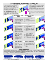
Heavy top or
bottom pattern
Heavy right or left
side pattern
Heavy center pattern
Split spray pattern
Jerky or fluttering spray
Unable to get round spray
Will not spray
Starved spray pattern
Excessive overspray
Excessive fog
Dry spray
Fluid leaking from packing nut
Fluid leaking or dripping from
front of gun
Runs and sags
TROUBLESHOOTING
Horn holes plugged.
Obstruction on top or bottom of fluid tip.
Cap and/or tip seat dirty.
Clean. Ream with non-metallic point.
Clean.
Clean.
Clean. Ream with non-metallic point.
Clean.
Fluid flow too high for atomization air.
Material flow exceeds air cap's capacity.
Spreader adjustment valve set too low.
Atomizing pressure too low.
Material too thick.
Atomization air pressure too high.
Fluid flow too low.
Spreader adjusting valve set too high.
*Loose or damaged fluid tip/seat.
Baffle seal not installed correctly.
Material level too low.
Container tipped too far.
Obstruction in fluid passage.
Dry or loose fluid needle packing nut.
Spreader adjustment screw not seating
properly.
Air cap retaining ring loose.
No air pressure at gun.
Fluid needle adjusting screw not open enough.
Fluid too heavy for suction feed.
Fluid pressure too low.
Inadequate material flow.
Low atomization air pressure.
Too much atomization air pressure.
Gun too far from work surface.
Improper stroking (arcing, gun motion
too fast).
Too much or too fast-drying thinner.
Too much atomization air pressure.
Air pressure too high.
Gun tip too far from work surface.
Gun motion too fast.
Gun out of adjustment.
Packing nut loose.
Packing worn or dry.
Packing nut too tight.
Dry packing.
Fluid tip or needle worn or damaged.
Foreign matter in tip.
Fluid needle spring broken.
Wrong size needle or tip.
Too much material flow.
Material too thin.
Gun tilted on an angle, or gun motion
too slow.
Left or right side horn holes plugged.
Dirt on left or right side of fluid tip.
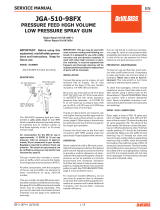
Remedies for the top-heavy, bottom-heavy, right-heavy, and left-heavy patterns:
1. Determine if the obstruction is on the air cap or the fluid tip. Do this by making a test
spray pattern. Then, rotate the cap one-half turn and spray another pattern. If the defect
is inverted, obstruction is on the air cap. Clean the air cap as previously instructed.
2. If the defect is not inverted, it is on the fluid tip. Check for a fine burr on the edge of the
fluid tip. Remove with #600 wet or dry sand paper.
3. Check for dried paint just inside the opening; remove by washing with solvent.
*Most common problem.
CONDITION CAUSE CORRECTION
EN
SB-2-475-R1 (3/2018) 5 / 8 www.carlisleft.com

TROUBLESHOOTING (continued)
CONDITION CAUSE CORRECTION
Paint bubbles in cup
Thin, sandy coarse finish drying before
it flows out
Thick, dimpled finish "orange peel"
Fluid tip not tight.
Gun too far from surface.
Too much air pressure.
Improper thinner being used.
Gun too close to surface.
Air pressure too low.
Improper thinner being used.
Material not properly mixed.
Surface rough, oily, dirty.
Tighten tip to 15-20 ft.-lbs.
Check distance. Normally approx. 6-8".
Reduce air pressure and check spray pattern.
Follow paint manufacturer's mixing instructions.
Check distance. Normally approx. 6-8".
Too much material coarsely atomized.
Increase air pressure or reduce fluid flow.
Follow paint manufacturer's mixing instructions.
Follow paint manufacturer's mixing instructions.
Properly clean and prepare.
EN
SB-2-475-R1 (3/2018)6 / 8www.carlisleft.com

HAV-500 OR
HAV-511
Adjusting Valve
(HAV-511 SHOWN)
HAV-500 does not have
pressure gage. Use to
control air usage at gun.
Spray Gun
Lube
SSL-10
(2 oz. bottle)
Compatible with all
paint materials; con-
tains no silicone or
petroleum distillates
to contaminate paint.
SDS Sheet available
upon request.
ACCESSORIES
TGC-545 Aluminum
Drip Free Suction Cups
Cups have a unique, two
position valve which permits
selection of either a drip free or
conventional open vent mode.
Automotive Quick Connects
For HVLP Guns (Air)
High Flow Type.
HC-4720 Coupler
1/4" NPT(F)
HC-1166 Stem
1/4" NPT(M)
HC-4419 Stem
1/4" NPT(F)
HC-4719 Coupler
1/4" NPT(M) /
NPS(M)
HARG-510
Air Regulator
Use to maintain nearly
constant outlet pres-
sure despite changes
in inlet pressure and
downstream flow.
KK-5060 Air Cap
Cleaning Kit
Consists of: 2
brushes, 1 wire
pick. Helps keep air
cap clean and per-
forming properly.
192218 Scrubs
®
Hand Cleaner Towels
Scrubs
®
are a pre-
moistened hand
cleaner towel for
painters, body men
and mechanics that
go where you go and
no water is needed.
HAF-507 Whirlwind™
In-Line Air Filter
Removes water, oil, and
debris from the air line.
Joins any single piece
DeVilbiss air cap with
latest version retaining
ring. Helps prevent part
loss and provides easier
assembly.
JGA-156-K10
Spring Clips
Contains all necessary tip,
hose and nut sizes used on
or with gun.
WR-103 Wrench
Contains six precision tools
designed to effectively clean
all DeVilbiss, Binks, Finishline
and other brand spray guns.
192212 Professional
Spray Gun Cleaning Kit
GTI-415
Air Adjusting Valve
Installs into gun to
enable user to control
and reduce air usage
at the gun. Replaces
JGA-132 plug.
NIOSH-Certified (TC-84A-1623)
for respiratory protection in
atmospheres not immediately
dangerous to life.
Twin Cartridge,
Paint Spray Respirator
40-128
EN
SB-2-475-R1 (3/2018) 7 / 8 www.carlisleft.com

EN
SB-2-475-R1 (3/2018)8 / 8www.carlisleft.com
WARRANTY POLICY
This product is covered by Carlisle Fluid Technologies’ materials and workmanship limited warranty.
The use of any parts or accessories, from a source other than Carlisle Fluid Technologies,
will void all warranties. Failure to reasonably follow any maintenance guidance provided
may invalidate any warranty.
For specic warranty information please contact Carlisle Fluid Technologies.
For technical assistance or to locate an authorized distributor,
contact one of our international sales and customer support locations.
Region Industrial/Automotive Automotive Renishing
Americas
Tel: 1-800-992-4657 Tel: 1-800-445-3988
Fax: 1-888-246-5732 Fax: 1-800-445-6643
Europe, Africa,
Middle East, India
Tel: +44 (0)1202 571 111
Fax: +44 (0)1202 573 488
China
Tel: +8621-3373 0108
Fax: +8621-3373 0308
Japan
Tel: +81 45 785 6421
Fax: +81 45 785 6517
Australia
Tel: +61 (0) 2 8525 7555
Fax: +61 (0) 2 8525 7575
Carlisle Fluid Technologies is a global leader in innovative nishing technologies.
Carlisle Fluid Technologies reserves the right to modify equipment specications without prior notice.
DeVilbiss
®
, Ransburg
®
, ms
®
, BGK
®
, and Binks
®
are registered trademarks of Carlisle Fluid Technologies, Inc.
©2018 Carlisle Fluid Technologies, Inc.
All rights reserved.
For the latest information about our products, visit www.carlisleft.com
-
 1
1
-
 2
2
-
 3
3
-
 4
4
-
 5
5
-
 6
6
-
 7
7
-
 8
8


DeVilbiss PLUS® Pressure Feed User manual
- Category
- Paint Sprayer
- Type
- User manual
- This manual is also suitable for
Ask a question and I''ll find the answer in the document
Finding information in a document is now easier with AI
Related papers
-
 DeVilbiss GTi® Suction Feed User manual
-
 DeVilbiss GTi® Gravity User manual
-
 DeVilbiss PLUS® Gravity User manual
-
 DeVilbiss GFG-670 PLUS Service Bulletin
-
 DeVilbiss JGA® Pressure Feed User manual
-
 DeVilbiss GTi® Pressure Feed User manual
-
 DeVilbiss JGA Maintenance And Troubleshooting Manual
-
 DeVilbiss JGA-510-98FX User manual
-
 DeVilbiss JGA-503 User manual
-
 DeVilbiss JGA-503 User manual


Other documents
-
Carlisle EXL-520S HVLP Suction Gun Owner's manual
-
-
-
Husky H4910DSG User manual
-
 Binks Cups & Accessories User manual
-
-
Husky H4840GHVSG User manual
-
 Binks Air Regulators User manual
-
 Binks Trophy Series Owner's manual
-
 ATD Tools ATD-16813 User manual


