— Do not store or use gasoline or other flammable vapors and
liquids in the vicinity of this or any other appliance.
— WHAT TO DO IF YOU SMELL GAS
• Do not try to light any appliance.
• Do not touch any electrical switch; do not use any phone in
your building.
• Immediately call your gas supplier from a neighbor’s phone.
Follow the gas supplier’s instructions.
• If you cannot reach your gas supplier, call the fire
department.
— Installation and service must be performed by a qualified
installer, service agency or the gas supplier.
WARNING: If the information in these instructions are not
followed exactly, a fire or explosion may result causing
property damage, personal injury or loss of life.
Owner’s Operation and Installation Manual for the
RHFE-750ETR
Direct Vent Fireplace
INSTALLER: Leave this manual with the appliance.
CONSUMER: Retain this manual for future reference.
Table of Contents .......... 2
Safety Information.......... 2
Operating Instructions.... 6
Care and Maintenance... 11
Fault Codes ................... 14
Installation Instructions .. 15
Consumer Support......... 36

2 Rinnai Corporation RHFE-750ETR
Consumer Safety Information
Safety Definitions........................................ 2
Safety Behaviors and Practices.................. 3
Safety Features........................................... 3
Specifications................................................. 4
Features ..................................................... 5
Dimensions................................................. 5
Flue Manifolds............................................. 5
Operating Instructions
Front Panel ................................................ 6
Remote Control Features ........................... 7
Remote Control Care..................................7
Sequence of Operations............................. 8
Basic Fireplace Operations
Turning ON and OFF............................. 8
Remote Control Operation..................... 8
Adjusting the Temperature .................... 9
Obstruction of Warm Air Discharge ....... 9
Lock Function ........................................ 9
Flame Function ...................................... 9
Auto Off Function................................... 9
Timers
Programming the Clock and Timers .... 10
Using the Timers.................................. 10
Using the Override............................... 10
Pre-heat ............................................... 10
Care and Maintenance
Maintenance ........................................ 11
Filters ................................................... 11
Visual Inspection of Flame .................. 11
Care of Exterior.................................... 12
Cleaning Combustion Chamber Glass 12
Troubleshooting........................................13
Fault Codes...............................................14
Installation Instructions
General Instructions..................................15
Clearances to Combustibles.....................15
Flue Terminal Clearances...................16, 17
Location ..............................................18, 19
Drilling Flue and Gas Supply Holes..........20
Flue Manifold Installation.................... 20, 21
Extension Kit Installation.....................22, 23
Connections........................................24, 25
Final Assembly
Install the Logs..................................... 26
Open the Air Guide Vanes................... 27
Install the Front Panel.......................... 27
Operating Instructions...............................28
Wiring and Schematic Diagram................29
Parts List..............................................30-36
Consumer Support
................................. 36, 37
This appliance may be installed in an aftermarket, permanently located, manufactured home
(USA only) or mobile home, where not prohibited by local codes.
This appliance is only for use with the type of gas indicated on the rating plate. This
appliance is not convertible for use with other gases, unless a certified kit is used.
Table of Contents
Consumer Safety Information
Safety Definitions
This is the safety alert symbol. This symbol alerts you to potential hazards that can kill or hurt you and
others.
Indicates an imminently hazardous situation which, if not avoided, will result in death or
serious injury.
Indicates a potentially hazardous situation which, if not avoided, could result in death or
serious injury.
Indicates a potentially hazardous situation which, if not avoided, could result in minor or
moderate injury. It may also be used to alert against unsafe practices.
CAUTION
WARNING
DANGER

Rinnai Corporation RHFE-750ETR 3
Safety Behavior and Practices
Safety Features
• Overheat: The appliance will automatically shut
down when the appliance exceeds a predetermined
temperature.
• Flame Failure: The appliance will automatically
shut down if the burner flame is extinguished.
• Power Failure: The appliance will cut off the gas if
it loses electrical power.
• Power Surge Fuse: A glass fuse power supply
harness protects against overcurrent. If the fuse
blows then all indicator lamps will be off.
• Spark Detector: The appliance automatically
shuts down if there is an abnormal spark at ignition.
• Keep the area around the appliance clear and free
from combustible materials, gasoline, and other
flammable vapors and liquids.
• Do not use this appliance if any part has been
under water. Immediately call a qualified service
technician to inspect the appliance and to replace
any part of the control system and any gas control
which has been under water.
• Do not operate appliance with the glass front
removed, cracked, or broken. Replacement of the
glass should be performed by a licensed or
qualified service technician.
• Broken or damaged components should be
removed or repaired by a licensed or qualified
service technician.
• Never store liquid propane containers indoors.
WARNING
• Do not block the warm air discharge. Do not allow
anyone to sleep directly in front of the appliance.
• Due to high temperatures, the appliance should be
located out of traffic and away from furniture and
draperies.
• Children and adults should be alerted to the
hazards of high surface temperature and should
stay away to avoid burns or clothing ignition. Hand
or body contact with the warm air discharge louvers
and glass must be avoided.
• Young children should be carefully supervised
when they are in the same room as the appliance.
• Clothing or other flammable material should not be
placed on or near the appliance.
• Do not insert items into the louvers.
• Do not spray aerosols near the appliance while it is
operating. Most aerosols contain butane gas which
is flammable.
• Do not place items on or against the appliance. If
there is a power failure while the appliance is ON
then the overheat vent on top of the panel may
open to release internal heat. An item placed on
top of the appliance could prevent the overheat
vent from opening resulting in damage to the
appliance.
• Any safety filter or guard removed for servicing
must be replaced prior to operating the appliance.
CAUTION

4 Rinnai Corporation RHFE-750ETR
Application Inbuilt only; for residential installation, commercial setting, or manufactured
home;
not designed for installation in a solid-fuel burning fireplace
General Description Inbuilt convector, glass and steel fronted, ceramic log space heater with
forced convection and power flue system
Operation Push button electronic / remote control
Gas Connection Flex line is 3/8 inch flare nut;
ball valve is 1/2 inch female x 3/8 inch flare
Gas Control Electronic
Burners Flame burners
Temperature Control Electronic thermostat
Logs Ceramic
Ignition System Electronic spark ignition
Flue System The flue must be terminated to atmosphere. Only flue components listed with
the appliance’s certification can be used. Warranty will be voided if non-listed
components are installed.
Fan 3 speed
Weight 154.3 lb (70 kg)
Electrical Connection AC 120V, 60 Hz
Specifications
Rinnai is continually updating and improving products. Therefore, specifications are subject to change without
prior notice.
Natural Gas Propane Gas
Minimum supply gas pressure 4.3 in (109 mm) W.C. 9.8 in (249 mm) W.C.
Maximum supply gas pressure 10.5 in (267 mm) W.C. 13.0 in (330 mm) W.C.
Manifold test pressure Factory Set Factory Set
BTU/hour input Natural Gas: Low - 10000 BTU/h; High - 29000 BTU/h
Propane: Low - 10000 BTU/h; High - 28000 BTU/h
BTU/hour output Natural Gas: Low - 7850 BTU/h; High - 21900 BTU/h
Propane: Low - 8050 BTU/h; High - 21840 BTU/h

Rinnai Corporation RHFE-750ETR 5
Features
• Direct Vent: Intake air is taken from the outside
and the combustion products are exhausted to the
outside. Therefore the furnace has no effect on the
quality of the indoor air.
• Push Button Ignition: Only one push of the
STANDBY/ON switch is all that is required to
operate the heater.
• Lock: The buttons on the remote control can be
locked to prevent any unintended operation.
• Dual Timer: The appliance can be programmed to
operate at two separate periods during the day.
• Pre-heat: The appliance will turn on before the
programmed ON time and begin raising the room
temperature to that of the programmed temperature
by the ON time.
• Memory: The computer memory records preset
temperatures, timer programming, and, operational
modes.
• Remote Control: The appliance has a fully
functioning cordless remote control.
• Auto-Off Function: You have the option of having
the flame display remain on or off once the room
temperature reaches the temperature setting.
See the installation instructions for the parts list of the
vent kit.
The “A” Vent Kit is included with the appliance.
The following flue manifold sizes are available:
Name Kit No. fits walls
A Vent Kit FOT-203 4 1/3 - 9 1/2 inch (110 - 240 mm)
B Vent Kit FOT-204 9 1/2 - 15 3/4 inch (240 - 400 mm)
Flue Manifolds
35 7/16 (900)
2 15/16 (71)
27 9/16 (700)
10 13/16 (274)
23 5/8 (600)
B
B
14 1/2 (369)
25 13/16 (655)
26 3/4 (679)
17 13/16 (453)
3 5/16 (84)
33 3/16 (842)
2 1/4 (57)
21 5/16 - 23 5/16 (542 - 592)
15 3/4 (400)
GAS CONNECTION
14 7/8 (378)
FLUE CONNECTION
4 15/16 (126)
33 3/16 (842)
Dimensions

6 Rinnai Corporation RHFE-750ETR
Operating Instructions
Front Panel
Description Part Number
Flat Metal - Black Front R2700
Flat Metal - Stainless Steel Front R2701
Radius (curved) Glass - Silver Front R2702
Radius (curved) Glass - Black Front R2703
Front Panel Models
Front Panel
(features are the same for flat and curved models)
TIMER INDICATOR
ON/OFF BUTTON
OPERATION INDICATOR
FAULT CODE DISPLAY
CONTROL PANEL
OVERHEAT
DISCHARGE VENT
TEMPERED GLASS IN THE
FRONT PANEL
CERAMIC GLASS PANEL AT
THE COMBUSTION CHAMBER
ROOM AIR RETURN
LOG SET
LOUVER, WARM
AIR DISCHARGE
REMOTE CONTROL
RECEIVER WINDOW
BLOCKAGE INDICATOR
for FILTERS (flashes red)
for WARM AIR DISCHARGE
(glows red)

Rinnai Corporation RHFE-750ETR 7
• Use two 1.5V AAA batteries.
• To replace batteries unscrew the battery
compartment cover located on the back of the
remote control counter clockwise. Ensure that
the correct polarity is observed. The polarity is
engraved into the battery compartment.
Replace the cover by turning clockwise until a
soft click is heard.
• To avoid damage from leaking batteries,
remove batteries if the remote control is not
going to be used for a long period.
• Some fluorescent lights may interfere with the
transmission of remote control signals.
• Avoid leaving the remote control in direct
sunlight.
• Do not place it close to the warm air discharge
louvers.
• Avoid dropping the remote control or getting it
wet.
Remote Control Features
Remote Control Care
STA N D BY
ON
Fl am e
Aut o
Off
Lock
Ti m er 2
Ti m er 1
Override
Ti m e
Se t
Te m p e r a t u r e
Lock
Cl o ck
AM
PM
Ti m er 1
Se t
Se t O N O FF
ON OFFTi m er 2 Set
Over ri de Aut o Off
Ti m e
Fl am e
DISPLAY
STANDBY / ON
BUTTON
Stops and operates the
heater remotely
FLAME BUTTON
Controls the flame level
AUTO OFF
AUTO OFF BUTTON
Turns the flame off when
the temperature setting is
reached.
LOCK BUTTON
Locks out control to
prevent unintended
operation
INFRA RED
EMITTER
TIMER 1 BUTTON
Sets timer program 1
TIMER 2 BUTTON
Sets timer program 2
TIME SET BUTTON
Sets the clock and timers
OVERRIDE BUTTON
Overrides timer
operation
UP and DOWN
BUTTONS
Changes temperature,
flame level, or time
O - I
0
1
Celsius (0)/
Fahrenheit (1)
switch

8 Rinnai Corporation RHFE-750ETR
Sequence of Operations
The combustion fan will run for several seconds
before ignition to purge the combustion chamber of
any gas.
If the front burner fails to ignite the appliance will turn
off and fault code 11 will be displayed. If the rear
burner fails to ignite the appliance will turn off and
make another attempt to ignite. If this second attempt
fails, the appliance will automatically turn off and fault
code 11 will be displayed. This may occur when using
the appliance for the first time or if it has not been
used for a while. Try operating the appliance again.
The appliance may make noises after ignition or
extinction of the flame. This is normal and is due to
the thermal expansion or contraction of its
components.
If the ON/OFF or the STANDBY/ON button is pressed
immediately after the flame has been extinguished,
the appliance will delay ignition for about 1 minute.
The normal ignition sequence is as follows:
1. When the ON/OFF or the STANDBY/ON button is
pressed the Operation Indicator LED will glow red
and the combustion fan will rotate to purge the
combustion chamber.
2. Electric ignitor operates.
3. Gas is allowed to flow to the pilot when a spark is
sensed.
4. When the pilot flame is established gas will flow to
the front burners and then to the rear burners.
5. When all burners are established the appliance
will automatically maintain the temperature
setting.
NOTE: The appliance will wait until the heat
exchanger is warmed up before discharging
air. This ensures that any discharge air will be
warm and not cold.
Basic Fireplace Operations
Turning ON and OFF
The Operation Indicator will glow red when the
appliance is ON.
The appliance will turn ON -
and attempt ignition:
• when you press the ON/
OFF button on the
appliance panel while the
appliance is OFF.
• when you press the STANDBY/ON button on the
remote control while the appliance is in
STANDBY.
• at the TIMER setting after you have activated the
TIMER and while the appliance is in STANDBY.
Pressing the STANDBY/ON button on the remote
control while the appliance is ON will put the
appliance in STANDBY mode, extinguishing
all flames and cause the Operation Indicator
to glow green.
Pressing the ON/OFF button while the
appliance is ON or in STANDBY will turn the
appliance OFF.
Remote Control Operation
The remote control emits an infrared (IR) signal and
must be aimed at the receiver located to the right of
the warm air discharge louvers. The normal
operating range is about 16 feet (4.9 m) with an angle
of about 40 degrees to the horizontal. This range will
vary depending on the position of the installation and
the strength of the remote control batteries.
Signal transmissions are confirmed by
• a brief illumination of the Transmission
Signal Indicator on the Remote Display
• a flash by the Remote Control Receiver to the
right of the louvers
• a beep from the appliance
The remote control transmits information whenever a
button is pressed except as follows:
• when the lock function is activated
• when setting the timers, timer information is
transmitted only when the “TIME SET” button is
pressed
STA N D BY
ON
Operation Indicator

Rinnai Corporation RHFE-750ETR 9
Adjusting the Temperature
Pressing the UP and DOWN buttons will change the
temperature setting by 2 degree (F)
increments. The display will show
“Temperature” and the new temperature as
confirmation.
The temperature can be set to:
• L (Low) - burner is on minimum
combustion
• 60° F - 80° F in two
degree increments
• H (High) - burner is
on maximum combustion
To use Celsius scale,
open the battery
compartment and move
the switch toward “0”.
The temperatures 16-26° C are available in one
degree increments. To return to Fahrenheit scale
move the switch toward “1”.
Te m p e r a t u r e
Lock
Cl o ck
PM
Ti m er 1
Se t
Se t ON OFF
ON OFFTi m er 2 Set
Override Aut o Off Flame
Flame Function
Press the FLAME button to control the flame
level. There are seven levels of flame
available.
The display will show the
word “Flame” and a series
of short bars (one for each
flame level).
Use the UP or DOWN
buttons to select the
desired flame level.
Pressing the FLAME
button again will allow the
appliance to control the
flame automatically.
If the room temperature reaches 104° F (40° C) while
the flame function is on then the appliance will turn off
automatically as a safety precaution.
The FLAME function is not available during TIMER
operation.
Te m p e r at u r e
Lock
Cl o ck
AM
PM
Ti m er 1
Se t
Se t ON OFF
ON OFFTi m er 2 Set
Override
Ti m e
Fl am e
Fl am e
Lock Function
Pressing the LOCK button will cause all
functions of the remote control to be locked
except for the STANDBY/ON button.
The remote control
display will show the word
“Lock” in the top left
corner.
To cancel the Lock
function press down and
hold the LOCK button for
3 seconds.
Te m p e r a t u r e
Lock
AM
PM
Override
Ti me
Lock
Auto Off Function
When the appliance is not in AUTO OFF mode and
the room temperature reaches the temperature
setting the appliance will reduce the gas
flow and maintain the flame on the lowest
flame level. The temperature may continue
to rise even on this low setting. If the
temperature reaches
104° F (40° C) then the
appliance will
automatically shut down
with fault code 16.
In AUTO OFF mode the
gas flow will be reduced
to pilot operation with no
visible flame when the
temperature setting is
reached. To enter this
mode press the AUTO OFF button. The words “Auto
Off” will be displayed above the time. To exit this
mode press the AUTO OFF again.
Whether this mode is on or off, the appliance will
attempt to maintain the temperature setting.
Te m p e r a t u r e
Lock
Cl o ck
AM
PM
Ti mer 1
Se t
Se t ON OFF
ON OFFTi mer 2 Set
Override Aut o Off
Ti me
Fl am e
Aut o
Off
Obstruction of Warm Air Discharge
Obstructing the louvers for the warm air discharge will
cause the appliance to operate inefficiently.
When an obstruction is detected the Blockage
Indicator LED above the Receiver Window will glow
red and combustion reduces to front burner, low
operation only.
To restore normal operation, remove the obstruction,
turn the appliance OFF and then ON.
Basic Fireplace Operations

10 Rinnai Corporation RHFE-750ETR
Timers
Programming the clock and timers
The clock must be set before the timers will operate.
The temperature setting during timer operation is the
temperature last used when the appliance was on.
During the steps below, if no button is pressed for 90
seconds then the screen will return to the current time
display.
1. Press the TIME SET button. The display
will show the words “Clock Set” and “AM
12:00” or the time.
2. Use the UP or DOWN buttons to set the
desired clock time.
NOTE: If you do not want to set the timers
now then press the TIME SET button five
more times to finish setting the clock.
3. Press the TIME SET button. “Timer 1
Set ON” and “AM 6:00” or
the last programmed time
will be displayed. Use the
UP or DOWN buttons to
set the desired on time.
When finished press the
TIME SET button.
4. “Timer 1 Set OFF” and
“AM 9:00” or the last
programmed time will be
displayed. Use the UP or
DOWN buttons to set the
desired off time. When
finished press the TIME
SET button.
5. To set Timer 2 repeat
steps 3 and 4. If finished
press the TIME SET
button two more times to
complete setting the clock
and Timer 1.
Pre-heat
The appliance may operate up to one hour before the
programmed ON time in order to allow the room to
reach the desired temperature by the programmed
ON time. The pre-heat time (how long before the
programmed ON time that the appliance will provide
heat) is determined by the difference between the
temperature setting and the room temperature one
hour before the programmed ON time.
Te m p e r a t u r e
Lock
Cl o ck
AM
Ti m er 1
Se t
Se t ON OFF
ON OFFTi m er 2 Set
OverrideAut o Off
Ti me
Fl am e
Te m p e r a t u r e
Lock
Cl o ck
AM
PM
Ti m er 1
Se t
Se t ON OFF
ON OFFTi m er 2 Set
OverrideAut o Off
Ti me
Fl am e
Ti m e
Se t
Using the Timers
Check the temperature setting before using the
timers.
One or both timers can be used. To allow
the appliance to operate during the pre-
programmed times press the TIMER 1 and/
or TIMER 2 button. The display will briefly
show the “on” and “off” times for each timer.
If the current time is outside of the
programmed times then the appliance will
Ti m er 1
Ti m er 2
Using the Override
This function is used to manually override
Timer programmed operation.
If the appliance is
operating in Timer mode
then pressing
OVERRIDE will turn the
it OFF and cause the
word “Override” to be
displayed for 10
seconds.
If the appliance is in
Timer mode but outside
of the programmed time
for operation then pressing OVERRIDE will turn the
appliance ON.
OVERRIDE does not change the programmed times.
Te m p e r at u r e
Lock
Cl o ck
AM
PM
Ti m er 1
Se t
Se t ON OFF
ON OFFTi m er 2 Set
Override Auto Off
Ti me
Fl am e
Override
go into standby mode and the Timer Indicator will
glow green.
To turn the timers off press the appropriate timer
button again. If the appliance was on, it will return to
standby mode and the Operation Indicator will glow
green.
The Timer Indicator will not display if both timers are
turned off.

Rinnai Corporation RHFE-750ETR 11
Care and Maintenance
Filters
This appliance has two filters which are behind the
louvers on either side of the heater. The louvers are
hinged to allow access to the filters.
Dirty filters reduce the air flow and the appliance’s
Maintenance
Repairs should be performed by a qualified service
technician. The appliance should be inspected
annually by a qualified service agency.
More frequent cleaning may be required due to
excessive lint from carpeting, bedding material, etc. It
is imperative that control compartments, burners, and
circulating air passage ways of the appliance be kept
clean.
When the appliance has cooled off, gain access by
removing the front panel, combustion chamber glass
panel, and ceramic logs. Refer to the Parts List and
the sections Cleaning Combustion Chamber Glass
and Final Assembly for disassembly / assembly
instructions. Vacuum, use pressurized air, and then
vacuum again to remove dust from the burners,
compartments, and convection fan.
Any filter or guard removed for servicing the
appliance must be replaced prior to operating the
appliance.
The vent should be inspected annually for blockages
or damage.
Motors are permanently lubricated and do not need
periodic lubrication. Keep fan and motor free of dust
and dirt by cleaning annually.
Verify proper operation after servicing.
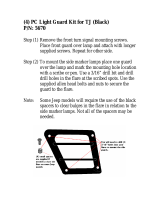
Visual Inspection of Flame
Check that the pilot and burner flames are operating
normally.
If flames appear either very short or very long and
streaky or are producing smoke or soot deposits then
there may be a problem with the appliance or gas
supply.
The appliance should not be used if you suspect
there is a problem. Call a qualified service technician
to inspect the appliance.
The burners are designed to produce two rows of
yellow flame but not smoke or soot.
NORMAL
ABNORMAL
ability to produce heat. The filters should be cleaned
once a week during the heating season. If the filters
become blocked the blockage indicator will flash red.
The filters should be cleaned whenever the blockage
indicator flashes red. If not cleaned the appliance
may turn off and display fault code 14 (overheat) on
the control panel display.
To clean the filters, the appliance should be OFF and
cool. Open the louver by pushing inward and
releasing. Slide the filter upwards until the bottom tab
clears the lower retaining slot. Then slide the filter
down and away to remove. Clean the filter using a
soft dry cloth or vacuum.

12 Rinnai Corporation RHFE-750ETR
WARNING
Do not clean glass when hot.
Do not clean glass with abrasive cleaners.
Care and Maintenance
Over time combustion products may leave a film on
the combustion chamber glass. Continued use of the
appliance may permanently stain the glass. If filming
occurs, this glass panel needs to be removed,
cleaned, and installed only by a qualified service
technician.

Rinnai Corporation RHFE-750ETR 13
Troubleshooting
No display on remote Replace the remote control batteries.
No ignition or no panel indications Ensure the appliance has power.
Press the control panel ON/OFF button.
Burners fail to ignite Air may need to be purged from the gas line. Several
ignition attempts may purge the gas line.
Turn on the gas supply.
Combustion stops during operation Remove any obstructions from the louvers.
Turn on the gas supply.
Smell of gas Follow the instructions in the warning block on the front of
this manual.
Remote control does not work Ensure the appliance has power.
Press the control panel ON/OFF button.
Press the LOCK button for 3 seconds if LOCK is displayed.
Press the STANDBY/ON button.
Warm air does not start immediately after burner
lights
The appliance will wait until the heat exchanger is warmed
up before discharging air. This ensures that any discharge
air will be warm and not cold.
Smoke or odors are produced when first operated This is caused by grease or oil on the heat exchanger or by
dust and should stop after a short time.
Clicking noises at ignition or shutdown Internal components are cooling (contracting) or heating up
(expanding) at different rates.
Clunking noise when the thermostat operates This is the sound of the solenoid gas valves opening and
closing to regulate the gas flow.
Convection fan continues to run after appliance is
turned OFF
The fan will continue to run to prevent internal components
from over heating.
Steam is discharged from the flue outside Steam discharge is normal.
Does not start while in STANDBY and the
temperature is below the setting
Timers must be turned off (or press OVERRIDE) for
manual operation.
Timers do not turn the appliance ON or OFF Timers may be turned off or incorrectly programmed.
Timer turns the appliance ON briefly and then the
appliance turns OFF before the OFF time setting.
The room temperature may be higher than the temperature
setting.
Problem Possible Solutions or Explanation

14 Rinnai Corporation RHFE-750ETR
Fault Codes
If there is a malfunction the appliance may shut down as a safety precaution and display a fault code to assist in
diagnosing the problem. The fault code will flash in the Fault Code Display window and the Operation Indicator
will flash green.
Code Fault Remedy
11 Ignition failure
Confirm that the gas supply is turned on. Switch appliance to
STANDBY and then ON again. If ignition failure continues
then a Service call is required.
12 Incomplete combustion Service call
14 Filter blocked or Overheat
Clean filters
If overheating continues then a service call is required to
determine the cause.
Thermal fuse; a qualified service technician must replace the
fuse following the procedure below.
16 Room overheat
The temperature has reached 104° F (40° C). Turn the
appliance off or engage the AUTO OFF function to prevent the
display of flame. See AUTO OFF section.
31 Room temperature sensor faulty Service call
32 Overheat temperature sensor faulty Service call
53 Spark sensor faulty Service call
61 Fan motor faulty Service call
71 Solenoids faulty Service call
72 Flame detection circuit fault Service call
73 Communication fault Service call
99 Flue block Check around flue terminal for obstructions to air flow
The cause of the overheat condition needs to be
determined and remedied before replacing the
thermal fuse.
A qualified service technician needs to:
1. Disconnect the appliance from the power supply.
2. Remove the right hand side panel to allow access
to the gas control and main PCB.
3. Unplug the thermal fuse harness (including the
control plug for the POV on the gas control) and
unscrew thermal fuse.
4. Re-assemble with replacement thermal fuse.
PCB
POV
Thermal Fuse
Replacement of Thermal Fuse

Rinnai Corporation RHFE-750ETR 15
Installation Instructions
General Instructions
A qualified service technician should install the
appliance and inspect it before use.
The installation must conform with local codes or, in
the absence of local codes, with the National Fuel Gas
Code, ANSI Z223.1/NFPA 54, or the Natural Gas and
Propane Installation Code, CSA B149.1.
A manufactured home (USA only) must conform with
the Manufactured Home Construction and Safety
Standard, Title 24 CFR, Part 3280, or, when such a
standard is not applicable, the standard for
Manufactured Home Installations, ANSI/NCSBCS
A225.1, or the standard for Gas Equipped
Recreational Vehicles and Mobile Housing, CSA
Z240.4.
The appliance, when installed, must be electrically
grounded in accordance with local codes or, in the
absence of local codes, with the National Electrical
Code, ANSI/NFPA 70, or the Canadian Electrical
Code, CSA C22.1.
Two 1/8 in test plugs are provided for testing of
manifold differential pressure.
The appliance must not be connected to a chimney
flue serving a separate solid-fuel burning appliance.
The appliance and its appliance main gas valve must
be disconnected from the gas supply piping system
during any pressure testing of that system at test
pressures in excess of 1/2 psi (3.5 kPa).
The appliance must be isolated from the gas supply
piping system by closing its equipment shutoff valve
during any pressure testing of the gas supply piping
system at test pressures equal to or less than 1/2 psi
(3.5 kPa).
If the flooring is carpet, tile, or other combustible
material other than wood, then the appliance must be
installed on a metal or wood panel extending the full
width and depth of the appliance.
This appliance discharges a large volume of warm air
next to the floor. Any particles in the air such as
cigarette smoke could cause discoloration in carpet.
The warm air flow could discolor nylon carpets
containing dyes or vinyl surfaces. To prevent
discoloration of the floor covering place a mat under
the appliance which extends about 30 inches in front
of it.
Refer to the conversion manual for high altitude
installations.
WARNING
Do not use substitute materials.
Use only parts certified with the appliance.
The clearances to combustibles as stated on the
rating plate and as shown in the figures must be
followed. Also refer to the Safety Behaviors and
Practices section.
1"
2"
3"
3"
4"
5"
45°
Top Panel of Fireplace
4"
Wall
CLEARANCES FROM THE SIDES
combustible projections (ex. mantles)
3"
1"
2"
4"
6"
3"
5"
45°
4"
Top Front
Edge
Wall
CLEARANCES
FROM THE TOP
Clearances to Combustibles

16 Rinnai Corporation RHFE-750ETR
Flue Terminal Clearances
INSIDE
CORNER DETAI L
FIXED
CLOSED
OPERABLE
FIXED
CLOSED
OPERABLE
B
B
B
A
J
B
M
C
F
B
B
E
D
L
G
A
H
K
I
X
V
AIR SUPPLY INLET
VENT TERMINAL
AREA WHERE
TERMINAL IS NOT
PERMITTTED

Rinnai Corporation RHFE-750ETR 17
Ref
Description
Canadian Installations US Installations
A
Clearance above grade, veranda, porch,
deck, or balcony
12 inches (30 cm) 12 inches (30 cm)
B
Clearance to window or door that may be
opened
12 inches (30 cm) 9 inches (23 cm)
C Clearance to permanently closed window * *
D
Vertical clearance to ventilated soffit,
located above the terminal within a
horizontal distance of 2 feet (61 cm) from
the center line of the terminal
* *
E Clearance to unventilated soffit * *
F Clearance to outside corner * *
G Clearance to inside corner * *
H
Clearance to each side of center line
extended above meter/regulator assembly
3 feet (91 cm) within a
height 15 feet (4.57 m)
above the meter/
regulator assembly
*
I Clearance to service regulator vent outlet 3 feet (91 cm) *
J
Clearance to nonmechanical air supply
inlet to building or the combustion air inlet
to any other appliance
12 inches (30 cm) 9 inches (23 cm)
K
Clearance to a mechanical air supply inlet
6 feet (1.83 m)
3 feet (91 cm) above if
within 10 feet (3 m)
horizontally
L
Clearance above paved sidewalk or
paved driveway located on public property
7 feet (2.13 m) 1 *
M
Clearance under veranda, porch, deck, or
balcony
12 inches (30 cm) 2 *
Flue Terminal Clearances
1 A vent shall not
terminate directly above
a sidewalk or paved
driveway that is located
between two single
family dwellings and
serves both dwellings.
2 Permitted only if
veranda, porch, deck,
or balcony is fully open
on a minimum of two
sides beneath the floor.
* For clearances not
specified in ANSI
Z223.1/NFPA 54 or
CSA B149.1,
clearances are in
accordance with local
installation codes and
the requirements of the
gas supplier.

18 Rinnai Corporation RHFE-750ETR
Do not vent the exhaust into ‘natural draft’ flue pipes
or a chimney flue.
The enclosure must be within these limits:
The front panel extends below the surface on which
the appliance rests. Ensure that clearance is
maintained in order to install the front panel.
Width (w) 33.8 in (860 mm)
Height (h) 26.0 - 26.2 in (660-665 mm)
Depth (d) 15.0 - 16.9 in (380-430 mm)
Enclosure Dimensions
For installation in the corner of the room refer to the
diagram at the right and the table below for
dimensions. These dimensions are the minimum
required if using the minimum width, height, and
depth dimensions above.
Enclosure Dimensions in a Corner
x 63.8 in (1620 mm)
y 45.1 in (1146 mm)
z 31.9 in (810 mm)
Location
This appliance has a cool outer casing that allows it to
be installed in a recessed application consisting of
combustible materials such as wood and plaster.
The location needs to have a level surface that allows
the appliance to be rolled in or out of the enclosure.
If the surface is elevated and there is not enough
room for it to be rolled out then a base and joists may
be used as shown.
The appliance will have to be rolled out for
maintenance. After installation do not place any
permanent fixtures that would prevent pulling the
appliance out for access. To pull the appliance
completely out of the enclosure a minimum of 15
inches from the front panel would be needed.
w
d
h
x
y
z
JOIST JOIST
RIGHT
WHEEL
LEFT
WHEEL
28.3 in (720 mm)

Rinnai Corporation RHFE-750ETR 19
Location
Use the adjustment feet so that the appliance is level
and not tilted. They are initially installed immediately
behind the side louvers but can be moved forward for
better access in hearth or floor installations.
The hearth should not block the appliance.
Correct Floor
Level Installation
Particle Board, MDF, Plywood etc.
Wall Lining
Particle Board, MDF, Plywood etc.
Wall Lining
Particle Board, MDF, Plywood etc.
Wall Lining

20 Rinnai Corporation RHFE-750ETR
2. Assemble and Adjust the Sleeve Length
Measure wall thickness through previously drilled
3 1/2 inch (90 mm) hole.
The end of the sleeve should protrude 3/16 - 3/8
inch (5-10 mm) from the outside wall.
In the “A” vent kit there are 4 parts provided with
which to assemble the sleeve. Use the table to
determine which pieces to assemble.
In both the “A” and “B” vent kits, two parts are
threaded for additional adjustment.
Adjust the sleeve length to wall thickness plus
3/16 - 3/8 inch (5-10 mm).
Flue Manifold Installation
1. Disassemble the Flue Manifold
The flue consists of 3 parts:
• sleeve
• inside connection
• terminal
Disassemble the flue manifold by first pulling
out the inside connection. To remove the
outer terminal pull and release the two
internal ties and then pull out the outer
terminal.
Clearance to combustibles for the sleeve and
flanges is zero inches.
Drilling Flue and Gas Supply Holes
Check for water and gas pipes as well as electric
cables. Use the template supplied to mark the wall
locations for the flue manifold and the gas supply.
Drill the flue hole using a 3 1/2 inch (90 mm) drill.
For weatherboard walls, drill through the center of the
weatherboard from the outside first and then through
the plasterboard.
Inside Connection
Sleeve
Terminal
Sleeve Parts
a
b
c
For wall thickness plus 3/16 - 3/8 in (5-10 mm) Assemble these parts (“A” Vent Kit)
4 1/3 - 6 1/8 in (110 - 155 mm)
6 1/8 - 7 3/4 in (155 - 195 mm)
7 3/4 - 9 1/2 in (195 - 240 mm)
a
b
+
a
b
c
++
a
b
c
++
c
+
Page is loading ...
Page is loading ...
Page is loading ...
Page is loading ...
Page is loading ...
Page is loading ...
Page is loading ...
Page is loading ...
Page is loading ...
Page is loading ...
Page is loading ...
Page is loading ...
Page is loading ...
Page is loading ...
Page is loading ...
Page is loading ...
Page is loading ...
Page is loading ...
Page is loading ...
Page is loading ...
/