Page is loading ...

AWNINGS
SLIDE TOPPER™
REVISION E Form No. 3314719.000 08/19 | ©2019 Dometic Corporation
Hardware: 98000(LL).40(Y)(#)
Fabric Roller Tube Assembly: 98(X)0(Z)(YY).(LLL)(#)
EN
Slide Topper
Installation and Operation Manual ........2

2
EN
Contents Slide Topper
1 Explanation of Symbols and Safety
Instructions ............................ 2
1.1 Recognize Safety Information .............2
1.2 Understand Signal Words ................2
1.3 Supplemental Directives .................2
1.4 General Safety Messages ................3
2 General Information ..................... 3
2.1 Finding Tools and Materials ..............3
2.2 Identifying the Model ...................4
3 Pre-Installation ......................... 4
3.1 Extending the Slide-Out Room ............5
3.2 Identifying the Required Clearances .......5
3.3 Identifying the Bracket Configuration .......6
3.4 Using an Optional Mounting Bracket
Spacer ...............................7
3.5 Marking the Mounting Bracket Location ....7
3.6 Preparing the Hardware Assembly .........8
4 Installation ............................. 8
4.1 Installing the Awning Rail and the Fabric ....9
4.2 Installing the Mounting Brackets ..........10
4.3 Installing the Anti-Billow Stop ............ 11
4.4 Securing the Awning Fabric to the
Awning Rail ..........................12
5 Operation ............................. 13
6 Maintenance .......................... 13
6.1 Maintaining the Hardware ..............14
6.2 Maintaining the Fabric ..................14
7 Troubleshooting ....................... 14
8 Disposal .............................. 15
LIMITED ONE-YEAR WARRANTY ............. 15
Contents
Service Center & Dealer Locations
Visit: www.dometic.com
Read these instructions carefully. These instructions
MUST stay with this product.
1 Explanation of Symbols and
Safety Instructions
This manual has safety information and instructions to
help you eliminate or reduce the risk of accidents and
injuries.
1.1 Recognize Safety Information
This is the safety alert symbol. It is used to alert
you to potential physical injury hazards. Obey all
safety messages that follow this symbol to avoid
possible injury or death.
1.2 Understand Signal Words
A signal word will identify safety messages and property
damage messages, and also will indicate the degree or
level of hazard seriousness.
DANGER!
Indicates a hazardous situation that, if not avoided,
will result in death or serious injury.
WARNING
Indicates a hazardous situation that, if not avoided,
could result in death or serious injury.
CAUTION
Indicates a hazardous situation that, if not avoided,
could result in minor or moderate injury.
NOTICE: Used to address practices not related to
physical injury.
I
Indicates additional information that is not related
to physical injury.
1.3 Supplemental Directives
To reduce the risk of accidents and injuries, please
observe the following directives before proceeding to
install or operate this appliance:
• Read and follow all safety information and
instructions.
• Read and understand these instructions before
installing this product.

3
EN
Slide Topper General Information
• The installation must comply with all applicable local
or national codes, including the latest edition of the
following standards:
U.S.A.
– ANSI/NFPA70, National Electrical Code (NEC)
– ANSI/NFPA 1192, Recreational Vehicles Code
– ANSI Z21.57, Recreational Vehicles Code
Canada
– CSA C22.1, Parts l & ll, Canadian Electrical Code
– CSA Z240 RV Series, Recreational Vehicles
1.4 General Safety Messages
WARNING: FIRE, IMPACT, AND/OR CRUSH
HAZARD. Failure to obey the following
warnings could result in death or serious
injury:
• Use only Dometic replacement parts and
components that are specifically approved for use
with the appliance.
• Avoid improper installation of the Slide Topper.
Installation and maintenance must be done by a
qualified service person only.
• Do not modify this product in any way. Modification
can be extremely hazardous.
• Use care when diagnosing and/or adjusting
components on a powered unit.
• Keep sources of heat and fire (barbecue grills,
portable heaters, etc.) away from the Slide Topper.
• Do not allow children to play with this product or
with fixed controls (if applicable).
• Do not allow anyone (including children) with
reduced physical, sensory or mental capabilities,
or lack of experience and knowledge to use this
product, unless they have been given supervision or
instruction concerning the use of this product by a
person responsible for their safety.
• Never leave an open Slide Topper unattended. Keep
it stowed (closed) when snow, heavy rain, wind, and
severe weather conditions are expected.
CAUTION: PINCH HAZARD.
Maintain a horizontal distance of at least 16 in.
(407 mm) between the fully opened Slide Topper
and any permanent object. Failure to obey this
caution could result in minor or moderate injury.
I
Do not face the slide-out room or Slide Topper
toward permanent objects that my interfere with
the operation.
2 General Information
The images used in this document are for reference
purposes only. Components and component locations
may vary according to specific product models.
Measurements may vary ±0.38 in. (10 mm).
2.1 Finding Tools and Materials
Refer to the following tables for the included, required,
and optional hardware and kits available for the Slide
Topper.
Included Hardware Quantity
Le Hand Topper Arm with 15 in. (38 cm) or 18
in. (46 cm) Extension (Bar)
1
Right Hand Topper Arm with 15 in. (38 cm) or
18 in. (46 cm) Extension (Bar)
1
Cotter R-Pin 2
#10 - 12 x 1 in. Screw 12
#8 - 18 x 3/8 in. Screw 6
#6 - 20 x 7/16 in. Self-Drilling Screw 2
Included Anti-Billow Bracket Kit Quantity
Anit-Billow Stop 1
#10 - 16 x 3/4 in. Screw 2
Anit-Billow Bracket 1
Anit-Billow Spacer 1
#10 - 12 X 3/4 in. Screw 3
3/16 in. X 3/8 in. Oscar Rivet 2

4
EN
Pre-Installation Slide Topper
Required Topper
Bracket Set
1
Part Number Quantity
Topper Short (Wall)
Bracket with Hardware
98000(LL).401(#) 2
Topper Tall (Wall)
Bracket with Hardware
98000(LL).402(#) 2
1
A Topper bracket set (not included) is required. Choose the set that permits
the minimum clearances to be met for your specific application.
Slide Toppers that are 198 in. (503.0 cm) to 259 in.
(657.9 cm) require the following kits:
• A second anti-billow stop kit (one at each end cap)
• A second anti-billow bracket kit (one at each end cap)
• One (1) cradle kit for center support of the Fabric
Roller Tube Assembly (FRTA)
In addition to the above, it is recommended that Slide
Toppers that are 260 in. (660.4 cm) or wider install a
second cradle kit.
Optional Kits Part Number Quantity
Mounting Bracket Spacer Kit
0.75 in. (19 mm) thick
3107940.003 1
Mounting Bracket Spacer Kit
0.50 in. (13 mm) thick
3310066.000# 1
Anti-Billow Stop Kit 3109252.XXX# 1
Anti-Billow Bracket Kit 3107198.XXX# 1
Cradle Kit 3309526.XXX# 1
Optional Components Part Number Quantity
Awning Rail 3106774.XXX-# 1
Awning Rail 20 . (6.1 m)
(20 pack)
3106774.262-# 1
Oscar Rivet (10 pack) 113008P10 1
Oscar Rivet (100 pack) 113008P100 1
Recommended Tools
Drill Flat Screwdriver
3/16 in. (4.7 mm) Drill Bit 7/16 in. (11 mm) Drill Bit
Sealant File
Measuring Tape
2.2 Identifying the Model
This section describes the breakdown of the model
identification numbers.
Hardware
98000LL . 40Y #
Hardware Color
1 = Tall, 2 = Short
Extension (15, 18)
FRTA
98X 0Z YY . LLL #
Color
Length
Fabric Color
0 = No Rail Included, 1 = Rail Included
Number of Slats
Intended Use
This Slide Topper is designed and intended for use on a
recreational vehicle (hereinaer referred to as “RV”). Use
these instructions to ensure the correct installation and
function of the product.
The manufacturer accepts no liability for damage in the
following cases:
• Faulty assembly or connection
• Damage to the product resulting from mechanical
influences and excess voltage
• Alterations to the product without express permission
from the manufacturer
• Use for purposes other than those described in the
operating manual
Dometic Corporation reserves the right to modify
appearances and specifications without notice.
3 Pre-Installation
Use this section to mark the location of the mounting
brackets that were selected for the installation of the
Slide Topper and prepare the hardware for assembly.

5
EN
Slide Topper Pre-Installation
3.1 Extending the Slide-Out Room
q
w
1 RV Slide-Out Room Extension
q
Slide-Out Room Width
(including Flange)
w
Slide-Out Room
Maximum Extension
Begin by extending the slide-out room. The full extension
of the slide-out room must not exceed 42 in. (106.7 cm).
Refer to the Slide Topper Application Guide (located
on dometic.com) to determine the appropriate Slide
Topper width for the slide-out room application and
to select the fabric, mounting brackets, and optional
spacers needed for the installation of the Slide Topper.
3.2 Identifying the Required
Clearances
NOTICE: Employ as steep of a pitch as possible for the
awning fabric without exceeding the maximum distance
required between the awning rail and mounting bracket
(refer to Figure 2 and Figure 3). Exceeding the maximum
distance exposes the awning fabric to wind, causing the
fabric to billow or tear.
Use this section to confirm your Slide Topper clearance
measurements.
t
q
w
t
y
u
i
e
r
o
a
2 Tall Mounting Bracket Clearance
q
0.5 in. (1.3 cm) min. –
4 in. (10 cm) max.
y
Slide-Out Room
Flange
w
0.25 in. (0.6 cm) min.
u
Extension
e
Mounting Bracket
i
Mounting Bracket
r
Slide-Out Room Flange
o
Rotating Assembly
t
Awning Rail
a
0.5 in. (1.3 cm) min.
* Callout 10 represents the minimum clearance required
between the Slide Topper rotating assembly, all
obstructions on the RV slide-out room, and all
obstructions on the stationary wall.

6
EN
Pre-Installation Slide Topper
t
o
a
q
w
t
y
u
i
e
r
3 Short Mounting Bracket Clearance
q
0.5 in. (1.3 cm) min. –
4 in. (10 cm) max.
y
Slide-Out Room Flange
w
0.25 in. (0.6 cm) min.
u
Extension
e
Mounting Bracket
i
Mounting Bracket
r
Slide-Out Room
Flange
o
Rotating Assembly
t
Awning Rail
a
0.5 in. (1.3 cm) min.
* Callout 10 represents the minimum clearance required
between the Slide Topper rotating assembly, all
obstructions on the RV slide-out room, and all
obstructions on the stationary wall.
Confirm the identified clearances. In addition, the
Slide Topper must have a 0.5 in. (1.3 cm) minimum
clearance between the Slide Topper rotating assembly,
all obstructions on the RV slide-out room, and all
obstructions on the stationary wall. Optional bracket
spacers may be used to achieve this clearance.
3.3 Identifying the Bracket
Configuration
Use this section to identify the Slide Topper
configuration of your application.
I
If the slide-out room of the RV has extra large
flanges, mount the brackets directly onto the flange
only if it provides a solid structural support. Never
mount brackets on an unsupported area of the
flange or on the awning rail.
A B
X
Y
X
Y
C D
X
Y
X
Y
E F
X
Y
X
Y
G H
X
Y
X
Y

7
EN
Slide Topper Pre-Installation
Ref. Bracket Position
Extension
Position
Dimension
Specifications
(X) (Y)
A Tall Standard Standard 1.79 in.
(4.5 cm)
5.33 in.
(13.5 cm)
B Tall Standard Inverted 1.83 in.
(4.6 cm)
5.70 in.
(14.5 cm)
C Short Standard Standard 1.21 in.
(3.1 cm)
4.01 in.
(10 cm)
D Short Standard Inverted 1.21 in.
(3.1 cm)
4.38 in.
(11 cm)
E Tall Inverted Standard 1.02 in.
(2.6 cm)
2.91 in.
(7.4 cm)
F Tall Inverted Inverted 0.98 in.
(2.5 cm)
3.27 in.
(8.3 cm)
G Short Inverted Standard 1.21 in.
(3.1 cm)
4.26 in.
(11 cm)
H Short Inverted Inverted 1.21 in.
(3.1 cm)
4.63 in.
(12 cm)
3.4 Using an Optional Mounting
Bracket Spacer
When the RV slide-out room flange has special features
like a large curve, or the flange is recessed into the RV
wall, use a mounting bracket spacer (not included).
I
The mounting bracket spacer thickness may vary
depending on the spacer kit requirements.
q
q
r
w
e
4 Optional Mounting Bracket Spacer
q
0.5 in. or 0.75 in. (1.3 cm or
2.0 cm) Mounting Bracket
Spacer (size may vary)
e
RV Wall
w
Large Curve in Flange
r
Recessed Flange
3.5 Marking the Mounting Bracket
Location
Use this section to mark the location of the mounting
brackets that were selected for the installation of the
Slide Topper.
q
w
e
w
w
5 Mounting Brackets
q
Fabric Roller Tube
Assembly
e
Slide-Out Room
w
Mounting Bracket
1. Find a solid structure in the RV slide-out room wall for
support of the mounting brackets.
2. Mark the spacing for the mounting brackets. The
spacing should be centered on the RV slide-out room.

8
EN
Installation Slide Topper
q
w
e
6 Mounting Bracket Locations
q
Mounting Bracket
Below Flange
e
Incorrect Mounting
Bracket Location
w
Mounting Bracket
Directly on Flange
3. Verify the mounting location is flat and has solid
structural backing where the fasteners will penetrate
the surface.
4. Verify the mounting brackets are positioned at the
correct height in relation to the Slide Topper arms
and extension.
5. Mark the hole locations for the mounting brackets
using the mounting brackets as templates.
3.6 Preparing the Hardware
Assembly
Use this section to prepare the hardware for the
installation of the Slide Topper.
q
w
e
r
7 Rear View of Hardware Assembly
q
Torsion Rod
e
Cotter R-Pin
w
LH Arm
r
Extension
1. Carefully lay the FRTA onto a clean, well padded “V”
trough (or other well protected surface) to prevent
fabric damage.
2. Place the LH (le hand) arm onto the torsion rod.
3. Align the clip holes.
4. Install the cotter R-pin through the LH arm and into
the torsion rod until it securely snaps into place.
5. Repeat steps 2 – 4 for the other end.
I
Make sure the LH and RH (right hand) arms align
correctly with each other.
4 Installation
WARNING: FIRE OR ELECTRICAL SHOCK
HAZARD. Failure to obey these warnings
could result in death or serious injury.
• Make sure there are no obstacles like wires or pipes in
the way of the drill locations.
• Disconnect the 120 VAC power supply from the RV
before drilling or cutting into the RV.
• Disconnect the positive (+) 12 VDC terminal from the
supply battery before drilling or cutting into the RV.

9
EN
Slide Topper Installation
WARNING: EXPLOSION HAZARD.
Shut off the gas supply in the RV before drilling or
cutting into the RV. Failure to obey this warning
could result in death or serious injury.
WARNING: IMPACT OR CRUSH HAZARD.
Make sure the mounting surface of the RV is flat, has
a solid structural back where the fasteners penetrate
the surface, and will safely and securely support the
product. The product may become unstable and
could detach, bend, or collapse. Failure to obey
this warning could result in death or serious injury.
NOTICE: Review the following notices prior to
beginning installation:
• Always seal against weather and moisture where
components enter the RV’s walls, roof, or floor. If this
is ignored, water intrusion can occur.
• Before installing the awning fabric, make sure the
awning rail is parallel to the RV floor and is not
warped or curved. If the awning rail is not straight,
awning the awning fabric may wrinkle or stretch.
• At least one other person is required to help hold and
control the Slide Topper until the mounting brackets
are installed onto the RV and the FRTA, with the arms
and extensions, is installed on the mounting brackets.
Failure to control the Slide Topper at this point can
result in product damage.
• The cotter pins must be removed from the Slide
Topper end caps before operating the slide-out
room. Failure to remove the cotter pins before
operation can result in product damage.
This section provides the information needed to install
the Slide Topper.
4.1 Installing the Awning Rail and
the Fabric
Use the following steps for the installation of the awning
rail and the fabric.
1. Determine the awning rail location relative to the
mounting bracket and slide-out room flange.
2. Remove any flashing or drip shields that will interfere
with the Slide Topper.
I
The Slide Topper may be assembled and held in
place to check for interference.
3. Apply sealant to the back edge of the awning rail and
to the #8 – 18 x 1 in. screws.
4. Place the awning rail in the mounting location.
5. Tighten the screws through the awning rail and into a
solid surface to secure the awning rail.
I
Some models do not include the rail and screws.
If an awning rail and screws are needed, refer to
“Finding Tools and Materials” on page 3.
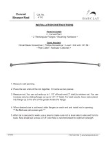
8 Widening the Awning Rail
6. Select the desired awning rail end in which the
awning fabric will be inserted.
7. Widen the end of the rail with a flat screwdriver and
file off any sharp edges.
q
w
9 Guiding the Awning Fabric Through the Awning Rail
q
Awning Fabric
w
Awning Rail
8. Unfurl the awning fabric one revolution to allow
enough room between the wall and the awning
hardware to guide the fabric into the awning rail.

10
EN
Installation Slide Topper
I
Unfurling the awning fabric more than one
revolution of fabric can cause issues with the awing
function.
9. With the slide-out room of the RV completely closed,
carefully li the Slide Topper to the installed awning
rail end above the top of the slide-out.
10. While one person guides the awning fabric (or
awning roller cover, if applicable) into the awning rail,
carefully slide the Slide Topper until the fabric is in the
desired position.
I
A stepladder may be necessary to guide the fabric.
4.2 Installing the Mounting Brackets
1. Drill a 3/16 in. (0.12 cm) [7/32 in. (0.56 cm) if you are
drilling into steel] hole approximately 1 in.
(2.5 cm) deep into the slide-out room on the marked
hole locations.
2. Apply sealant to the provided #10 - 12 x 1 in. screws.
3. Place the mounting brackets onto the marked
locations on the RV slide-out room.
4. Tighten the screws through the mounting bracket and
into the solid structure of the RV slide-out room.
I
If an optional spacer kit is needed, use the #10 x
1.75 in. screws provided with the kit. Use the 3/16
x 1 in. oscar rivets when installing the mounting
brackets onto laminated walls.
q
r
w
y
e
t
10 Securing the Mounting Bracket
q
Mounting Bracket
r
Extension Cap
w
#10 - 12 x 1 in. Screw
t
LH Arm
e
Extension
y
Slide-Out Room
5. Repeat steps 1 – 5 for the other mounting bracket.
Do not allow the mounting brackets to extend more
than half their length beyond the end of the extension
bar. At least 50% of the mounting bracket length must
be inserted into the extension.
6. Center the Slide Topper on the RV slide-out room.
w
r
q
e
11 Securing the Extension to the Mounting Bracket
q
Mounting Bracket
e
LH Arm
w
#8 – 18 x 3/8 in. Screw
r
Extension
7. Insert the provided #8 – 18 x 3/8 in. screws into the
mounting brackets.
8. Clamp the Slide Topper extensions onto the
mounting brackets.
w
e
q
12 Removing the Cotter Pin
q
Cotter Pin
e
LH Arm
w
End Cap

11
EN
Slide Topper Installation
WARNING: IMPACT OR PINCH HAZARD.
Do not remove the cotter pin from the torsion rod
until the awning fabric is attached to the awning
rail, the torsion rod is secured to the assembled
hardware, and the hardware is secured to the slide-
out room. Rapid casting spin off will occur. Spring
tension will attempt to spring the hardware and/
or the fabric roller tube quickly and unexpectedly.
Failure to obey this warning could result in death or
serious injury.
9. Remove and discard the cotter pin from the LH
torsion rod at the LH end cap.
Removing the cotter pin will release factory preset
tension. To facilitate removal, rotate the fabric roller
tube by pulling the bottom of the tube forward while
pulling on the cotter pin.
10. Repeat step 9 for the RH end.
4.3 Installing the Anti-Billow Stop
This section provides the information needed to install
the anti-billow stop.
q
w
e
w
q
t
e
r
r
90°
45°
Up
Wall
13 Installing and Positioning the Anti-Billow Stop
q
Anti-Billow Stop
Bumper
r
LH Arm
w
#10 Self-Drilling Screw
t
Anti-Billow Bracket
e
End Cap
1. Determine onto which end cap the anti-billow stop
will be installed.
I
Slide Toppers 198 in. (503 cm) or wider require an
anti-billow stop at both end caps and a cradle kit
for the center support. Refer to “Finding Tools and
Materials” on page 3.
2. Place the anti-billow stop onto the end cap with the
opening facing away from the awning rail.
3. Position the anti-billow stop with the bumper pointed
straight up.
4. Tape the anti-billow stop in place on the end cap.
I
If either screw hole in the anti-billow stop interferes
with the existing holes or openings in the end cap,
rotate the anti-billow stop no more than 30° from
the vertical position away from the RV wall.
q
w
5/16 in. 1/2 in. 3/4 in. 1 in. 1-1/2 in.
14 Configurations for the Anti-Billow Bracket and Spacer
q
Anti-Billow Bracket
w
Anti-Billow Spacer
5. Determine the required configuration of the anti-
billow bracket and the spacer (spacing from the RV
wall) to ensure the anti-billow stop will not rotate past
a 45° angle toward the RV wall.
The anti-billow bracket and anti-billow spacer can be
configured for a spacing range of 0.31 in. to 1.5 in.
(0.78 cm to 4 cm).
6. Using the correct spacing configuration, position the
anti-billow bracket and anti-billow spacer onto the RV
wall.

12
EN
Installation Slide Topper
q
e
t
w
r
15 Securing the Anti-Billow Bracket
q
Anti-Billow Bracket
r
Up (Resting Position)
w
Anti-Billow Spacer
t
#10 – 12 x 3/4 in.
Screw
e
Anti-Billow Stop
7. Tape the bracket and spacer in place.
8. Verify the anti-billow stop will clear the anti-
billow bracket as the slide-out room opens. Make
adjustments as necessary.
9. Place and tighten the provided #10 self drilling screws
through the anti-billow stop and into the end cap.
I
Do not move the anti-billow stop or scratch the end
cap while installing the screws.
10. Place and tighten the provided #10 – 12 x 3/4 in.
screws through the anti-billow bracket and into the
solid structure on the RV.
If installing the anti-billow bracket onto fiberglass, use the
proper oscar rivets (not provided) instead of the screws.
Refer to “Finding Tools and Materials” on page 3.
11. Remove the tape from the anti-billow stop, end cap,
and anti-billow bracket.
12. Repeat steps 1 – 11 for the second anti-billow stop (if
applicable) on the other end cap.
4.4 Securing the Awning Fabric to
the Awning Rail
1. Verify the cotter pins have been removed from the
end caps.
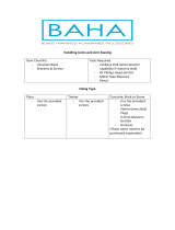
q
w
e
2 in.
16 Securing the Awning Fabric
q
Awning Rail
e
#6 x 7/16 in. Screw
w
Fabric Edge
2. Open and close the RV slide-out room four or
five times to allow natural self adjustment of the
awning fabric. Refer to the RV operators manual for
instructions on how to operate the RV slide-out room.
3. Verify the alignment of the awning fabric. If
the awning fabric is misaligned, adjust the arm
extensions:
a. Loosen the clamping screws.
b. Move the extension accordingly.
c. Retighten the screws.
d. Cycle the RV slide-out room again to check
proper alignment.

13
EN
Slide Topper Operation
4.4.1 Securing Slide Toppers With Metal
Slats
Use this section for securing the awning fabric to the
awning rail if the Slide Topper has metal slats.
e
q
w
17 Securing the Metal Slide Topper
q
Awning Rail
e
#6 x 7/16 in. Screw
w
Top Slat
Install the #6 x 7/16 in. screw immediately next to the
metal hinge on each end of the awning rail.
4.4.2 Securing Slide Toppers Without
Metal Slats
Use this section for securing the awning fabric to the
awning rail if the Slide Topper does not have metal slats.
1. Mark the location of the awning fabric.
2. Pull one edge of the awning fabric approximately
0.25 in. (0.64 cm) beyond the marked position.
3. Secure the awning fabric using the #6 x 7/16 in.
screws.
4. Tighten the screws through the awning rail
approximately 2 in. (5 cm) from the edge of the fabric.
5. Stretch the opposite edge of the awning fabric
approximately 0.75 in. (2 cm).
6. Secure the fabric using the #6 x 7/16 in. screws.
7. Tighten the screws through the awning rail
approximately 2 in. (5 cm) from the edge of the fabric.
5 Operation
CAUTION: PINCH HAZARD.
Do not operate the RV slide-out room or Slide
Topper if people or objects are in the travel path of
the RV slide-out room. Failure to obey this caution
could result in minor or moderate injury.
NOTICE: Do not close the RV slide-out room or the Slide
Topper with leaves, sticks, or other debris on the awning
fabric. Damage to the fabric or Slide Topper can occur.
I
If the RV slide-out room is le open during rainy
conditions, water may collect on the Slide Topper.
This will cause water to spill over the sides as the RV
slide-out room closes and the Slide Topper closes.
The Slide Topper automatically opens and closes as
the RV slide-out room opens and closes. Refer to the RV
operator’s manual for information on operating the RV
slide-out room.
6 Maintenance
WARNING: FIRE, IMPACT, AND/OR CRUSH
HAZARD.
Frequently examine the product for imbalance
(uneven fit/sagging/loose parts), signs of wear or
damage to wiring (if applicable), and other critical
parts. Critical parts include awning fabric, brackets,
and arm assemblies, etc. Do not use product if
adjustments or repairs are necessary. Failure to
obey the following warnings could result in death
or serious injury.
NOTICE: Refer to the following precautions to ensure
product damage or deterioration does not occur:
• Do not use insecticides or other sprays near
the awning fabric. These could cause stains and
adversely affect the fabric’s ability to repel water.
• Do not expose the Slide Topper to adverse
environmental conditions, corrosive agents, or other
harmful conditions.
• Never close the Slide Topper for storage when it
is wet. The combination of moisture and dirt could
result in mildew, discoloration, and stains.

14
EN
Troubleshooting Slide Topper
• If it is necessary to temporarily roll up the Slide Topper
while it is wet, make sure you roll it out and let it dry (as
soon as conditions allow) before rolling it up again.
• Never close the Slide Topper if you have applied a
vinyl liquid patch (VLP) and it is wet. Damage to other
parts of the awning fabric will occur.
• Do not use strong chemicals or abrasives to clean
parts as their protective surfaces will be damaged.
• Do not use silicone sprays near labels. The labels
adhesive bond to the product surfaces could
weaken.
• Do not use abrasive or corrosive cleaners, mildew
removers, or hard bristle brushes on the awning
fabric.
• Do not allow dirt, leaves, or other debris to
accumulate on the Slide Topper. This could cause
abrasions and stains. Mildew could grow on the dirt
and organic debris causing permanent discoloration,
stains, and odors on the awning fabric.
The Slide Topper fabric and hardware require regular
maintenance. Refer to these sections for maintenance
instructions.
6.1 Maintaining the Hardware
Perform the following maintenance checks on the Slide
Topper hardware regularly:
• Clean the Slide Topper hardware as needed with a
mild surface cleaner.
• Apply silicone spray lubricant as needed to keep the
FRTA’s moving parts operating smoothly.
6.2 Maintaining the Fabric
Vinyl fabric offers the advantage of durability and water
resistance.
Wrinkling is a normal characteristic of vinyl. Wrinkling
may be more noticeable when retracted, and aer
prolonged periods of stowage.
Leave the Slide Topper open during warm weather to
minimize the wrinkling over a period of time.
6.2.1 Cleaning the Fabric
Perform the following actions to clean the awning fabric:
1. Mix one quarter of a cup of dish soap and one quarter
of a cup of bleach with five gallons of fresh water to
use as cleaning solution.
2. Drench the open awning fabric with the cleaning
solution.
3. Close the awning and let it soak for five minutes.
4. Open the awning.
5. Thoroughly rinse off the top and bottom of the
awning fabric with clean water. Completely remove
the cleaning solution from the awning fabric. Bleach
will degrade the awning fabric if it is not completely
removed from the awning fabric.
6. Repeat step five as necessary to completely remove
the cleaning solution from the awning fabric.
7. Allow the Slide Topper to thoroughly dry before
stowing.
6.2.2 Repairing the Fabric
To repair a pinhole or a spot where the coating has
flaked off the top layer of the vinyl fabric, perform the
following actions:
1. Apply a small dab of VLP (vinyl liquid patch) onto the
tip of a cotton swab.
I
VLP is available from Dometic. Reference part
number 3314216.000 for ordering.
2. Gently roll the cotton swab around the pinhole. The
VLP will melt the coating and quickly fill the pinhole
blending with all colored vinyls.
3. Allow the VLP to thoroughly dry before stowing.
7 Troubleshooting
If malfunctions occur that cannot be corrected by
reviewing these instructions, contact a qualified service
technician.
It is normal for some drips, condensation, or windblown
precipitation to enter under the Slide Topper canopy.

15
EN
Slide Topper Disposal
8 Disposal
M
Place the packaging material in the appropriate
recycling waste bins, whenever possible. Consult
a local recycling center or specialist dealer for
details about how to dispose of the product in
accordance with all applicable national and local
regulations.
LIMITED ONE-YEAR
WARRANTY
LIMITED ONE-YEAR WARRANTY AVAILABLE AT WWW.
DOMETIC.COM/WARRANTY.
IF YOU HAVE QUESTIONS, OR TO OBTAIN A COPY
OF THE LIMITED WARRANTY FREE OF CHARGE,
CONTACT:
DOMETIC CORPORATION
CUSTOMER SUPPORT CENTER
1120 NORTH MAIN STREET
ELKHART, INDIANA, USA 46514
1-800-544-4881 OPT 1

Mobile living made easy.
dometic.com
YOUR LOCAL
DEALER
dometic.com/dealer
YOUR LOCAL
SUPPORT
dometic.com/contact
YOUR LOCAL
SALES OFFICE
dometic.com/sales-offices
/