3M DBI-SALA® Ultra-Lok™ Heavy-Duty Self Retracting Lifeline, Cable 3504485, 1/CV Operating instructions

Type
Operating instructions
© 3M 2019
1
Ultra-Lok SRL
SRL-
LE
SRL-
RSQ
SRL-
R
LL L W D
x 1
A
LL
D
L
W
B
D
LL
W
L
C
W
D
L
LL
A
3504436
ü
9504428
9504429
9501613 + 9502194
10’
(3.0m)
11.5 in
(29.2cm)
6 in
(15.2cm)
3.3 in
(84cm)
310 lbs
(140kg)
B
3504422
ü
9504428
9504429
9501087 + 9502195
15’
(4.6m)
11.5 in
(29.2cm)
6 in
(15.2cm)
3.3 in
(84cm)
310 lbs
(140kg)
A
3504440
ü
9504428
9504429
9501613 + 9502194
15’
(4.6m)
11.5 in
(29.2cm)
6 in
(15.2cm)
3.3 in
(84cm)
310 lbs
(140kg)
A
3504433
ü
9504428
9504429
9501479 + 9502194
20’
(6.1m)
10.5 in
(26.7cm)
6.9 in
(17.5cm)
3.1 in
(7.9cm)
310 lbs
(140kg)
A
3504434
ü
9504428
9504429
9501613 + 9502194
20’
(6.1m)
10.5 in
(26.7cm)
6.9 in
(17.5cm)
3.1 in
(7.9cm)
310 lbs
(140kg)
A
3504437
ü
9504428
9504429
9501613 + 2100044
20’
(6.1m)
10.5 in
(26.7cm)
6.9 in
(17.5cm)
3.1 in
(7.9cm)
310 lbs
(140kg)
A
3504445
ü
9504428
9504429
9501479 + 2000126
20’
(6.1m)
10.5 in
(26.7cm)
6.9 in
(17.5cm)
3.1 in
(7.9cm)
310 lbs
(140kg)
A
3504448
ü
9504428
9504429
9501613 + 2000181
20’
(6.1m)
10.5 in
(26.7cm)
6.9 in
(17.5cm)
3.1 in
(7.9cm)
310 lbs
(140kg)
A
3504400
ü
9504428
9504429
9501613 + 2100044
30’
(9.1m)
10.5 in
(26.7cm)
6.9 in
(17.5cm)
3.1 in
(7.9cm)
310 lbs
(140kg)
A
3504430
ü
9504428
9504429
9501479 + 9502194
30’
(9.1m)
10.5 in
(26.7cm)
6.9 in
(17.5cm)
3.1 in
(7.9cm)
310 lbs
(140kg)
A
3504431
ü
9504428
9504429
9501613 + 9502194
30’
(9.1m)
10.5 in
(26.7cm)
6.9 in
(17.5cm)
3.1 in
(7.9cm)
310 lbs
(140kg)
A
3504432
ü
9504428
9504429
9501613 + 2100044
30’
(9.1m)
10.5 in
(26.7cm)
6.9 in
(17.5cm)
3.1 in
(7.9cm)
310 lbs
(140kg)
A
3504438
ü
9504428
9504429
9502422 + 9502194
20’
(6.1m)
11.5 in
(29.2cm)
6 in
(15.2cm)
3.3 in
(84cm)
310 lbs
(140kg)
A
3504443
ü
9504428
9504429
9501479 + 9502195
30’
(9.1m)
10.5 in
(26.7cm)
6.9 in
(17.5cm)
3.1 in
(7.9cm)
310 lbs
(140kg)
A
3504446
ü
9504428
9504429
9501479 + 2000126
30’
(9.1m)
10.5 in
(26.7cm)
6.9 in
(17.5cm)
3.1 in
(7.9cm)
310 lbs
(140kg)
A
3504447
ü
9504428
9504429
9501613 + 2000181
30’
(9.1m)
10.5 in
(26.7cm)
6.9 in
(17.5cm)
3.1 in
(7.9cm)
310 lbs
(140kg)
A
3504453
ü
9504428
9504429
9502422 + 9502194
35’
(10.7m)
11.6 in
(29.47cm)
7.9 in
(20.0cm)
3.4 in
(8.64cm)
310 lbs
(140kg)
A
3504468
ü
9504428
9504429
9502422 + 9502194
25’
(7.6m)
11.6 in
(29.47cm)
7.9 in
(20.0cm)
3.4 in
(8.64cm)
310 lbs
(140kg)
A
3504488
ü
9504428
9504429
9502422 + 9502194
55’
(16.7m)
13.3 in
(33.8cm)
10.6 in
(26.9cm)
4.3 in
(10.92cm)
310 lbs
(140kg)
A
3504492
ü
9504428
9504429
9513035 + 9502194
35’
(10.7m)
11.6 in
(29.47cm)
7.9 in
(20.0cm)
3.4 in
(8.64cm)
310 lbs
(140kg)
A
3504480
ü
9504428
9504429
9502422 + 9502194
50’
(15.2m)
11.6 in
(29.47cm)
7.9 in
(20.0cm)
3.4 in
(8.64cm)
310 lbs
(140kg)
B
3504500
ü
9504448
9504449
9501087 + 9502195
30’
(9.1m)
11.6 in
(29.5cm)
7.9 in
(20.0cm)
3.4 in
(8.64)
310 lbs
(140kg)
A
3504458
ü
9504448
9504449
9501613 + 9502194
35’
(10.7m)
11.6 in
(29.5cm)
7.9 in
(20.0cm)
3.4 in
(8.64)
310 lbs
(140kg)
A
3504464
ü
9504448
9504449
9501613 + 2000181
35’
(10.7m)
11.6 in
(29.5cm)
7.9 in
(20.0cm)
3.4 in
(8.64)
310 lbs
(140kg)
C
3501102
ü
9510505
9510506
9501479 + 9502194
50’
(15.2m)
11.5 in
(29.2cm)
10.5 in
(26.7cm)
7.2 in
(18.3cm)
310 lbs
(140kg)
C
3501103
ü
9510505
9510506
9501613 + 2100044
50’
(15.2m)
11.5 in
(29.2cm)
10.5 in
(26.7cm)
7.2 in
(18.3cm)
310 lbs
(140kg)
A
3504450
ü
9504448
9504449
9501479 + 9502194
50’
(15.2m)
11.6 in
(29.47cm)
7.9 in
(20.0cm)
3.4 in
(8.64cm)
310 lbs
(140kg)
A
3504451
ü
9504448
9504449
9501613 + 9502194
50’
(15.2m)
11.6 in
(29.47cm)
7.9 in
(20.0cm)
3.4 in
(8.64cm)
310 lbs
(140kg)
A
3504452
ü
9504448
9504449
9501613 + 2100044
50’
(15.2m)
11.6 in
(29.47cm)
7.9 in
(20.0cm)
3.4 in
(8.64cm)
310 lbs
(140kg)
A
3504463
ü
9504448
9504449
9501479 + 2000126
50’
(15.2m)
11.6 in
(29.47cm)
7.9 in
(20.0cm)
3.4 in
(8.64cm)
310 lbs
(140kg)
D
3504550
ü
9505001
9505005
9501479 + 9502194
50’
(15.2m)
11.7 in
(29.7cm)
9.1 in
(23.2cm)
5.9 in
(15.1cm)
310 lbs
(140kg)
D
3504551
ü
9505001
9505005
9501613 + 9502194
50’
(15.2m)
11.7 in
(29.7cm)
9.1 in
(23.2cm)
5.9 in
(15.1cm)
310 lbs
(140kg)
D
3504552
ü
9505001
9505005
9501613 + 2100044
50’
(15.2m)
11.7 in
(29.7cm)
9.1 in
(23.2cm)
5.9 in
(15.1cm)
310 lbs
(140kg)
B
3504600
ü
3500004
3500005
9501087 + 9502195
55’
(16.8m)
13.3 in
(33.8cm)
10.6 in
(26.92cm)
4.3 in
(10.92cm)
310 lbs
(140kg)
...
INSTRUCTION MANUAL
5902101 Rev. J
ANSI Z359.14 Class B
OSHA
ULTRA-LOK
SELF-RETRACTING DEVICES
1
Ultra-Lok SRL
SRL-
LE
SRL-
RSQ
SRL-
R
LL L W D
x 1
D
W
D
L
LL
A
3504485
ü
3500004
3500005
9501479 + 9502194
85’
(25.9m)
13.3 in
(33.8cm)
10.6 in
(26.9cm)
4.3 in
(10.92cm)
310 lbs
(140kg)
A
3504486
ü
3500004
3500005
9501613 + 9502194
85’
(25.9m)
13.3 in
33.8cm)
10.6 in
(26.9cm)
4.3 in
(10.92cm)
310 lbs
(140kg)
A
3504487
ü
3500004
3500005
9501613 + 2100044
85’
(25.9m)
13.3 in
(33.8cm)
10.6 in
(26.9cm)
4.3 in
(10.92cm)
310 lbs
(140kg)
3
2
A
C
B
A
E
D
B
A
C
G
I
H
3
A B
6 ft
(1.8 m)
C
10 ft
(3.0 m)
4C
4
4
A
C
B
B
<6 ft
(1.8m)
6 ft
(1.8m)
7 ft
(2.1m)
8 ft
(2.4m)
9 ft
(2.7m)
≥10 ft
(3m)
A
8 ft
(2.4m)
0 ft
(0m)
2.5 ft
(0.76m)
3.8 ft
(1.15m)
4.9 ft
(1.49m)
6.0 ft
(1.82m)
10 ft
(3m)
0 ft
(0m)
3.1 ft
(0.94m)
4.6 ft
(1.40m)
5.9 ft
(1.80m)
7.1 ft
(2.16m)
20 ft
(6.1m)
0 ft
(0m)
5.4 ft
(1.65m)
7.7 ft
(2.35m)
9.6 ft
(2.92m)
11.3 ft
(3.44m)
30 ft
(9.1m)
0 ft
(0m)
7.0 ft
(2.13m)
10.0 ft
(3.04m)
12.3 ft
(3.75m)
14.3 ft
(4.36m)
50 ft
(15.2)
0 ft
(0m)
9.4 ft
(2.87m)
13.4 ft
(4.08m)
16.5 ft
(5.03m)
19.3 ft
(5.88m)
70 ft
(21.3m)
0 ft
(0m)
11.3 ft
(3.44m)
16.1 ft
(4.90m)
19.8 ft
(6.04m)
22.9 ft
(6.98m)
85 ft
(25.9m)
0 ft
(0m)
12.6 ft
(3.84m)
17.8 ft
(5.43m)
21.9ft
(6.68m)
25.4 ft
(7.74m)
C
5 6
A B C
A. B. C. D.
E. F. G.
7
≥90°
þ OK
ý NO
<90°
5
8
C
B
A
A
B
C
B
SRL-LE:
130 - 310 lbs
(59 - 140 kg)
0 ft
(0.00m)
2 ft
(0.61m)
5 ft
(1.52m)
10 ft
(3.05m)
15 ft
(4.57m)
20 ft
(6.1m)
25 ft
(7.62m)
>25 ft
(>7.62m)
A
1.5 ft
(0.46m)
15.0 ft
(4.57m)
15.8 ft
(4.82m)
5 ft (1.52m) 15.0 ft
(4.57m)
15.4 ft
(4.69m)
17.1 ft
(5.21m)
10 ft
(3.05m)
15.0 ft
(4.57m)
15.2 ft
(4.63m)
16.2 ft
(4.94m)
19.1 ft
(5.82m)
15 ft
(4.57m)
15.0 ft
(4.57m)
15.1 ft
(4.60m)
15.8 ft
(4.82m)
18.0 ft
(5.49m)
21.2 ft
(6.46m)
20 ft (6.1m) 15.0 ft
(4.57m)
15.1 ft
(4.60m)
15.6 ft
(4.75m)
17.4 ft
(5.30m)
20.0 ft
(6.10m)
23.3 ft
(7.10m)
25 ft
(7.62m)
15.0 ft
(4.57m)
15.1 ft
(4.60m)
15.5 ft
(4.72m)
16.9 ft
(5.15m)
19.2 ft
(5.85m)
22.0 ft
(6.7m)
25.4 ft
(7.74m)
30 ft
(9.14m)
15.0 ft
(4.57m)
15.1 ft
(4.60m)
15.4 ft
(4.96m)
16.6 ft
(5.06m)
18.5 ft
(5.64m)
21.1 ft
(6.43m)
24.1 ft
(7.35m)
35 ft
(10.67m)
15.0 ft
(4.57m)
15.1 ft
(4.60m)
15.4 ft
(4.96m)
16.4 ft
(5.00m)
18.1 ft
(5.52m)
20.3 ft
(6.19m)
23.0 ft
(7.01m)
40 ft
(13.71m)
15.0 ft
(4.57m)
15.0 ft
(4.57m)
15.3 ft
(4.66m)
16.2 ft
(4.94m)
17.7 ft
(5.39m)
19.7 ft
(6.0m)
22.2 ft
(6.77m)
45 ft
(13.72m)
15.0 ft
(4.57m)
15.0 ft
(4.57m)
15.3 ft
(4.66m)
16.1 ft
(4.91m)
17.4 ft
(5.3m)
19.2 ft
(5.85m)
21.5 ft
(6.55m)
50 ft
(15.24m)
15.0 ft
(4.57m)
15.0 ft
(4.57m)
15.2 ft
(4.63m)
16.0 ft
(4.88m)
17.2 ft
(5.24m)
18.9 ft
(5.76m)
20.9 ft
(6.37m)
55 ft
(16.76m)
15.0 ft
(4.57m)
15.0 ft
(4.57m)
15.2 ft
(4.63m)
15.9 ft
(4.85m)
17.0 ft
(5.18m)
18.5 ft
(5.64m)
20.4 ft
(6.22m)
C
6
9 10
B
A
A
C
B
A
D
B
A
B
11
1
2
3
7
12
A
B
13
A
B
C
D
8
14
1 2 3
4
5A 5B
15 16 17 18
B
A
C
ü
û
A
D
C
B
A
19 20 21
A
B
A
C
22
A
B
9
23
SRL-RSQ
E
H
I
J
A
B
E
G
9502789 Rev. B
F
G
C
D
F
H
I
J
A
B
C
D
SRL-R
E
G
BA
I
C
D
H
F
E F G H
I
A
Before each use and
at least monthly inspect
device in accordance with
user manual including
locking function (pull sharply
to test), retraction function,
lifeline condition, function and
condition of connectors, housing
and fasteners, legibility of labels,
and for any evidence of defects,
by a competent person is required at
least annually, see user manual. If
used to arrest a fall, remove from
service for inspection. Do not use if
Powerful spring inside; do not
DO NOT
REMOVE
THIS LABEL
B
C
D
...
10
23
SRL
A
B
C
D
E
F
A B
H
G
C D
I
SRL-LE
F
A B
H
G
C E
I
F G
H I
11
SIT 5908239 Rev. C
SAFETY INFORMATION
Please read, understand, and follow all safety information contained in these instructions prior to the use of this Self-Retracting
Device (SRD). FAILURE TO DO SO COULD RESULT IN SERIOUS INJURY OR DEATH.
These instructions must be provided to the user of this equipment. Retain these instructions for future reference.
Intended Use:
This Self-Retracting Device is intended for use as part of a complete personal fall protection system.
Use in any other application including, but not limited to, material handling, recreational or sports related activities, or other activities not
described in the User Instructions, is not approved by 3M and could result in serious injury or death.
This device is only to be used by trained users in workplace applications.
! WARNING
This Self-Retracting Device is part of a personal fall protection system. It is expected that all users be fully trained in the safe installation and
operation of their personal fall protection system. Misuse of this device could result in serious injury or death. For proper selection,
operation, installation, maintenance, and service, refer to these User Instructions including all manufacturer recommendations, see your
supervisor, or contact 3M Technical Services.
To reduce the risks associated with working with an SRD which, if not avoided, could result in serious injury or death:
- Before each use, inspect the SRD and check for proper locking and retraction.
- If inspection reveals an unsafe or defective condition, remove the device from service and repair or replace according to the User
Instructions.
- If the SRD has been subjected to fall arrest or impact force, immediately remove the SRD from service and label the device ‘UNUSABLE’.
- Ensure the lifeline is kept free from any and all obstructions including, but not limited to; entanglement with moving machinery or
equipment (e.g., the top drive of oil rigs), other workers, yourself, surrounding objects, or impact from overhead objects that could fall
onto the lifeline or the worker.
- Never allow slack in the lifeline. Do not tie or knot the lifeline.
- Attach the unused leg(s) of the Harness Mounted SRD to the parking attachment(s) of the harness if equipped.
- Do not use in applications that have an obstructed fall path. Working on slowly shifting material, such as sand or grain, or within conned
or cramped spaces, may not allow the worker to reach sufcient speed to cause the SRD to lock. A clear path is required to assure
positive locking of the SRD.
- Avoid sudden or quick movements during normal work operation. This may cause the device to lock up.
- Ensure that fall protection systems/subsystems assembled from components made by different manufacturers are compatible and meet
the requirements of applicable standards, including the ANSI Z359 or other applicable fall protection codes, standards, or requirements.
Always consult a Competent and/or Qualied Person before using these systems.
To reduce the risks associated with working at height which, if not avoided, could result in serious injury or death:
- Ensure your health and physical condition allow you to safely withstand all of the forces associated with working at height. Consult with
your doctor if you have any questions regarding your ability to use this equipment.
- Never exceed allowable capacity of your fall protection equipment.
- Never exceed maximum free fall distance of your fall protection equipment.
- Do not use any fall protection equipment that fails pre-use or other scheduled inspections, or if you have concerns about the use or
suitability of the equipment for your application. Contact 3M Technical Services with any questions.
- Some subsystem and component combinations may interfere with the operation of this equipment. Only use compatible connections.
Consult 3M prior to using this equipment in combination with components or subsystems other than those described in the User
Instructions.
- Use extra precautions when working around moving machinery (e.g. top drive of oil rigs) electrical hazards, extreme temperatures,
chemical hazards, explosive or toxic gases, sharp edges, or below overhead materials that could fall onto you or your fall protection
equipment.
- Use Arc Flash or Hot Works devices when working in high heat environments.
- Avoid surfaces and objects that can damage the user or equipment.
- Ensure there is adequate fall clearance when working at height.
- Never modify or alter your fall protection equipment. Only 3M or parties authorized in writing by 3M may make repairs to the equipment.
- Prior to use of fall protection equipment, ensure a rescue plan is in place which allows for prompt rescue if a fall incident occurs.
- If a fall incident occurs, immediately seek medical attention for the worker who has fallen.
- Do not use a body belt for fall arrest applications. Use only a Full Body Harness.
- Minimize swing falls by working as directly below the anchorage point as possible.
- If training with this device, a secondary fall protection system must be utilized in a manner that does not expose the trainee to an
unintended fall hazard.
- Always wear appropriate personal protective equipment when installing, using, or inspecting the device/system.
EN
12
;
Before using this equipment, record the product identication information from the ID label in the ‘Inspection and
Maintenance Log’ at the back of this manual.
DESCRIPTION:
Figure 2 identies key components of the DBI-SALA Ultra-Lok Self-Retracting Devices (SRDs). Ultra-Lok SRDs are drum wound
Wire Rope Lifelines (A) which retract into a thermoplastic or aluminum Housing (B). They can hang from anchorage by a
Carabiner attached through the Swivel Eye (C) on the top of the SRD. A Self-Locking Snap Hook (D) on the end of the Lifeline
attaches to the designated Fall Arrest connection on a Full Body Harness. A Bumper (E), protects the Wire Rope and Ferrules
securing the Snap Hook from abrasion and corrosion.
Figure 1 denes the Ultra-Lok SRD models covered by this instruction manual. The following SRD Types are available:
Self-Retracting Lanyard (Figure 2A): Self-Retracting Lanyards (SRLs) are suitable for applications where the SRL is
mounted overhead, the lifeline remains generally vertical during use, and no Free Fall is possible.
1
.
Self-Retracting Lanyard with Leading Edge (Figure 2B): Self-Retracting Lanyards with Leading Edge (SRL-LEs) are
suitable for applications where the lifeline remains generally horizontally during use and possible Free Fall is limited to 5’
(1.5m). SRL-LEs have an integral Energy Absorber (F), or similar component, to withstand impact loading of the lifeline over
a sharp or abrasive edge during fall arrest and minimize fall arrest forces on the user.
Self-Retracting Lanyard with Rescue (Figure 2C): Self-Retracting Lanyards with Rescue (SRL-Rs) include an integral
means for assisted rescue by raising or lowering the rescue subject. SRL-Rs are equipped with a 3-Way Emergency
Retrieval Hand Crank (G), RSQ Rescue/Descent Kob (H), or both rescue components. Some models include a Tripod
Mounting Bracket (I) to mount the SRL-R on the leg of a Tripod for Conned Space applications.
Table 1 Specications
Casing Halves Material
3500004 3500005 Aluminum – 55 ft (16.7m) Leading Edge SRDs and 85 ft (25m) SRDs
9504428 9504429 Aluminum – 10 ft (3.0m), 15 ft (4.5m), 20 ft (6m), & 30 ft (9m) SRD 15 ft (4.5m) Leading Edge SRD
9504448 9504449 Thermoplastic - 30 ft (9.1m) Leading Edge SRD - 35 ft (10.7m) and 50 ft (15.2m) SRDs
9510505 9510506 Thermoplastic - 50 ft (15.2m) SRD with Rescue
9505001 9505005 Thermoplastic - 50 ft (15.2m) SRD with Rescue
Lifeline Description Hook
9501479+ 2000180 3/16 in. (4.76mm) galvanized steel wire rope, self locking alloy steel swiveling snap hook with indicator 2000180
9501479 + 2000126 3/16 in. (4.76mm) galvanized steel wire rope, captive eye alloy steel swiveling carabiner with indicator 2000126
9501479 + 9502194 3/16 in. (4.76mm) galvanized steel wire rope, self locking alloy steel swiveling snap hook with indicator 9502194
9501479 + 9502195 3/16 in. (4.76mm) galvanized steel wire rope, self locking alloy steel swiveling snap hook with indicator 9502195
9501613 + 2000181 3/16 in. (4.76mm) stainless steel wire rope, self locking stainless steel swiveling snap hook with indicator 2000181
9501613 + 2100044 3/16 in. (4.76mm) stainless steel wire rope, self locking stainless steel swiveling snap hook with indicator 2100044
9501613 + 9502194 3/16 in. (4.76mm) stainless steel wire rope, self locking stainless steel swiveling snap hook with indicator 9502194
9501087 + 9502195 7/32 in. (5.56mm ) galvanized steel wire rope, self locking alloy steel swiveling snap hook with indicator 9502195
9502422 + 9502194 1/4 in. (5.2mm) Vectran rope, self locking stainless steel swiveling snap hook with indicator 9502194
9513035 + 9502194 (5.5mm) Polyester/Technora rope, self locking stainless steel swiveling snap hook with indicator 9502194
Hook Description Material Gate Strength Throat Size
2000126 Swiveling Captive Eye Carabiner with Impact Indicator Zinc Plated Steel 3,600 lb (16kn) .79 in (2.0 cm)
2000180 Swiveling Self-Locking Snap Hook with Impact Indicator Zinc Plated Steel 3,600 lb (16kn) .75 in (1.9 cm)
2000181 Swiveling Self-Locking Snap Hook with Impact Indicator Stainless Steel 3,600 lb (16kn) .75 in (1.9 cm)
2100044 Swiveling Self-Locking Snap Hook with Impact Indicator Stainless Steel 3,600 lb (16kn) .75 in (1.9 cm)
9502194 Swiveling Self-Locking Snap Hook with Impact Indicator Zinc Plated Steel 3,600 lb (16kn) .75 in (1.9 cm)
9502195 Swiveling Self-Locking Snap Hook with Impact Indicator Zinc Plated Steel 3,600 lb (16kn) .75 in (1.9 cm)
9502324 Swiveling Self-Locking Snap Hook with Impact Indicator Zinc Plated Steel 3,600 lb (16kn) .75 in (1.9 cm)
1 Free Fall: Correct application of the SRL, with the user working directly below the anchorage point and no lifeline slack, will eliminate Free Fall. Free Fall should be
limited to 2’ (0.6m) where the user is not directly under the SRL or minimal slack exists in the lifeline.
13
Table 1 Specications
Lifeline Tensile Strength: 9501479 - 3/16 in. dia. Galvanized Steel - Min. Tensile Strength 4,200 lbs (18.7kn)
9501613 - 3/16 in. dia. Stainless Steel - Min. Tensile Strength 3,600 lbs (16.0kn))
9501087 - 7/32 in dia. Galvanized Steel - Min. Tensile Strength 5,600 lbs (24.9kn)
9502422 - 1/4 in dia. Vectran Rope - Min. Tensile Strength 6,375 lbs (28.4kn)
9513035 - 5.5mm dia. Polyester/Technora Rope - Min. Tensile Strength 6,000 lbs (26.7kn)
Performance Specications:
SRL Specications
ANSI/OSHA
Capacity Range 130 lbs - 310 lbs (59 kg - 140 kg)
Maximun Arresting Force 900 lbs (4kn)
Average Arresting Force 900 lbs (4kn)
Maximum Arresting Distance 42 in (1.07m)
Minimum Fall Clearance 6 ft (2m)
Maximum Free Fall Distance 0 ft (0m)
2
SRL-LE Specications
ANSI/OSHA
Capacity Range 130 lbs - 310 lbs (59 kg - 140 kg)
Maximun Arresting Force 1,350 lbs (6kn)
Average Arresting Force 900 lbs (4kn)
Maximum Arresting Distance 42 in (1.07m)
Minimum Fall Clearance 6 ft (2m) when anchored overhead, 15 ft (4.457m)
when falling over an edge.
Maximum Free Fall Distance 5 ft (1.5m)
Minimum Setback Distance 1.5 ft (0.46m)
2 Free Fall: Correct application of the SRL, with the user working directly below the anchorage point and no lifeline slack, will eliminate Free Fall. Free Fall should be
limited to 2 ft (0.6 m) where the user is not directly under the SRL or minimal slack exists in the lifeline.
14
1.0 APPLICATIONS
1.1 PURPOSE: Self-Retracting Devices (SRDs) are designed to be a component in a personal fall arrest system (PFAS). Figure
1 illustrates SRDs covered by this instruction manual. They may be used in most situations where a combination of worker
mobility and fall protection is required (i.e. inspection work, general construction, maintenance work, oil production,
conned space work, etc.).
1.2 STANDARDS: Your SRD conforms to the national or regional standard(s) identied on the front cover of these
instructions.
1.3 TRAINING: This equipment is intended to be used by persons trained in its correct application and use. It is the responsibility of the
user to assure they are familiar with these instructions and are trained in the correct care and use of this equipment. Users must also
be aware of the operating characteristics, application limits, and the consequences of improper use.
1.4 LIMITATIONS: Always consider the following limitations when installing or using this equipment:
Capacity: Per ANSI Z359.14 requirements, SRDs are for use by one person with a combined weight (clothing, tools,
etc.) from 130 lbs (59 kg) to 310 lbs (140 kg).
1
Make sure all of the components in your system are rated to a
capacity appropriate to your application.
Anchorage: Anchorages selected for fall arrest systems shall have a strength capable of sustaining static loads
applied in the directions permitted by the system of at least:
1. 5,000 lbs. (22.2 kN) for non-certified anchorages, or
2. Two times the maximum arresting force for certified anchorages.
When more than one fall arrest system is attached to an anchorage, the strengths set forth in (1) and
(2) above shall be multiplied by the number of systems attached to the anchorage.
FROM OSHA 1926.500 AND 1910.66: Anchorages used for attachment of personal fall arrest systems shall be
independent of any anchorage being used to support or suspend platforms, and capable of supporting at least 5,000 lbs.
per user attached, or be designed, installed, and used as part of a complete personal fall arrest systems which maintains
a safety factor of at least two, and is under the supervision of a qualied person.
Locking Speed: Situations which do not allow for an unobstructed fall path should be avoided. Working in confined
or cramped spaces may not allow the body to reach sufficient speed to cause the SRD to lock if a fall occurs. Working
on slowly shifting material, such as sand or grain,may not allow enough speed buildup to cause the SRD to lock. A
clear path is required to assure positive locking of the SRD.
Free Fall: When used correctly with the SRD anchored directly overhead and no slack in the lifeline, SRDs will limit the free
fall distance to 0 ft. (0 cm)
2
. To avoid increased fall distances, do not work above the anchorage level. Do not lengthen
SRDs by connecting a lanyard or similar component without consulting 3M. Never clamp, knot, or prevent
the lifeline from retracting or staying taut. Avoid slack line.
Swing Falls: Swing Falls occur when the anchorage point is not directly above the point where a fall occurs. The
force of striking an object in a swing fall may cause serious injury (see Figure 3A). Minimize swing falls by working as
directly below the anchorage point as possible.
Fall Clearance: Figures 3B and 3C illustrate Fall Clearance. SRD Fall Arrest Systems should have a minimum Fall Clearance
of 6 ft (2 m) for falls from a standing position where the SRD is anchored directly overhead (Figure 3B). Falls from a
kneeling or crouching position will require an additional 3 ft (1 m) of Fall Clearance. In swing fall situations (Figure
3C), the total vertical fall distance will be greater than if the user had fallen directly below the anchorage point and
requires additional Fall Clearance. Figure 4 and the accompanying table dene the Maximum Work Radius (C) for
various SRD Anchorage Heights (A) and Fall Clearances (B). The Recommended Work Zone is limited to the area
located within the Maximum Work Radius.
Hazards: Use of this equipment in areas where surrounding hazards exist may require additional precautions to reduce the
possibility of injury to the user or damage to the equipment. Hazards may include, but are not limited to: high heat, caustic
chemicals, corrosive environments, high voltage power lines, explosive or toxic gases, moving machinery, or overhead materials
that may fall and contact the user or fall arrest system. Avoid working where your lifeline may cross or tangle with that of another
worker. Avoid working where an object may fall and strike the lifeline; resulting in loss of balance or damage to the lifeline. Do not
allow the lifeline to pass under arms or between legs.
Sharp Edges: Avoid working where the lifeline will be in contact with or abrade against unprotected sharp edges.
Where contact with a sharp edge is unavoidable, cover the edge with a protective material.
1 Capacity: 130 lbs -310 lbs (59 kg- 141 kg) is the capacity range required by standard ANSI Z359.14 Class B. Some SRDs also support a 420 lbs (191 kg)
Maximum Capacity per OSHA. See Figure 1 for the SRD models covered by this instruction and their Maximum Capacities.
2 Free Fall: Correct application of the SRD, with the user working directly below the anchorage point and no lifeline slack, will eliminate Free Fall. Free Fall should be
limited to 2 ft (0.6 m) where the user is not directly under the SRD or minimal slack exists in the lifeline.
15
2.0 Use
2.1 FALL PROTECTION AND RESCUE PLAN: The employer must have a Fall Protection and Rescue Plan in place that meets
ANSI Z359.2 Minimum Requirements for a Comprehensive Managed Fall Protection Program. The plan should provide
guidelines and requirements for an employer’s managed fall protection program, including policies, duties and training;
fall protection procedures; eliminating and controlling fall hazards; rescue procedures; incident investigations; and
evaluating program effectiveness.
2.2 INSPECTION FREQUENCY:
SRDs shall be inspected by the authorized person
1
or rescuer
2
before each use (See Table
2). Additionally, inspections shall be conducted by a competent person
3
other than the user. Extreme working conditions
(harsh environment, prolonged use, etc.) may necessitate more frequent competent person inspections. The competent
person shall use the Inspection Schedule (Table 1) to determine appropriate inspection intervals.
Inspection procedures
are described in the Inspection & Maintenance Log (Table 2). Results of the Competent Person inspection should be recorded
in the Inspection and Maintenance Log or recorded with the i-Safe™ system (see Section 5).
2.3 NORMAL OPERATIONS: Normal operation will allow the lifeline to extend and retract with no hesitation or slack as
the worker moves at normal speeds. If a fall occurs, a speed sensing brake system will activate, stopping the fall and
absorbing much of the energy created. Sudden or quick movements should be avoided during normal work operation, as
this may cause the SRD to lock up. For falls which occur near the end of the lifeline travel, a reserve lifeline system or
Energy Absorber has been incorporated to reduce the fall arrest forces.
2.4 BODY SUPPORT: A Full Body Harness must be used with the Self-Retracting Device. The harness connection point must be
above the user’s center of gravity. A body belt is not authorized for use with the Self-Retracting Device. If a fall occurs when
using a body belt it may cause unintentional release or physical trauma from improper body support.
2.5 COMPATIBILITY OF COMPONENTS: Unless otherwise noted, 3M equipment is designed for use with 3M approved
components and subsystems only. Substitutions or replacements made with non approved components or subsystems may
jeopardize compatibility of equipment and may affect safety and reliability of the complete system.
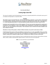
2.6 COMPATIBILITY OF CONNECTORS: Connectors are considered to be compatible with connecting elements when they
have been designed to work together in such a way that their sizes and shapes do not cause their gate mechanisms to
inadvertently open regardless of how they become oriented. Contact 3M if you have any questions about compatibility.
Connectors (hooks, carabiners, and D-rings) must be capable of supporting at least 5,000 lbs. (22.2 kN). Connectors
must be compatible with the anchorage or other system components. Do not use equipment that is not compatible.
Non-compatible connectors may unintentionally disengage (see Figure 5). Connectors must be compatible in size, shape,
and strength. Self-locking snap hooks and carabiners are required. If the connecting element to which a snap hook or
carabiner attaches is undersized or irregular in shape, a situation could occur where the connecting element applies a
force to the gate of the snap hook or carabiner (A). This force may cause the gate to open (B), allowing the snap hook or
carabiner to disengage from the connecting point (C).
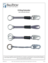
2.7 MAKING CONNECTIONS: Snap hooks and carabiners used with this equipment must be self-locking. Ensure all
connections are compatible in size, shape and strength. Do not use equipment that is not compatible. Ensure all
connectors are fully closed and locked. 3M connectors (snap hooks and carabiners) are designed to be used only as
specied in each product’s user’s instructions. See Figure 6 for examples of inappropriate connections. Do not connect
snap hooks and carabiners:
A. To a D-ring to which another connector is attached.
B. In a manner that would result in a load on the gate. Large throat snap hooks should not be connected to standard
size D-rings or similar objects which will result in a load on the gate if the hook or D-ring twists or rotates, unless the
snap hook is equipped with a 3,600 lb (16 kN) gate.
C. In a false engagement, where size or shape of the mating connectors are not compatible and, without visual
conrmation, the connectors seem fully engaged.
D. To each other.
E. Directly to webbing or rope lanyard or tie-back (unless the manufacturer’s instructions for both the lanyard and
connector specically allows such a connection).
F. To any object which is shaped or dimensioned such that the snap hook or carabiner will not close and lock, or that
roll-out could occur.
G. In a manner that does not allow the connector to align properly while under load.
Table 1 Inspection Schedule
Type of Use Application Examples Conditions of Use
Inspection Frequency
Competent Person
Infrequent to Light Rescue and Conned Space,
Factory Maintenance
Good Storage Conditions, Indoor or Infrequent
Outdoor Use, Room Temperature, Clean Environments
Annually
Moderate to Heavy Transportation, Residential
Construction, Utilities, Warehouse
Fair Storage Conditions, Indoor and Extended Outdoor
Use, All Temperatures, Clean or Dusty Environments
Semi-Annually to
Annually
Sever to Continuous Commercial Construction, Oil and
Gas, Mining
Harsh Storage Conditions, Prolonged or Continuous
Outdoor Use, All Temperatures, Dirty Environment
Quarterly to Semi-
Annually
1 Authorized Person: A person assigned by the employer to perform duties at a location where the person will be exposed to a fall hazard.
2 Rescuer: Person or persons other than the rescue subject acting to perform an assisted rescue by operation of a rescue system.
3 Competent Person: An individual designated by the employer to be responsible for the immediate supervision, implementation, and monitoring of the
employer’s managed fall protection program who, through training and knowledge, is capable of identifying, evaluating, and addressing existing and potential fall
hazards, and who has the employer’s authority to take prompt corrective action with regard to such hazards.
16
2.8 SELF-RETRACTING DEVICES WITH LEADING EDGE (SRD-LE): The SRDs covered by this instruction manual include
Self-Retracting Devices with Leading Edge capabilities (SRD-LEs). See Figure 1 for specic SRD-LE models. SRD-LEs were
tested for horizontal use and falls over a steel edge without burrs. SRD-LEs may be used in situations where a fall may
occur over steel edges, such as found on steel shapes or metal sheeting.
Leading Edge Precautions: Observe the following precautions when using SRD-LEs:
The allowable angle of redirection of the lifeline portion of the SRD-LE at the edge over which a fall might occur
(measured between the two sides formed by the redirected lifeline) shall be at least 90 degrees (see Figure 7).
The anchor point shall be situated at the same height as the edge at which a fall might occur or above the edge.
Anchor points below the edge are dangerous because they cause the lifeline to redirect at an angle sharper than 90
degrees (see Figure 7).
Consult Section 1 for limitations to the allowable work area relative to the anchorage point, including factors such
as swing fall and abrasion on the line at the edge and the use of a single anchor point versus anchors that allow
horizontal movement (e.g., Horizontal Lifeline or Horizontal Rail).
SRD-LEs may be used with a Horizontal Lifeline or Horizontal Rail only as instructed in the product instructions for the
Horizontal Lifeline or Horizontal Rail.
Do not work on the far side of an opening opposite the SRD-LE anchorage point.
In the event of a fall over the edge, special rescue measures may be required.
When planning your Leading Edge application, be sure work area parameters are within the Minimum Setback
Distance, Maximum Free Fall Distance, and Minimum Fall Clearance Required when Falling Over an Edge as indicated
on the SRD-LE labeling.
Leading Edge Fall Clearance Calculation: The Minimum Fall Clearance Required when Falling Over an Edge can be
calculated based on the Setback Distance and Distance Along the Edge of your Leading Edge application (see Figure 8). To
calculate Fall Clearance from the table in Figure 8:
1. Select the value closest to your Setback Distance (A) in the left-side row headings.
2. Select the value closest to your working Distance Along the Edge (B) from the top column headings. Shaded areas
with no values indicate the Distance Along the Edge is outside of the safe Work Radius for your selected Setback
Distance.
3. The Clearance Required when Falling Over an Edge (C) will be the value listed at the intersection of the row selected
in Step 1 and the column selected in Step 2.
4. Repeat the previous steps for every edge over which the worker could potentially fall to determine safe placement of
anchorage and allowable Work Radius.
CE SharpVG 11.60 revision 6 VG 11.54 revision 6
17
3.0 Installation
3.1 PLANNING: Plan your fall protection system before starting your work. Account for all factors that may aect your safety
before, during, and after a fall. Consider all requirements and limitations dened in this manual.
3.2 ANCHORAGE: Figure 9 illustrates typical SRL anchorage connections. The anchorage (A) should be directly overhead to
minimize Free Fall and Swing Fall hazards (see Section 2). Select a rigid anchorage point capable of sustaining the static
loads dened in Section 2.2. The Swivel Eye on the SRL is equipped with a Carabiner (B). Attach the Carabner directly to
the anchorage structure (rebar, angle iron, etc.), a Tie-O Adaptor (C), or Anchorage Connection Point (D).
3.3 HARNESS CONNECTION: A Full Body Harness is required for Fall Arrest applications. Connect the Snap Hook (A) on
the SRL Lifeline to the Back Dorsal D-Ring (B) on the Full Body Harness. (see Figure 10). For situations such as ladder
climbing, it may be useful to connect to the front Sternal D-Ring. Consult the harness manufacturer’s instructions for
details regarding use of the harness connection points.
3.4 TRIPOD MOUNTING: Figure 11 illustrates installation of the Ultra-Lok Self-Retracting Device with Retrieval Hand-Crank
on a DBI-SALA Tripod. The SRD-R is mounted on a leg of the Tripod and the Lifeline is routed through a Pulley System on
the Head of the Tripod:
1. Secure the Quick Mount Bracket on the leg of the Tripod: Assemble the Quick Mount Bracket around the Upper
Tube of the Tripod Leg. Position the Quick Mount Bracket at least 12 in. (30 cm) above the Locking Pin on the Tripod
Leg and then tighten the mounting bolts to 15 ft-lbs (20 Nm). Do not overtighten the bolts.
;
Never mount the Quick Mount Bracket on the Lower (Telescoping) Tube of the Tripod Leg.
2. Secure the SRL Mounting Bracket on the Quick Mount Bracket: Position the notches in the SRL Mounting
Bracket over the Rod Ends protruding from the Quick Mount Bracket and then pivot the SRL toward the Tripod Leg
until the holes in the SRL Mounting Bracket align with the holes in the Quick Mount Bracket. Insert the Mounting Pin
through the holes in the SRL Mounting Bracket and Quick Mount Bracket.
3. Route the SRL Lifeline over the Tripod Head Mount Pulleys: Remove the two Retainer Pins from the Head
Mount. Position the SRL Lifeline cable in the grooves in the two Head Mount Pulleys. Reinsert the Retainer Pins
through the Head Mount.
4.0 OPERATION
;
First time or infrequent users of Ultra-Lok Self-Retracting Devices (SRDs) should review the “Safety Information” at
the beginning of this manual prior to use of the SRD.
4.1 BEFORE EACH USE: Before each use of this fall protection equipment carefully inspect it to assure it is in good working
condition. Check for worn or damaged parts. Ensure all bolts are present and secure. Check that the lifeline is retracting
properly by pulling out the line and allowing it to slowly retract. If there is any hesitation in retraction the unit should be
marked as “UNUSABLE” and returned to an authorized service center for service. Inspect the lifeline for cuts, frays, burns,
crushing and corrosion. Check locking action by pulling sharply on the line. See Section 5 for inspection details. Do not use if
inspection reveals an unsafe condition.
4.2 AFTER A FALL: Any equipment which has been subjected to the forces of arresting a fall or exhibits damage consistent
with the effect of fall arrest forces as described in Section 5, must be removed from service immediately, marked as
“UNUSABLE”, and inspected and serviced as instructed in Sections 5 and 6.
4.3 BODY SUPPORT: A full body harness must be worn when using DBI-SALA SRLs. For general fall protection use, connect
to the back Dorsal D-Ring. For situations such as ladder climbing, it may be useful to connect to the front Sternal D-Ring.
Consult the harness manufacturer’s instructions for details regarding use of the harness connection points.
4.4 MAKING CONNECTIONS: When using a hook to make a connection, ensure roll-out cannot occur (see Figure 5). Do not
use hooks or connectors that will not completely close over the attachment object. Do not use non-locking snap hooks.
The mounting surface should meet the anchorage strength requirements stated in section 2.2. Follow the manufacturer’s
instructions supplied with each system component.
4.5 OPERATION: Inspect the SRL as described in section 5.0. Connect the SRL to a suitable anchorage or anchorage
connector as previously described. Connect the Self-Locking Snap Hook on the end of the lifeline to the Dorsal D-Ring on
the Full Body Harness (see Figure 10). Ensure connections are compatible in size, shape, and strength. Ensure hook is
fully closed and locked. Once attached, the worker is free to move about within the recommended working area at normal
speeds. If the RSQ Selection Knob is set to ‘Fall Arrest’, the SRL will arrest the fall. If the RSQ Selection Knob is set to
‘Descent’, the SRL will automatically descend the user to a lower level when a fall occurs. When working with an SRL,
always allow the lifeline to recoil back into the device under control. A tag line may be required to extend or retract the
lifeline during connection and disconnection operations. A tag line can be used to prevent uncontrolled retraction of the
lifeline into the SRL. Depending on the work site environment and conditions, it may be necessary to restrain the free end
of the tag line to prevent interference and entanglement with equipment or machinery.
18
4.6 RSQ™ FALL ARREST/DESCENT MODE SELECTION: DBI-SALA RSQ™ Dual-Mode SRLs are equipped with an RSQ Knob
to select between the Fall Arrest or Descent operating modes of the SRL (see Figure 12). To select Fall Arrest Mode or
Descent Mode:
1. Pull the RSQ™ Engagement Knob outward.
2. Turn the RSQ™ Engagement Knob until the arrow on the face of the knob points to Descent Mode (A) or Fall Arrest
Mode (B) and the RSQ™ Engagement Knob clicks into place with the Selection Notch (as illustrated in Figure 12).
RSQ Descent Mode: In Descent Mode, the user automatically descends to a lower level when a fall occurs.
RSQ Fall Arrest Mode: In Fall Arrest Mode, the SRD arrests the fall and the user remains suspended. Descent is
activated and controlled with the RSQ™ Engagement Knob Pull Ring or an optional Extension Pole Release Tool (see Figure
13):
Engagement Knob Pull Ring: Figure 13 illustrates operation of the Engagement Knob Pull Ring. To disengage Fall
Arrest Mode and initiate descent, grasp the Pull Ring and pull the Engagement Knob straight out (A). To stop descent;
release the Pull Ring to re-engage Fall Arrest Mode (B). To fully engage Descent Mode so descent continues without
pulling the Pull Ring, turn the Engagement Knob counter-clockwise (C) until the arrow on face of the knob points to
the Descent Selection Notch (see Figure 12).
;
80 lbs - 100 lbs (0.36 kN - 0.45 kN) of pulling force is required to release the RSQ™ Engagement Knob from
Fall Arrest Mode.
Extension Pole Release Tool: Insert the Extension Pole Release Tool from any direction so the ends of the Release
Forks surround the base of the RSQ™ Engagement Knob below the Knurled Ridge and Pull Ring (see Figure 13D).
To disengage Fall Arrest Mode and initiate descent, push forward on the Extension Pole until the RSQ™ Engagement
Knob is fully lodged in the Release Fork. Descent will continue as long as the Release Fork is fully lodged between the
RSQ™ Engagement Knob and the Housing. Removal of Release Fork may cause unit to re-engage Fall Arrest Mode.
;
The Release Fork on the Extension Pole Release tool is tapered to push the RSQ™ Engagement Knob straight
out as the fork is pushed forward on the knob. It is not necessary to pry the knob with the Extension Pole. Prying
could break o the knob.
;
Ultra-Lok RSQ SRLs are designed for emergency fall arrest and descent and may only be used for a single, vertical
descent. If the SRL is used to descend, remove it from service immediately and send it to an authorized service center for
repair.
4.7 RETRIEVAL OPERATION: Figure 14 illustrates operation of the Integral Rescue Hand Crank on the Ultra-Lok Retrieval
SRL-R. Do not attempt to operate Retrieval with the lifeline fully retracted. To activate Retrieval mode and use the Rescue
Hand Crank:
1. Loosen the Locking Thumb Screw to release the Crank Arm.
2. Rotate the Retrieval Handle up from the SRL Body 90°.
3. Pull and hold the Shift Knob in the unlocked position.
4. Push the Crank Arm in and release the Shift Knob to engage. If needed, rotate the Crank Arm clockwise to help
engage the gear.
5. Raise and lower the Lifeline as illustrated in Figure 14:
A. To Raise: Rotate the Crank Arm clockwise.
B. To Lower: Rotate the Crank Arm counterclockwise. After fall arrest; crank the Crank Arm clockwise slightly first
to release the Fall Arrest Brake, then crank the Crank Arm counterclockwise.
;
The Integral Rescue Hand Crank on 3-Way Emergency Retrieval SRL-R models is for rescue purposes only and
should not be used for work positioning or material lifting/lowering.
;
DBI-SALA SRL-Rs do not incorporate an Overload Clutch to limit the force exerted on the drive components and
attached person. Avoid line slack while in Retrieval mode. Also, monitor the individual during retrieval to ensure they
are not subjected to excessive force from continued lifting after entanglement on an obstruction.
;
A minimum load of 75 lbs (33.9 kg) is required to lower or pay out the Lifeline. A force of 30 lbs (0.13 kN) is
required to operate the Retrieval system when loaded to capacity.
;
Stop cranking when the Lifeline is fully extended or retracted. Continued cranking can damage components.
19
4.8 RETRIEVAL DISENGAGEMENT: To disengage Retrieval mode:
;
When Retrieval mode is disengaged, any extended Lifeline will retract into the SRL. To avoid possible injury, retract
the Lifeline prior to disengagement or hold onto the Lifeline.
1. Remove any load from the Lifeline.
2. Pull and hold the Shift Knob in the unlocked position.
3. Pull the Crank Arm out to disengage and then release the Shift Knob.
4. Pull out and rotate the Retrieval Handle down toward the SRL Body to stowed position.
5.0 Inspection
5.1 RFID TAG: The Self-Retracting Device includes a Radio Frequency Identication (RFID) tag (see Figure 15). The RFID tag
can be used in conjunction with the handheld reading device and web based portal to simplify inspection and inventory
control and provide records for your fall protection equipment. For details, contact a 3M Customer Service representative
(see back cover). Follow the instructions provided with your handheld reader, or on the web portal, to transfer your data
to your web log.
5.2 INSPECTION FREQUENCY: The Ultra-Lok Self-Retracting Device must be inspected at the intervals dened in
Section 2.2 -
Inspection Frequency”. Inspection procedures are described in the “Inspection & Maintenance Log” (Table
2).
;
Extreme working conditions (harsh environments, prolonged use, etc.) may require increasing the frequency of
inspections.
5.3 UNSAFE OR DEFECTIVE CONDITIONS: If inspection reveals an unsafe defective condition, remove the
Self-Retracting Device from service immediately, mark as “UNUSABLE”, and send to an authorized service center for
repair.
;
Only 3M or parties authorized in writing may make repairs to this equipment.
5.4 PRODUCT LIFE: The functional life of DBI-SALA Self-Retracting Devices is determined by work conditions and
maintenance. As long as the product passes inspection criteria, it may remain in service.
6.0 MAINTENANCE, SERVICE, and STORAGE
6.1 CLEANING: Cleaning procedures for the Self-Retracting Device are as follows:
Periodically clean the exterior of the SRL using water and a mild soap solution. Position the SRD so excess water can
drain out. Clean labels as required.
Clean lifeline with water and mild soap solution. Rinse and thoroughly air dry. Do not force dry with heat. An
excessive buildup of dirt, paint, etc. may prevent the lifeline from fully retracting back into the housing causing a
potential free fall hazard. Replace lifeline if excessive buildup is present.
6.2 SERVICE: Additional maintenance and servicing procedures must be completed by an authorized service center. Do not
attempt to disassemble the SRL or lubricate any parts.
6.3 STORAGE AND TRANSPORT: Store and transport Self-Retracting Device in a cool, dry, clean environment out of direct
sunlight. Avoid areas where chemical vapors may exist. Thoroughly inspect the SRL after any period of extended storage.
7.0 Labels
Figure 23 illustrates labels on the the Ultra-Lok SRDs and their locations. All label must be present on the SRL.
Labels must be replaced if they are not fully legible.
20
Table 2 Inspection & Maintenance Log
Serial Number(s): Date Purchased:
Model Number: Date of First Use:
Inspected By: Inspection Date:
Component: Inspection:
Before
Each Use
Competent
Person
SRL
(Figure 16)
Inspect for loose bolts and bent or damaged parts.
Inspect Housing (A) for distortion, cracks, or other damage.
Inspect the Swivel Eye (B) for distortion, cracks, or other damage. The Swivel Eye should be attached
securely to the SRL, but should pivot freely.
The Lifeline (C) should pull out and retract fully without hesitation or creating a slack line condition.
Ensure device locks up when lifeline is jerked sharply. Lockup should be positive with no slipping.
NOTE: SRLs with RSQ should be in Fall Arrest Mode for this test (see Figure 12)
The labels must be present and fully legible (see Figure 23).
Look for signs of corrosion on the entire unit.
Swivel Snap Hook & Impact
Indicator
(Figure 17)
Inspect the Swivel Snap Hook for signs of damage, corrosion, and working condition. Swivel should
rotate freely. Inspect the Impact Indicator. If the Red Band is displayed (Indicated Mode), impact
loading has occurred and the SRL must be removed from service and inspected. Do not attempt to
reset the Impact Indicator. Return the SRL to an authorized service center for resetting. NOTE: The
Swivel will not turn freely when the Impact Indicator is in Indicated Mode.
Wire Rope Lifeline
(Figure 18)
Inspect wire rope for cuts, kinks (A), broken wires (B), bird-caging (C), welding splatter, (D)
corrosion, chemical contact areas, or severely abraded areas. Slide the cable bumper up and inspect
ferrules for cracks or damage and inspect the wire rope for corrosion and broken wires. Replace the
wire rope assembly if there are six or more randomly distributed broken wires in one lay, or three or
more broken wires in one strand in one lay. A “lay” of wire rope is the length of wire rope it takes for
a strand (the larger groups of wires) to complete one revolution or twist along the rope. Replace the
wire rope assembly if there are any broken wires within 1 inch (25 mm) of the ferrules.
Reserve Lifeline
(Figure 19)
Inspect the reserve lifeline payout. If a fall has been arrested with most of the lifeline out, the reserve
lifeline may have been deployed. Pull the lifeline out of the SRL until it stops. If a red band is visible,
the reserve lifeline is spent and the unit must be serviced by an authorized service center before
reuse.
RSQ Components
(Figure 20)
A hand pull test should be performed on RSQ™ Components prior to each use:
1. Set RSQ Engagement Knob to Descent position (Figure 20).
2. Grasp the lifeline and pull rmly to engage descent mechanism.
3. Continue to smoothly pull out approximately 3 feet (1 m) of cable. Steady resistance should be
felt when pulling out cable.
Retrieval Integral Rescue Hand
Crank
(Figure 21)
Inspect the Crank Arm (A) for distortion or other damage. Ensure that the Retrieval Handle (B) can be
folded out and secured in the cranking position.
Ensure the Retrieval Shift Knob (C) can be pulled out to the unlocked position and then released,
locking the Crank Arm in both the engaged and disengaged positions.
Test the retrieval feature for proper operation by raising and lowering a test weight of at least 75 lbs
(34 kg). When the Retrieval Handle is released, the weight should not move and the Retrieval Handle
should remain in position (no movement). A ‘clicking’ sound should be audible when raising the load.
SRL-LE Energy Absorber
(Figure 22)
On Self-Retracting Lanyards with Leading Edge capability (SRL-LEs) verify that the integral Energy
Absorber has not been activated. There should be no webbing pulled out of the cover (A). The cover
should be secure and free of tears (B) or other damage.
Corrective Action/Maintenance: Approved By:
Date:
Corrective Action/Maintenance: Approved By:
Date:
Corrective Action/Maintenance: Approved By:
Date:
Corrective Action/Maintenance: Approved By:
Date:
Corrective Action/Maintenance: Approved By:
Date:
Corrective Action/Maintenance: Approved By:
Date:
Corrective Action/Maintenance: Approved By:
Date:
Corrective Action/Maintenance: Approved By:
Date:
Corrective Action/Maintenance: Approved By:
Date:
  • Page 1 1
  • Page 2 2
  • Page 3 3
  • Page 4 4
  • Page 5 5
  • Page 6 6
  • Page 7 7
  • Page 8 8
  • Page 9 9
  • Page 10 10
  • Page 11 11
  • Page 12 12
  • Page 13 13
  • Page 14 14
  • Page 15 15
  • Page 16 16
  • Page 17 17
  • Page 18 18
  • Page 19 19
  • Page 20 20
  • Page 21 21
  • Page 22 22
  • Page 23 23
  • Page 24 24

3M DBI-SALA® Ultra-Lok™ Heavy-Duty Self Retracting Lifeline, Cable 3504485, 1/CV Operating instructions

Type
Operating instructions

Ask a question and I''ll find the answer in the document

Finding information in a document is now easier with AI