
AH 0538
Valid from manufacturing week 1050458 496 001 010330
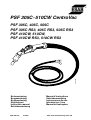
PSF 305C- 510CW CentroVac
PSF 305C, 405C, 505C
PSF 305C RS3, 405C RS3, 505C RS3
PSF 410CW, 510CW,
PSF 410CW RS3, 510CW RS3
Bruksanvisning
Brugsanvisning
Bruksanvisning
Käyttöohjeet
Instruction manual
Betriebsanweisung
Manuel d’instructions
Gebruiksaanwijzing
Instrucciones de uso
Istruzioni per l’uso
Manual de instruções

-- 2 --
Rätt till ändring av specifikationer utan avisering förbehålles.
Ret til ændring af specifikationer uden varsel forbeholdes.
Rett til å endre spesifikasjoner uten varsel forbeholdes.
Oikeudet muutoksiin pidätetään.
Rights reserved to alter specifications without notice.
Änderungen vorbehalten.
Sous réserve de modifications sans avis préalable.
Recht op wijzigingen zonder voorafgaande mededeling voorbehouden.
Reservado el derecho de cambiar las especificaciones sin previo aviso.
Ci riserviamo il diritto di variare le specifiche senza preavviso.
Reservamo--nos o direito de alterar as especificações sem aviso prévio.
SVENSKA 3..............................................
DANSK 9................................................
NORSK 15................................................
SUOMI 21................................................
ENGLISH 27..............................................
DEUTSCH 33.............................................
FRANÇAIS 39.............................................
NEDERLANDS 45.........................................
ESPAÑOL 51..............................................
ITALIANO 57..............................................
PORTUGUÊS 63..........................................

ENGLISH
-- 2 7 --
TOCe
1 DIRECTIVE 28........................................................
2SAFETY 28...........................................................
3 INTRODUCTION 29...................................................
4 TECHNICAL DATA 29.................................................
5 CONSUMABLES 30...................................................
5.1 Contact nozzle 30............................................................
5.2 Electrode conductor 30.......................................................
5.3 Replacing electrode conductors 30.............................................
5.4 Gas nozzle 31...............................................................
5.5 Gas protection 31............................................................
5.6 Gas flow meter 31............................................................
6 OPERATION 32.......................................................
7 MAINTENANCE 32....................................................
8 SPARE PARTS AND ACCESSORIES 32.................................
SPARE PARTS LIST 69...................................................
ACCESSORIES 78.......................................................

-- 2 8 --
bg09d1ea
1 DIRECTIVE
DECLARATION OF CONFORMITY
ESAB Welding Equipment AB, S--695 81 Laxå, Sweden, gives its unreserved guarantee that torch
PSF 305C/405C/505C, PSF 305C RS3/405C RS3/505C RS3, PSF 410CW/510CW/410CW
RS3/510CW RS3 from number 105 complies with standard EN 60974--7, in accordance with the re-
quirements of directive (73/23/EEC).
-- -- -- -- -- -- -- -- -- -- -- -- -- -- -- -- -- -- -- -- -- -- -- -- -- -- -- -- -- -- -- -- -- -- -- -- -- -- -- -- -- -- -- -- -- -- -- -- -- -- -- -- -- -- -- -- -- -- -- -- -- -- -- --------
Joakim Cahlin
Vice President
ESAB Welding Equipment AB
695 81 LAXÅ
SWEDEN Tel: + 46 584 81000 Fax: + 46 584 411924
Laxå 2001--01--26
2SAFETY
WARNING
READ AND UNDERSTAND THE INSTRUCTION MANUAL BEFORE INSTALLING OR OPERAT ING.
ARC WELDING AND CUTTING CAN BE INJURIOUS TO YOURSELF AND OTHERS. TAKE PRECAU-
TIONS WHEN WELDING. ASK FOR YOUR EMPLOYER’S SAFETY PRACTICES WHICH SHOULD BE
BASED ON MANUFACTURERS’ HAZARD DATA.
ELECTRIC SHOCK -- Can kill
S Install and earth the welding unit in accordance with applicable standards.
S Do not touch live electrical parts or electrodes with bare skin, wet gloves or wet clothing.
S Insulate yourself from earth and the workpiece.
S Ensure your working stance is safe.
FUMES AND GASES -- Can be dangerous to health
S Keep your head out of the fumes.
S Use ventilation, extraction at the arc, or both, to keep fumes and gases from your breathing zone and
the general area.
ARC RAYS -- Can injure eyes and burn skin.
S Protect your eyes and body. Use the correct welding screen and filter lens and wear protective
clothing.
S Protect bystanders with suitable screens or curtains.
FIRE HAZARD
S Sparks (spatter) can cause fire. Make sure therefore that there are no inflammable materials nearby.
NOISE -- Excessive noise can damage hearing
S Protect your ears. Use ear defenders or other hearing protection.
S Warn bystanders of the risk.
MALFUNCTION -- Call for expert assistance in the event of malfunction.
PROTECT YOURSELF AND OTHERS!
GB

-- 2 9 --
bg09d1ea
3 INTRODUCTION
PSF 305C, 405C, 505C, 305C RS3, 405C RS3, 505C RS3, 410CW, 510CW, 410CW RS3 and 510C
WRS3 form a series of welding guns with smoke exhausters. The guns are available with either
self--cooling or water cooling systems and are of a swan--neck design.
PSF 305CRS3, 405CRS3, 410C WRS3 and 510C WRS3 guns feature program selectors that allow
you to change pre--set welding programs. (Programs are preset at the welding power source.)
Information about the construction of the guns and the spare parts available in the form of illustrations
and lists can be found in the spare parts register.
Welding guns are available in a variety of types; for more information see the spare parts register on
page 69.
A range of accessories including welding tips, swan--necks and contact nozzles are also available.
Details of ESAB’s welding gun accessories can be found on page 78.
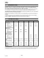
4 TECHNICAL DATA
Welding gun PSF 305C PSF 405C PSF 505C PSF 410CW PSF 510CW
Permittedloadat50%
intermittence
Carbon dioxide
CO
2
330 A 400 A 500 A 400 A 500 A
Mixed gas, Argon
(Al electrode)
300 A 350 A 440 A 350 A 440 A
Permittedloadat60%
intermittence
Carbon dioxide
CO
2
315 A 380 A 450 A -- --
Mixed gas, Argon
(Al electrode)
285 A 325 A 400 A -- --
Permittedloadat
100% intermittence
Carbon dioxide
CO
2
-- -- -- 380 A 460 A
Mixed gas, Argon
(Al electrode)
-- -- -- 325 A 410 A
Recommended gas
flow
10--15 l/min 11- -16 l/min 12--18 l/min 11--16 l/min 12--18 l/min
Electrode diameter 0.6--1.2 mm 0.6--1.6 mm 0.6--1.6 mm 0.6--1.6 mm 0.6--1.6 mm
Weight 3.0 m hose
package
4.4 kg 4.6 kg 4.8 kg 4.0 kg 4.1 kg
Weight 4.5 m hose
package
6.6 kg 6.8 kg 7.0 kg 6.2 kg 6.3 kg
Intermittance factor
The intermittence factor specifies the proportion of any ten minute period, expressed as a percentage,
during which it is possible to weld using a specific load without the welding gun being overloaded.
GB

-- 3 0 --
bg09d1ea
5 CONSUMABLES
5.1 Contact nozzle
The hole size of the contact nozzle is determined by the diameter of the electrode, the type of inert
gas and the level of current used. See accessories on page 78, tables 1--3.
When selecting a contact nozzle, you should first look at the short--arc table (CO
2
). Where sheaves
are produced at high welding temperatures with Argon or other inert gases, choose a contact nozzle
using the spray arc table.
5.2 Electrode conductor
The spiral steel wire guide that comes as standard with the welding gun can be used for all types of
electrode of the intended size, except those made from stainless steel or aluminium.
Teflon coated wire guides are suitable for welding with all types of electrode (Al, Ss, and Fe).
However , it is recommended that Teflon coated wire guides are not used when welding using Fe and
CW electrodes that are thicker than 1.2 mm due to the increased instance of wear. Teflon coated wire
guides produce less friction but have a considerably shorter life than the standard steel spiral.
In order to ensure that you enjoy a satisfactory level of wire feed, select a wire guide using table 4 on
page 80.
5.3 Replacing electrode conductors
1. Fit the correct nipple
ESAB Connection EURO Connection
NB
Each wire guide is supplied with 2 nipples, 1 for ESAB connection and 1 for EURO
connection.
2. Remove the gas cover and middle nozzle.
3. Fit the wire guide in the hose package.
a) Turn the connecting section clockwise until resistance is met
b) The wire guide should go in
GB

-- 3 1 --
bg09d1ea
4. Cut the wire guide to the correct length.
During cutting, the welding gun must be extended with the wire guide fully inserted into the rear
connector. Cut the wire guide using a projectile “X” as shown in the table below .
Welding gun Length Adapter Size X
PSF 305C, PSF 305C RS3 3,0 m 0366 394 001 21 mm
PSF 305C, PSF 305C RS3 4,5 m 0366 394 001 25 mm
PSF 405C, PSF 405C RS3 3,0 m 0366 394 002 15 mm
PSF 405C, PSF 405C RS3 4,5 m 0366 394 002 21 mm
PSF 505C, PSF 505C RS3 3.0 m 0366 395 001 21 mm
PSF 505C, PSF 505C RS3 4.5 m 0366 395 001 21 mm
PSF 410CW, PSF 410CW RS3 3.0 m 0366 394 002 20 mm
PSF 410CW, PSF 410CW RS3 4.5 m 0366 394 002 25 mm
PSF 510CW, PSF 510CW RS3 3.0 m 0366 394 002 20 mm
PSF 510CW, PSF 510CW RS3 4.5 m 0366 394 002 25 mm
No sharp edges must be present on the inside of the wire guide after cutting.
5. Re-- fit the middle nozzle and gas cover
6. Fit the welding gun on the machine.
5.4 Gas nozzle
There is a spray protector fitting inside the gas nozzle. This must be in position during welding in order
to prevent the welding spray jamming and thereby causing a short circuit in the swan--neck.
Gas nozzles with larger and smaller openings are available as accessories for each type of gun. See
the spare parts list for more details.
5.5 Gas protection
Several factors come into play for good gas protection. The most important ones are:
1. Selection of inert gas -- Mixed gas and Argon require a greater flow than carbon dioxide
2. Set flow quantity -- See Technical data (to be measured at the gas nozzle).
3. Set welding current -- High welding currents require greater gas flows.
4. Position of welding joint -- A vertical position requires greater gas flow
5. T ype of welding joint -- External corner joints require a greater gas flow than butt joints.
Conversely, fillet joints require a lower gas flow.
6. Smoke evacuation on gun -- Using smoke evacuation increases the need for inert gas by
10--12%
7. Angle of welding gun to
the job.
-- Angling the gun at less than 45˚ may result in poor gas protec-
tion.
5.6 Gas flow meter
A gas flow meter to measure gas flow through the gun is available as an accessory
(item no. 0155 716 880).
GB

-- 3 2 --
bg09d1ea
6 OPERATION
General safety regulations for the handling of the equipment appear from
page 28. Read through before you start using the equipment!
7 MAINTENANCE
A regular programme of care and maintenance reduces unnecessary and expensive downtime.
1. Welding spray in the gas nozzle diminishes gas protection and increases the danger of
spark--over.
--Clean the equipment on a regular basis and use sparing amounts of welding paste or welding
spray.
2. The spray protector in the gas nozzle must be replaced once its front end wears thin.
3. Each time an electrode bobbin is changed, the welding hose should be removed from the supply
unit and blown clean with compressed air.
4. The electrode end must not have sharp edges when inserted into the wire guide. This is
especially important when using Teflon coated wire guides.
Integrated smoke evacuation
The inside of this welding gun is technically similar to the standard PSF gun. For information on
specific spare parts, see the spare parts register.
You can tailor the level of suction by opening the damper on the topside of the handle.
Suction source for welding guns with integrated smoke evacuation
In order to achieve full suction power, the smoke evacuation gun must be connected to a suction
source where pressure does not fall below 15 kPa.
Cleaning welding guns with integrated smoke evacuation
In order to maintain a constant level of suction, the inside of the gun handle should be cleaned on a
regular basis. The appropriate length of time between cleans is dependant on how often the
equipment is used and the amount of dust and oil contained in the welding smoke.
8 SPARE PARTS AND ACCESSORIES
PSF 305C/405C/505C, PSF 305C RS3/405C RS3, 505C RS3, PSF 410CW/510CW, PSF
410CW RS3/510CW RS3 is designed and tested in accordance with the international an
European standards IEC/EN 60974--7 and EN 60974--7.
It is the obligation of the service unit which has carried out the service or repair work
to make sure that the product still conforms to the said standard.
You can order spare parts and accessories through your local ESAB representative. Their contact
details can be found on the last page of this booklet. When placing an order, specify the product type,
serial number , designation and spare part number as shown in the spare parts register . This facilitates
shipping and ensures that you get the part you want.
GB
-
 1
1
-
 2
2
-
 3
3
-
 4
4
-
 5
5
-
 6
6
-
 7
7
-
 8
8


ESAB PSF 505C RS3 User manual
- Category
- Welding System
- Type
- User manual
Ask a question and I''ll find the answer in the document
Finding information in a document is now easier with AI
Related papers
-
ESAB PSF 405 RS3 User manual
-
ESAB 510W User manual
-
ESAB OCE 2H User manual
-
-
-
ESAB PKB 400 User manual
-
ESAB ESABFeed 48-4 M14 User manual
-
ESAB YardFeed 2000, Origo™ YardFeed 2000, Aristo® YardFeed 2000 User manual
-
-
