Page is loading ...

DUAL DISPLAY L/C/R METER
MZ-505C
- 0 MI1972 -


NOTAS SOBRE SEGURIDAD
Antes de manipular el equipo leer el manual de instrucciones y muy
especialmente el apartado PRESCRIPCIONES DE SEGURIDAD.
El símbolo sobre el equipo significa "CONSULTAR EL
MANUAL DE INSTRUCCIONES". En este manual puede aparecer
también como símbolo de advertencia o precaución.
Recuadros de ADVERTENCIAS Y PRECAUCIONES pueden
aparecer a lo largo de este manual para evitar riesgos de accidentes
a personas o daños al equipo u otras propiedades.
SAFETY NOTES
Read the instruction manual before using the equipment, mainly
"SAFETY RULES" paragraph.
The symbol on the equipment means "SEE USER’S
MANUAL". In this manual may also appear as a Caution or Warning
symbol.
Warning and Caution statements may appear in this manual to
avoid injury hazard or damage to this product or other property.


SUMARIO
CONTENTS
) Manual español ...............................................................
)
English manual................................................................


INSTRUCTION MANUAL. MZ-505C
TABLE OF CONTENTS
1 GENERAL .....................................................................................1
1.1 Introduction .........................................................................1
1.2 Specifications......................................................................2
2 SAFETY RULES ...........................................................................7
3 OPERATING INSTRUCTIONS .....................................................9
3.1 Description of the controls and elements............................9
3.2 LCD Display illustration.....................................................11
3.3 How to operate..................................................................13
3.3.1 Inductance measurement............................................13
3.3.2 Capacitance measurement .........................................14
3.3.3 Resistance measurement............................................15
4 OPERATING INSTRUCTIONS ...................................................17
4.1 Autopower down ...............................................................17
4.1.1 Continuous Mesurement .............................................17
4.1.2 Power Switch...............................................................17
4.2 Frequency select...............................................................18
4.3 Parallel/Series mode.........................................................18
4.4 RANGE Button..................................................................18
4.5 L/C/R Function button (only main indicator)......................19
4.6 Q/ D/ R FUNCTION BUTTON (secondary display)...........19
4.7 HOLD. > 2sec. ..................................................................19
4.8 MIN/ MAX BUTTON..........................................................20
4.9 SET ...................................................................................21
4.10 REL. Relative mode (only Main display) ...........................23
4.11 HI/LO LIMITS ....................................................................24
4.12 TOL ...................................................................................24
4.13 Automatic fuse status detection ........................................25
4.14 Calibration .........................................................................26
4.15 Low battery indication .......................................................27

User’s manual. MZ-505C
5 MAINTENANCE ..........................................................................29
5.1 Service ..............................................................................29
5.2 Battery replacement..........................................................29
5.3 Fuse replacement .............................................................30
5.4 Cleaning recommendations ..............................................31

INSTRUCTION MANUAL. MZ-505C
04/2015 Page 1
DUAL DISPLAY L/C/R METER
MZ-505C
1 GENERAL
1.1 Introduction
This 19.999 count L/C/R hand-held meter is a special
microprocessor-controlled meter for measuring functions of
inductance, capacitance and resistance. Simple to operate, the
instrument not only takes absolute parallel mode measurements, but
also capable of series mode measurement. The meter provides
direct and accurate measurements of inductors, capacitors and
resistors with different testing frequencies. It is selectable for auto
and manual ranging.
Front panel pushbuttons maximize the convenience of function
and feature selection such as data hold; maximum, minimum and
average record mode; relative mode; tolerance sorting mode;
frequency and L/C/R selection.
The test data can be transferred to PC through an full isolated
optical RS232C interface.
A tilt stand provides position flexibility for viewing and operating
the meter. The over-melding plastic and rubber case protects the
meter to be stronger. With single 9V battery operation is standard for
the meter, a DC 12V power adaptor can also be used as an optional
power input.

INSTRUCTION MANUAL. MZ-505C
Page 2 04/2015
1.2 Specifications
Parameters measured L
S
+ (Q, D, RS), L
P
+ (Q, D, RP), C
S
+ (Q, D, RS), C
P
+ (Q, D, RP).
Displays
L/C/R Maximum Display 4 ½ digit 19999
counts.
Q/D/R Display 4 digit 999.9 count
maximum (Autoranging).
Measuring ranges
C (120 Hz) 1 pF ~ 10 mF (basic accuracy
0.7 %).
C (1 kHz) 0.1 pF ~ 1000 μF (basic accuracy
0.7 %).
L (120 Hz) 1 μH ~ 10000 H (basic accuracy
0.7 %).
L (1 kHz) 0.1 μH ~ 1000 H (basic accuracy
0.7 %).
R 1 mΩ ~ 10 MHΩ (basic accuracy
0.5 %).
Resolution
R Up 0.001 Ω.
L Up 0.1 μH.
C Up 0.1 pF.
Ranging mode Auto & Manual.
Measuring terminals 2 terminals with sockets.
Test frequency 1 KHz, 120 Hz.
Tolerance mode 1 %, 5 %, 10 %, 20 %.
Measuring rate 1 measurement x seconds, nominal.
Response time Approx. 1 second at manual range.
Auto power-off 10 minutes approx. without
operation.
Temperature coefficient 0,15 x (specific accuracy)/°C
(0-18 °C and 28-40 °C).

INSTRUCTION MANUAL. MZ-505C
04/2015 Page 3
Low battery indicator The symbol
+
-
appears on the
screen.
Voltage measurement 600 mV AC.
Input protection Fuse.
POWER SUPPLY
Internal Battery 9 V IEC6F22.
External 12 to 15 V DC.
Consumption Aprox. 12 mA for operation
0.03 mA After auto power-off
Operating environmental conditions
Altitude Up to 2000 m
Temperature range From 0 °C to 40 °C
Max. relative humidity 80 % (up to 31 °C), decreasing
lineally up to 50% at 40 °C
Mechanical properties
Dimensions L. 91 x W. 192 x H. 52,5 (mm).
Weight Aprox. 365 gr. (Accessories
Included).
Standard accessories Test alligator clips (pair).
Kit for RS-232 + software.
DC 9V battery (IEC 6F22 ).
Instruction Manual.
Optional accessories SMD Tweezers PP-009.

INSTRUCTION MANUAL. MZ-505C
Page 4 04/2015
Ranges and accuracies
Accuracy ± (% of reading ± num. of digits) at 23°C ±5°C, RH<75%.
Resistance
Test Frequency: 120 Hz / 1 KHz
Accuracy
Range
Maximum
Display
at 120 Hz at 1 KHz
Specified Note
10 MΩ 10 MΩ ±(2.0%+8 dig) ± (2.0%+8 dig)
After open cal.
2MΩ 1.9999MΩ ± (0.5%+5 dig) ± (0.5%+5 dig)
After open cal.
200kΩ 199.99kΩ ± (0.5%+3 dig) ± (0.5%+3 dig)
-
20kΩ 19.999kΩ ± (0.5%+3 dig) ± (0.5%+3 dig)
-
2kΩ 1.9999kΩ ± (0.5%+3 dig) ± (0.5%+3 dig)
-
200Ω 199.99Ω ± (0.8%+5 dig) ± (0.8%+5 dig)
After short cal.
20Ω 19.999Ω ± (1.2%+4 dig) ± (1.2%+4 dig)
After short cal.
Capacitance
Test Frequency: 120 Hz
Accuracy
Range
Maximum
Display
Capacity. DF
Specified
Note
20mF 10mF
± (5.0%+5 dig)
DF<0.1
± (10%+100/Cx+5 dig)
(DF<0.1)
After short
cal.
2000μF 1999.9μF
± (1.0%+5 dig)
DF<0.1
± (2%+100/Cx+5 dig)
(DF<0.1)
After short
cal.
200μF 199.99μF
± (0.7%+3 dig)
DF<0.5
± (0.7%+100/Cx+5 dig)
(DF<0.5)
-
20μF 19.999μF
± (0.7%+3 dig)
DF<0.5
± (0.7%+100/Cx+5 dig)
DF<0.5
-
2000nF 1999.9nF
± (0.7%+3 dig)
DF<0.5
± (0.7%+100/Cx+5 dig)
DF<0.5
-
200nF 199.99nF
± (0.7%+5 dig)
DF<0.5
± (0.7%+100/Cx+5 dig)
DF<0.5
After open
cal.
20nF 19.999nF
± (1.0%+5 dig)
DF<0.1
± (2%+100/Cx+5 dig)
DF<0.1
After open
cal.

INSTRUCTION MANUAL. MZ-505C
04/2015 Page 5
Test Frequency: 1 KHz
Accuracy
Range
Maximum
Display
Capacity. DF
Specified
Note
2000μF 1000.0μF
(2)
± (5.0%+5 dig)
DF<0.1
± (10%+100/Cx+5 dig)
DF<0.1
After short
cal.
200μF 199.99μF
(3)
± (1.0%+5 dig)
DF<0.1
± (2.0%+100/Cx+5 dig)
DF<0.1
After short
cal.
20μF 19.999μF
± (0.7%+3 dig)
DF<0.5
± (0.7%+100/Cx+5 dig)
DF<0.5
-
2000nF 1999.9nF
± (0.7%+3 dig)
DF<0.5
± (0.7%+100/Cx+5 dig)
DF<0.5
-
200nF 199.99nF
± (0.7%+3 dig)
DF<0.5
± (0.7%+100/Cx+5 dig)
DF<0.5
-
20nF 19.999nF
± (0.7%+5 dig)
DF<0.5
± (0.7%+100/Cx+5 dig)
DF<0.5
After open
cal.
2000pF 1999.9pF
± (1.0%+5 dig)
DF<0.1
± (2.0%+100/Cx+5 dig)
DF<0.1
After open
cal.
Notes: Q Value is the reciprocal of DF (dissipation factor).
This specification is based on the measurement performed
at the test socket.
Inductance
Test Frequency: 120 Hz
Accuracy
Range
Maximum
Display
Inductance DF
Specifie
d Note
20000H 10000H
unspecified unspecified
-
1000H 999.9H
± (1.0%+ Lx/10000% +5 dig)
DF<0.5
(2%+100/Lx+5 dig)
DF<0.5
After
open cal.
200H 199.99H
± (0.7%+ Lx/10000%+5 dig)
DF<0.5
(1.2%+100/Lx+5 dig)
DF<0.5
-
20H 19.999H
± (0.7%+ Lx/10000%+5 dig)
DF<0.5
(1.2%+100/Lx+5 dig)
DF<0.5
-
2000m 1999.9mH
± (0.7%+ (Lx/10000)%+5
dig) DF<0.5
(1.2%+100/Lx+5 dig)
DF<0.5
-
200m 199.99mH
± (1.0%+ Lx/10000%+5 dig)
DF<0.5
(3%+100/Lx+5 dig)
DF<0.5
After
short cal.
20m 19.999mH
± (2.0%+ Lx/10000%+5 dig)
DF<0.5
(10%+100/Lx+5 dig)
DF<0.5
After
short cal.

INSTRUCTION MANUAL. MZ-505C
Page 6 04/2015
Test Frequency: 1 KHz
Accuracy
Range
Maximu
m
Display
Inductance DF
Specifie
d Note
2000H 1000.0
unspecified unspecified
200H 199.99H
± (1.0%+ Lx/10000%+5 dig)
DF<0.5
± (2.0%+100/Lx+5 dig)
DF<0.5
After
open
cal.
20H 19.999H
± (0.7%+ Lx/10000%+5 dig)
DF<0.5
± (1.2%+100/Lx+5 dig)
DF<0.5
-
2000mH 1999.9mH
± (0.7%+ Lx/10000%+5 dig)
DF<0.5
± (1.2%+100/Lx+5 dig)
DF<0.5
-
200mH 199.99mH
± (0.7%+ Lx/10000%+5 dig)
DF<0.5
± (1.2%+100/Lx+5 dig)
DF<0.5
-
20mH 19.999mH
± (1.0%+ Lx/10000%+5 dig)
DF<0.5
± (3.0%+100/Lx+5 dig)
DF<0.5
After
short
cal.
2000μH 1999.9μH
± (2.0%+ Lx/10000%+5 dig)
DF<0.5
± (10%+100/Lx+5 dig)
DF<0.5
After
short
cal.
Notes: Q Value is the reciprocal of DF.
This specification is based on the measurement performed
at the test socket.

INSTRUCTION MANUAL. MZ-505C
04/2015 Page 7
2 SAFETY RULES
* The safety could not be assured if the instructions for use
are not closely followed.
* When measuring components in circuit you must previously
disconnect the power supply.
* When measuring capacitors is necessary to discharge them
previously.
* When using some of the following accessories use only the
specified ones to ensure safety:
Battery 9V 6F22.
* Observer all specified ratings both of supply and
measurement.
* Use this instrument under the specified environmental
conditions.
* Remember that voltages higher than 70 V DC or 33 V AC rms
are dangerous.
* The user is only authorised to carry out the following
maintenance operations:
Replace the battery.
Fuse replacement
On the Maintenance paragraph the proper instructions are given.
Any other change on the equipment should be carried out by
qualified personnel.

INSTRUCTION MANUAL. MZ-505C
Page 8 04/2015
* Follow the cleaning instructions described in the Maintenance
paragraph.
* Symbols related with safety:

INSTRUCTION MANUAL. MZ-505C
04/2015 Page 9
3 OPERATING INSTRUCTIONS
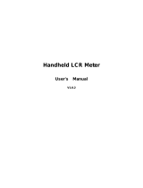
3.1 Description of the controls and elements.
Figure 1.- MZ-505C, front panel.
1. LCD display.
2.
Power ON/OFF button.

INSTRUCTION MANUAL. MZ-505C
Page 10 04/2015
3. Scale button.
4.
Standby button and data on the backlight.
5.
Mode Selection button on.
6.
Test button frequency selection.
7.
Button Parallel or Serial selection.
8.
Resistance function selection button, Capacity and
Inductance.
9.
Selection button Q/D/R.
10.
Read-button preset selection Max, Min and Average.
11.
Adjustment Button.
12.
Adjustment knob upper and lower limits.
13.
Tolerance selection button.
14. Input terminals and sockets.
15. RS-232 Output optocoupler.
16. 12V DC input connector. External power supply.
17. Optic interface.

INSTRUCTION MANUAL. MZ-505C
04/2015 Page 11
3.2 LCD Display illustration
Figure 2.- LCD Display.
. APO On AutoShutdown indicator. 1
2. RS232 indicator.
3. Record mode indicator.
Δ
Mode indicator on.
4.
5. MAX Maximum reading indicator.
6. TOL Tolerance mode indicator.
7. MIN Minimum reading indicator.
8. AVG Average reading indicator.
9. R Indicator of resistance in series or parallel.

INSTRUCTION MANUAL. MZ-505C
Page 12 04/2015
10. Q Quality factor indicator.
11. D Dissipation factor indicator.
12. SER Series mode indicator.
13. PAL Parallel mode indicator.
14.
8888
Secondary display.
15. % Tolerance (percentage) indicator.
16. KM
Ω
Resistance (M
Ω
/ k
Ω
/
Ω
) indicator.
17. 1kHz Frequency indicator.
18. 120Hz Frequency indicator.
19.
Beeper tone indicator for tolerance mode.
20. KM
Ω
Resistance (M
Ω
/ k
Ω
/
Ω
) indicator.
21.
μ
mH Inductance (
μ
H / mH, H) indicator.
22. n
μ
npF Capacitance (pF /
μ
F / mF / F) indicator.
23. AUTO Auto-ranging indicator.
24.
Indicator data retention.
25. SET Mode Indicator Set.
26. LCR L=inductance, C=capacitance or R=resistance
function indicator.
27.
Indicator of high tolerance limits.
28.
Indicator of low tolerance limits.
29.
: Low battery indicator.
/