ESAB Origo™Feed 30-2 User manual
- Category
- Welding System
- Type
- User manual
This manual is also suitable for

0740 800 168 Valid for serial no. 418-xxx-xxxx to 620-xxx-xxxx090506
Feed L302
Feed L304
Origot
OrigoFeed 30-2, OrigoFeed 30-4
Service manual

S0740 800 168/E090506/P26
- 2 -TOCe
Rights reserved to alter specifications without notice.
READ THIS FIRST 3. . . . . . . . . . . . . . . . . . . . . . . . . . . . . . . . . . . . . . . . . . . . . . . . . . . . . . . . . . . . . . . . .
INTRODUCTION 3. . . . . . . . . . . . . . . . . . . . . . . . . . . . . . . . . . . . . . . . . . . . . . . . . . . . . . . . . . . . . . . . . . .
TECHNICAL DATA 4. . . . . . . . . . . . . . . . . . . . . . . . . . . . . . . . . . . . . . . . . . . . . . . . . . . . . . . . . . . . . . . . .
WIRING DIAGRAM 5. . . . . . . . . . . . . . . . . . . . . . . . . . . . . . . . . . . . . . . . . . . . . . . . . . . . . . . . . . . . . . . . .
Component description 5. . . . . . . . . . . . . . . . . . . . . . . . . . . . . . . . . . . . . . . . . . . . . . . . . . . . . . . . . .
OrigoFeed 30-4
Valid for ser.no. 418- and 435-xxx-xxxx 6. . . . . . . . . . . . . . . . . . . . . . . . . . . . . . . . . . . . . . . . . . .
OrigoFeed 30-4, Feed L304
Valid for ser.no. 533-, 620-xxx-xxxx 7. . . . . . . . . . . . . . . . . . . . . . . . . . . . . . . . . . . . . . . . . . . . . . .
OrigoFeed 30-2, Feed L302
Valid for ser.no. 435-, 533-, 620-xxx-xxxx 8. . . . . . . . . . . . . . . . . . . . . . . . . . . . . . . . . . . . . . . . . .
DESCRIPTION OF OPERATION 9. . . . . . . . . . . . . . . . . . . . . . . . . . . . . . . . . . . . . . . . . . . . . . . . . . . . .
13AP1 Control board 0349 304 491 9. . . . . . . . . . . . . . . . . . . . . . . . . . . . . . . . . . . . . . . . . . . . . . .
13AP1:1a Power supply 9. . . . . . . . . . . . . . . . . . . . . . . . . . . . . . . . . . . . . . . . . . . . . . . . . . . . . . . . . . .
13AP1:2a Activation, contactor 9. . . . . . . . . . . . . . . . . . . . . . . . . . . . . . . . . . . . . . . . . . . . . . . . . . . . .
13AP1:3a Wire feed speed 10. . . . . . . . . . . . . . . . . . . . . . . . . . . . . . . . . . . . . . . . . . . . . . . . . . . . . . . .
13AP1:4a Start / Stop 10. . . . . . . . . . . . . . . . . . . . . . . . . . . . . . . . . . . . . . . . . . . . . . . . . . . . . . . . . . . .
13AP1:5a Mode selector switch 10. . . . . . . . . . . . . . . . . . . . . . . . . . . . . . . . . . . . . . . . . . . . . . . . . . . .
13AP1:6a Creep start 11. . . . . . . . . . . . . . . . . . . . . . . . . . . . . . . . . . . . . . . . . . . . . . . . . . . . . . . . . . . . .
13AP1:7a Current relay 12. . . . . . . . . . . . . . . . . . . . . . . . . . . . . . . . . . . . . . . . . . . . . . . . . . . . . . . . . . .
13AP1:8a Burn-back time 12. . . . . . . . . . . . . . . . . . . . . . . . . . . . . . . . . . . . . . . . . . . . . . . . . . . . . . . . .
13AP1:9a Gas valve 12. . . . . . . . . . . . . . . . . . . . . . . . . . . . . . . . . . . . . . . . . . . . . . . . . . . . . . . . . . . . . .
13AP1:10a Motor driving / braking 13. . . . . . . . . . . . . . . . . . . . . . . . . . . . . . . . . . . . . . . . . . . . . . . . . .
13AP1 Component positions 14. . . . . . . . . . . . . . . . . . . . . . . . . . . . . . . . . . . . . . . . . . . . . . . . . . . .
13AP1 Control board 0487 254 880 15. . . . . . . . . . . . . . . . . . . . . . . . . . . . . . . . . . . . . . . . . . . . . . .
13AP1:1b Power supply 15. . . . . . . . . . . . . . . . . . . . . . . . . . . . . . . . . . . . . . . . . . . . . . . . . . . . . . . . . . .
13AP1:2b Activation, contactor 15. . . . . . . . . . . . . . . . . . . . . . . . . . . . . . . . . . . . . . . . . . . . . . . . . . . . .
13AP1:3b Wire feed speed 16. . . . . . . . . . . . . . . . . . . . . . . . . . . . . . . . . . . . . . . . . . . . . . . . . . . . . . . .
13AP1:4b Start / Stop 16. . . . . . . . . . . . . . . . . . . . . . . . . . . . . . . . . . . . . . . . . . . . . . . . . . . . . . . . . . . .
13AP1:5b Mode selector switch 16. . . . . . . . . . . . . . . . . . . . . . . . . . . . . . . . . . . . . . . . . . . . . . . . . . . .
13AP1:6b Creep start 18. . . . . . . . . . . . . . . . . . . . . . . . . . . . . . . . . . . . . . . . . . . . . . . . . . . . . . . . . . . . .
13AP1:7b Current relay 18. . . . . . . . . . . . . . . . . . . . . . . . . . . . . . . . . . . . . . . . . . . . . . . . . . . . . . . . . . .
13AP1:8b Burn-back time 18. . . . . . . . . . . . . . . . . . . . . . . . . . . . . . . . . . . . . . . . . . . . . . . . . . . . . . . . .
13AP1:9b Gas valve 18. . . . . . . . . . . . . . . . . . . . . . . . . . . . . . . . . . . . . . . . . . . . . . . . . . . . . . . . . . . . . .
13AP1:10b Motor driving / braking 19. . . . . . . . . . . . . . . . . . . . . . . . . . . . . . . . . . . . . . . . . . . . . . . . . .
13AP1 Component positions 20. . . . . . . . . . . . . . . . . . . . . . . . . . . . . . . . . . . . . . . . . . . . . . . . . . . .
SERVICE INSTRUCTIONS 21. . . . . . . . . . . . . . . . . . . . . . . . . . . . . . . . . . . . . . . . . . . . . . . . . . . . . . . . . .
What is ESD? 21. . . . . . . . . . . . . . . . . . . . . . . . . . . . . . . . . . . . . . . . . . . . . . . . . . . . . . . . . . . . . . . . . . .
INSTRUCTIONS 22. . . . . . . . . . . . . . . . . . . . . . . . . . . . . . . . . . . . . . . . . . . . . . . . . . . . . . . . . . . . . . . . . . .
SAFETY 22. . . . . . . . . . . . . . . . . . . . . . . . . . . . . . . . . . . . . . . . . . . . . . . . . . . . . . . . . . . . . . . . . . . . . . . .
Lifting instructions 22. . . . . . . . . . . . . . . . . . . . . . . . . . . . . . . . . . . . . . . . . . . . . . . . . . . . . . . . . . . . . .
OPERATION 22. . . . . . . . . . . . . . . . . . . . . . . . . . . . . . . . . . . . . . . . . . . . . . . . . . . . . . . . . . . . . . . . . . . .
Connecting control cable 22. . . . . . . . . . . . . . . . . . . . . . . . . . . . . . . . . . . . . . . . . . . . . . . . . . . . . . . .
Feed L302, connections and control devices 23. . . . . . . . . . . . . . . . . . . . . . . . . . . . . . . . . . . . . .
Feed L304, connections and control devices 23. . . . . . . . . . . . . . . . . . . . . . . . . . . . . . . . . . . . . .
Setting the wire feed pressure 24. . . . . . . . . . . . . . . . . . . . . . . . . . . . . . . . . . . . . . . . . . . . . . . . . . .
MAINTENANCE 24. . . . . . . . . . . . . . . . . . . . . . . . . . . . . . . . . . . . . . . . . . . . . . . . . . . . . . . . . . . . . . . . .
SPARE PARTS 25. . . . . . . . . . . . . . . . . . . . . . . . . . . . . . . . . . . . . . . . . . . . . . . . . . . . . . . . . . . . . . . . . . . .

S0740 800 168/E090506/P26
- 3 -
cm38bd_1
READ THIS FIRST
Maintenance and repair work should be performed by an experienced person, and
electrical work only by a trained electrician. Use only recommended replacement parts.
This service manual is intended for use by technicians with electrical/electronic training for
help in connection with fault-tracing and repair.
Use the wiring diagram as a form of index for the description of operation. The circuit
board is divided into numbered blocks, which are described individually in more detail in
the description of operation. All component names in the wiring diagram are listed in the
component description.
This manual contains details of all design changes that have been made up to and
including April 2009.
The manual is valid for:
OrigoFeed 30-2 and OrigoFeed 30-4 with serial no. 418-xxx-xxxx, 435-xxx-xxxx,
533-xxx-xxxx.
Feed L302
and Feed L304 with serial no. 620-xxx-xxxx.
The OrigoFeed 30-2, OrigoFeed 30-4, Feed L302 and Feed L304 are designed and
tested in accordance with international and European standards IEC/EN 60974.
On completion of service or repair work, it is the responsibility of the person(s)
performing the work to ensure that the product still complies with the requirements of
the above standards.
INTRODUCTION
The wire feeders are renamed:
New name Old name
Origo Feed L302, M08 OrigoFeed 30-2
Origo Feed L304, M09 OrigoFeed 30-4
The wire feed units are intended for MIG/MAG welding with the OrigoMig 405 and Mig L405
power sources.
The feed units can be used with wire on ESAB's MarathonPac, or on wire bobbin Ø 300
mm.
They can be installed either at the power source, suspended above the workposition, on a
support arm or on the floor with or without a wheel set.

S0740 800 168/E090506/P26
- 4 -
cm38bd_1
TECHNICAL DATA
Feed L302 Feed L304
Power supply 42 V 50-60 Hz 42 V 50-60 Hz
Power requirement 150 VA 150 VA
Motor current I
max
3.5 A 3.5 A
Settings data
Wire feed speed
Burnback time
Spot welding time
1.5-22.0 m/min
0-0.7 s
-
1.5-22.0 m/min
0-0.7 s
0.2-5 s
Welding gun connection EURO EURO
Max. diameter wire bobbin 300 mm 300 mm
Wire dimension
Fe
Ss
Al
Cored wire
0.6-1.2 mm
0.6-1.2 mm
1.0-1.2 mm
0.8-1.2 mm
0.6-1.6 mm
0.6-1.2 mm
1.0-1.6 mm
0.8-1.6 mm
Weight 12.6 kg 13.2 kg
Dimensions (l x w x h) 569 x 259 x 355 mm 569 x 259 x 355 mm
Shielding gas
max pressure
Gases for MIG/MAG welding
5 bar
Gases for MIG/MAG welding
5 bar
Maximum permissible load at
60% duty cycle
100% duty cycle
365 A
280 A
365 A
280 A
Enclosure class
basic version
with sealed bobbin holder*
with MarathonPac
IP2X
IP23
IP23
IP2X
IP23
IP23
* Accessory
Enclosure class
The IP code indicates the enclosure class, i. e. the degree of protection against penetration by solid
objects or water. Apparatus marked IP2X are intended for indoor use.
Enclosure class
The IP code indicates the enclosure class, i. e. the degree of protection against penetration by solid
objects or water. Equipment marked IP23 is designed for indoor and outdoor use.
Duty cycle
The duty cycle refers to the time as a percentage of a ten-minute period that you can weld at a cer
tain load without overloading. The duty cycle is valid for 40° C.

S0740 800 168/E090506/P26
- 5 -
cm38bd_1
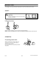
WIRING DIAGRAM
Component description
CAUTION !
STATIC ELECTRICITY can damage circuit
boards and electronic components.
S Observe precautions for handling electrostatic-
sensitive devices.
S Use proper static-proof bags and boxes.
ESD
This component description refers to the wiring diagram. There is a more detailed
description of the components and their function in the description of operation on page 15.
13AP1 Main circuit board with control electronics.
13C1, 13C2 Capacitor 0.1 μF, decoupling.
13M1 Motor.
13RP1 Potentiometer, 2.2 kΩ, for setting the wire feed speed.
13RP2 Potentiometer, 100 kΩ, for setting the burn-back time.
13RP3 Potentiometer, 100 kΩ, for setting the spot welding time.
13SA1 2/4-stroke, spot welding, inching and gas purging change-over switch.
13SA2 Switch, creep start ON/OFF.
13XP2 Terminal for welding current connection from the power source.
13XS . . Connectors with the designation 13XS . . are socket connectors.
13XS12
15-pole panel socket, for connection to the welding power source.
13YV1 Gas valve.

S0740 800 168/E090506/P26
- 6 -
cm38bd_1
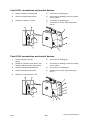
OrigoFeed 30-4
Valid for ser.no. 418- and 435-xxx-xxxx

S0740 800 168/E090506/P26
- 7 -
cm38bd_1
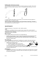
OrigoFeed 30-4, Feed L304
Valid for ser.no. 533-, 620-xxx-xxxx

S0740 800 168/E090506/P26
- 8 -
cm38bd_1
OrigoFeed 30-2, Feed L302
Valid for ser.no. 435-, 533-, 620-xxx-xxxx

Valid for OrigoFeed 30-4 with serial no. 418- and 435-xxx-xxxx
S0740 800 168/E090506/P26
- 9 -
cm38bd_13ap1a
DESCRIPTION OF OPERATION
13AP1 Control board 0349 304 491
This description is valid for control board 0349 304 491, which is fitted in OrigoFeed 30-4
with serial no. 418-xxx-xxxx and 435-xxx-xxxx.
Sections 13AP1:1a to 13AP1:10a below refer to the wiring diagram on page 6.
13AP1:1a Power supply
The feeder obtains a 42 V supply from the control power supply transformer in
the power source.
42 V AC is used for power supply to the gas solenoid valve and the main
contactor. It is also used for the motor drive circuits: see page 19.
The 42 V is rectified and then reduced to +15 V by resistors R65 - R67 and
zener diodes V30 and V31.
13AP1:2a Activation, contactor
The start signal to the power source is connected to board contact X3.9. The
contactor is energised via triac V22.

Valid for OrigoFeed 30-4 with serial no. 418- and 435-xxx-xxxx
S0740 800 168/E090506/P26
- 10 -
cm38bd_13ap1a
13AP1:3a Wire feed speed
The wire feed speed range is from 1.5 to 22 meters per minute.
Potentiometer R8 is used to adjust the maximum wire feed speed and
potentiometer R1 sets the minimum speed. Adjust R8 first and then R1.
13AP1:4a Start / Stop
The wire feed unit starts when the welding gun switch closes.
13AP1:5a Mode selector switch
2-stroke
When switch 13SA1 is in position 1, all input terminals are open, and the unit
operates in 2-stroke mode. Operating the trigger on the welding gun starts the
motor, opens the gas valve and energises the power unit contactor.
Releasing the trigger stops the motor, de-energises the contactor and closes
the gas valve. If burn-back mode is in operation, welding ceases when the
burn-back time has elapsed.
4-stroke
When switch 13SA1 is in position 2, input terminal X1.8 is connected to +15 V,
and the unit operates in 4-stroke mode. Operating the trigger on the welding
gun opens the gas valve: releasing the trigger then starts the motor and
energises the power source contactor.

Valid for OrigoFeed 30-4 with serial no. 418- and 435-xxx-xxxx
S0740 800 168/E090506/P26
- 11 -
cm38bd_13ap1a
Operating the trigger switch for a second time stops the motor and
de-energises the contactor in the power source: releasing the switch then
closes the gas solenoid valve. If burn-back mode is in operation, welding
ceases when the burn-back time has elapsed.
Spot welding
The start sequence is the same as for the 2-stroke mode.
When the spot welding time has elapsed, the motor stops, the contactor
de-energises and the gas valve closes. If burn-back mode is in operation,
welding ceases when the burn-back time has elapsed.
The welding time can be adjusted by potentiometer 13RP3.
Inching
Pressing the trigger switch, starts the wire feed. The gas valve and contactor
are not activated.
Gas purging
Pressing the trigger switch, opens the gas valve. The wire feed and contactor
are not activated.
13AP1:6a Creep start
Creep start means that the motor runs at 50% of the set speed until the current
relay operates, after which the speed increases to the set speed.
Selector switch 13SA2 selects creep start On/Off. Closing the switch on to the
+15 V supply engages creep start.
The creep start function is disabled during inching.

Valid for OrigoFeed 30-4 with serial no. 418- and 435-xxx-xxxx
S0740 800 168/E090506/P26
- 12 -
cm38bd_13ap1a
13AP1:7a Current relay
The current relay is activated when the welding current exceeds 20 A.
13AP1:8a Burn-back time
The burn-back time is the time from when motor braking starts until the main
contactor in the power source opens. It can be adjusted between 0 and 0.7
seconds by potentiometer 13RP2.
13AP1:9a Gas valve
The gas valve is connected to board contacts X3.7 and X3.8. The valve is
energised via triac V23.

Valid for OrigoFeed 30-4 with serial no. 418- and 435-xxx-xxxx
S0740 800 168/E090506/P26
- 13 -
cm38bd_13ap1a
13AP1:10a Motor driving / braking
Driving
The motor is powered from the 42 V AC supply, which is rectified and
thyristor-controlled. The motor speed is controlled by thyristors V19 and V20.
The voltage across resistor R64 is proportional to the motor current. This is
used as the actual value signal for the wire feed speed.
Braking
When the motor is to brake, thyristor V16 is activated by transistor V13. The
thyristor conducts and short-circuits the motor voltage through resistor R52.

Valid for OrigoFeed 30-4 with serial no. 418- and 435-xxx-xxxx
S0740 800 168/E090506/P26
- 14 -
cm38bd_13ap1a
13AP1 Component positions
Control board 0349 304 491

Valid for Feed L304, Feed L302, OrigoFeed 30-2 and for OrigoFeed 30-4 with
serial no. 533-xxx-xxxx
S0740 800 168/E090506/P26
- 15 -
cm38bd_13ap1b
13AP1 Control board 0487 254 880
This description is valid for control board 0487 254 880, which is fitted in OrigoFeed 30-4
from serial no. 533-xxx-xxxx and all of the OrigoFeed 30-2, Feed L302 and Feed L304.
Sections 13AP1:1b to 13AP1:10b below refer to the wiring diagrams on pages 7 and 8.
13AP1:1b Power supply
The feeder obtains a 42 V supply from the control power supply transformer in
the power source.
42 V AC is used for power supply to the gas solenoid valve and the main
contactor. It is also used for the motor drive circuits: see page 19.
The 42 V is rectified and then reduced to +15 V by resistors R65 - R67 and
zener diodes D30 and D31.
13AP1:2b Activation, contactor
The start signal to the power source is connected to board contact X5.5. The
contactor is energised via triac TRC22.

Valid for Feed L304, Feed L302, OrigoFeed 30-2 and for OrigoFeed 30-4 with
serial no. 533-xxx-xxxx
S0740 800 168/E090506/P26
- 16 -
cm38bd_13ap1b
13AP1:3b Wire feed speed
The wire feed speed range is from 1.5 to 22 meters per minute.
Potentiometer R8 is used to adjust the maximum wire feed speed and
potentiometer R1 sets the minimum speed. Adjust R8 first and then R1.
13AP1:4b Start / Stop
The wire feed unit starts when the welding gun switch closes.
13AP1:5b Mode selector switch
The Feed L302 has two operation modes: 2-stroke or 4-stroke.
The Feed L304 has five operation modes: 2-stroke, 4-stroke, spot welding,
inching or gas purging.
Mode selector switch Feed L302, OrigoFeed 30-2
Mode selector switch Feed L304, OrigoFeed 30-4

Valid for Feed L304, Feed L302, OrigoFeed 30-2 and for OrigoFeed 30-4 with
serial no. 533-xxx-xxxx
S0740 800 168/E090506/P26
- 17 -
cm38bd_13ap1b
2-stroke
When switch 13SA1 is in position 1, all input terminals are open, and the unit
operates in 2-stroke mode. Operating the trigger on the welding gun starts the
motor, opens the gas valve and energises the power unit contactor.
Releasing the trigger stops the motor, de-energises the contactor and closes
the gas valve. If burn-back mode is in operation, welding ceases when the
burn-back time has elapsed.
4-stroke
When switch 13SA1 is in position 2, input terminal X1.1 is connected to +15 V,
and the unit operates in 4-stroke mode. Operating the trigger on the welding
gun opens the gas valve: releasing the trigger then starts the motor and
energises the power source contactor.
Operating the trigger switch for a second time stops the motor and
de-energises the contactor in the power source: releasing the switch then
closes the gas solenoid valve. If burn-back mode is in operation, welding
ceases when the burn-back time has elapsed.
Spot welding
The start sequence is the same as for the 2-stroke mode.
When the spot welding time has elapsed, the motor stops, the contactor
de-energises and the gas valve closes. If burn-back mode is in operation,
welding ceases when the burn-back time has elapsed.
The welding time can be adjusted by potentiometer 13RP3.
Inching
Pressing the trigger switch, starts the wire feed. The gas valve and contactor
are not activated.
Gas purging
Pressing the trigger switch, opens the gas valve. The wire feed and contactor
are not activated.

Valid for Feed L304, Feed L302, OrigoFeed 30-2 and for OrigoFeed 30-4 with
serial no. 533-xxx-xxxx
S0740 800 168/E090506/P26
- 18 -
cm38bd_13ap1b
13AP1:6b Creep start
This function is available only for the Feed L304, OrigoFeed 30-4.
Creep start means that the motor runs at 50% of the set speed until the current
relay operates, after which the speed increases to the set speed.
Selector switch 13SA2 selects creep start On/Off. Closing the switch on to the
+15 V supply, engages creep start.
The creep start function is disabled during inching.
13AP1:7b Current relay
The current relay is fitted only to the Feed L304, OrigoFeed 30-4.
The current relay is activated when the welding current exceeds 20 A.
13AP1:8b Burn-back time
The burn-back time is the time from when motor braking starts until the main
contactor in the power source opens. It can be adjusted between 0 and 0.7
seconds by potentiometer 13RP2.
13AP1:9b Gas valve
The gas valve is connected to board contacts X5.3 and X5.4. The valve is
energised via triac TRC23.

Valid for Feed L304, Feed L302, OrigoFeed 30-2 and for OrigoFeed 30-4 with
serial no. 533-xxx-xxxx
S0740 800 168/E090506/P26
- 19 -
cm38bd_13ap1b
13AP1:10b Motor driving / braking
Driving
The motor is powered from the 42 V AC supply, which is rectified and thyristor-
controlled. The motor speed is controlled by thyristors TY19 and TY20.
The voltage across resistor R64 is proportional to the motor current. This is
used as the actual value signal for the wire feed speed.
Braking
When the motor is to brake, thyristor TY16 is activated by transistor Q38. The
thyristor conducts and short-circuits the motor voltage through resistor R52.

Valid for Feed L304, Feed L302, OrigoFeed 30-2 and for OrigoFeed 30-4 with
serial no. 533-xxx-xxxx
S0740 800 168/E090506/P26
- 20 -
cm38bd_13ap1b
13AP1 Component positions
Control board 0487 254 880
Page is loading ...
Page is loading ...
Page is loading ...
Page is loading ...
Page is loading ...
Page is loading ...
-
 1
1
-
 2
2
-
 3
3
-
 4
4
-
 5
5
-
 6
6
-
 7
7
-
 8
8
-
 9
9
-
 10
10
-
 11
11
-
 12
12
-
 13
13
-
 14
14
-
 15
15
-
 16
16
-
 17
17
-
 18
18
-
 19
19
-
 20
20
-
 21
21
-
 22
22
-
 23
23
-
 24
24
-
 25
25
-
 26
26


ESAB Origo™Feed 30-2 User manual
- Category
- Welding System
- Type
- User manual
- This manual is also suitable for
Ask a question and I''ll find the answer in the document
Finding information in a document is now easier with AI
Related papers
-
ESAB Transmatic 4C User manual
-
-
ESAB Feed 30, Feed 30w User manual
-
ESAB Mig L305, Mig L405 User manual
-
-
-
-
ESAB Origo™Feed 30-2, Origo™Feed 30-4 User manual
-
-
