Page is loading ...

FIREPLACE CHASSIS MODELS
BVC-36YA, BVC-42YA AND BVC-50YA
NATURAL GAS BURNER & LOG
MODULE MODELS
BBM-36N-JHB, BBM-42N-JHB AND
BBM-50N-JHB
PROPANE/LP GAS BURNER & LOG
MODULE MODELS
BBM-36P-JHB, BBM-42P-JHB AND
BBM-50P-JHB
FIREBRICK WALL SYSTEMS MODELS
MKB-36,42,50(SS)(SH)-(R,I)A SERIES
MOSAIC MASONRY™
B-VENT GAS FIREPLACE
WITH ELECTRONIC IGNITION
OWNER’S OPERATION AND
INSTALLATION MANUAL
For more information, visit www.fmiproducts.com
FOR YOUR SAFETY
— Donotstoreorusegasolineoranyotherammable
vapors or liquids in the vicinity of this or any other
appliance.
— WHAT TO DO IF YOU SMELL GAS :
• Donottrytolightanyappliance.
• Donottouchanyelectricalswitch;
• Donotuseanyphoneinyourbuilding.
• Immediatelycallyourgassupplierfromaneighbor’s
phone.Followthegassupplier’sinstructions.
• Ifyoucannotreachyourgassupplier,callthere
department.
— Installationandservicemustbeperformedbyaquali-
edinstaller,serviceagencyorthegassupplier.
INSTALLER:Leavethismanualwiththeappliance.
CONSUMER:Retainthismanualforfuturereference.
WARNING:Iftheinformationintheseinstructions
isnotfollowedexactly,areorexplosionmayresult
causingpropertydamage,personalinjuryordeath.
PFS
®
USC

www.fmiproducts.com
124387-01A2
WARNING: Improper installation, adjustment, al-
teration, service or maintenance can cause injury or
propertydamage.Refertothismanualforcorrectin-
stallation and operational procedures. For assistance
oradditional informationconsult a qualied installer,
service agency or the gas supplier.
NOT FOR USE WITH SOLID FUEL
CHECK LOCAL CODES PRIOR TO INSTALLATION
SAVE THIS BOOK
Thisbookisvaluable.Inadditiontoinstructingyouon
howtoinstallandmaintainyourappliance,italsocon-
tainsinformationthatwillenableyoutoobtainreplace-
mentpartsoroptionalaccessoryitemswhenneeded.
Keepitwithyourotherimportantpapers.
StateofMassachusetts:Theinstallationmustbemade
byalicensedplumberorgastterintheCommonwealth
of Massachusetts.
TABLE OF CONTENTS
Safety .................................................................. 3
Unpacking BBM Series........................................ 4
Introduction .......................................................... 5
Selecting Location ............................................... 6
Product Dimensions ............................................ 7
Pre-installation Preparation ................................. 9
Venting Installation .............................................11
Installation ......................................................... 16
Operation ........................................................... 25
Gas Control Module System.............................. 26
Inspecting Burners............................................. 27
Cleaning and Maintenance ................................ 28
Troubleshooting ................................................. 30
Specications .................................................... 35
Wiring Diagram .................................................. 35
Parts .................................................................. 36
Replacement Parts ............................................ 43
Technical Service............................................... 43
Service Hints ..................................................... 43
Accessories ....................................................... 43
Warranty ..............................................Back Cover

www.fmiproducts.com
124387-01A 3
SAFETY
WARNING: This product con-
tainsand/orgenerateschemicals
knowntotheStateofCalifornia
tocausecancerorbirthdefects
orotherreproductiveharm.
IMPORTANT:Readthisowner’s
manualcarefullyandcompletely
before trying to assemble, op-
erate or service this replace.
Improper use of this replace
cancauseseriousinjuryordeath
from burns, re, explosions,
electrical shock and carbon
monoxidepoisoning.
DANGER:Carbonmonoxide
poisoningmayleadtodeath!
This replace is a vented product. This replace
will not produce any gas leakage into your home
if properly installed. This replace must be
properly installed by a qualied service person.
If this unit is not properly installed by a qualied
service person, gas leakage can occur.
CarbonMonoxidePoisoning: Early signs of
carbon monoxide poisoning resemble the u,
with headaches, dizziness or nausea. If you
have these signs, the replace may not have
been installed properly. Getfreshairatonce!
Have replace inspected and serviced by a
qualied service person. Some people are more
affected by carbon monoxide than others. These
include pregnant women, people with heart or
lung disease or anemia, those under the inu-
ence of alcohol and those at high altitudes.
Propane/LP gas and natural gas are both
odorless. An odor-making agent is added
to each of these gases. The odor helps you
detect a gas leak. However, the odor added
to these gases can fade. Gas may be present
even though no odor exists.
Make certain you read and understand all
warnings. Keep this manual for reference. It
is your guide to safe and proper operation of
this replace.
WARNING: Any change to
thisreplaceoritscontrolscan
bedangerous.
1. This appliance is only for use with the type
of gas indicated on the rating plate. This
appliance is not convertible for use with
other gases unless a certied kit is used.
2. For propane/LP replace, do not place
propane/LP supply tank(s) inside any
structure. Locate propane/LP supply
tank(s) outdoors. To prevent performance
problems, do not use propane/LP fuel tank
of less than 100 lbs. capacity.
3. If you smell gas
• shut off gas supply
• do not try to light any appliance
• do not touch any electrical switch; do not
use any phone in your building
• immediately call your gas supplier from
a neighbor’s phone. Follow the gas
supplier's instructions
• if you cannot reach you gas supplier, call
the re department.
4. Never install the replace
• in a recreational vehicle
• in high trafc areas
• in windy or drafty areas
5. This replace reaches high temperatures.
Keep children and adults away from hot
surfaces to avoid burns or clothing igni-
tion. Fireplace will remain hot for a time
after shutdown. Allow surfaces to cool
before touching.
6. Carefully supervise young children when
they are in the room with replace.
7. A hearth extension is not required with this
appliance. If one is installed, it is for aes-
thetic purposes only and does not have
to meet the standard requirements.
8. Turn replace off and let cool before ser-
vicing or repairing. Only a qualied service
person should install, service or repair
this replace. Have replace inspected
annually by a qualied service person.
9. You must keep control compartments,
burners and circulating air passages clean.
More frequent cleaning may be needed due
to excessive lint and dust from carpeting,

www.fmiproducts.com
124387-01A4
bedding material, etc. Turn off the gas valve
and pilot light before cleaning replace.
10. Have venting system inspected annually by
a qualied service person. If needed, have
venting system cleaned or repaired.
11. Keep the area around your replace clear
of combustible materials, gasoline and
other ammable vapor and liquids. Do
not run replace where these are used or
stored. Do not place items such as clothing
or decorations on or around replace.
12. Do not use this replace to cook food or
burn paper or other objects.
13. Do not use any solid fuels (wood, coal,
paper, cardboard, etc.) in this replace.
Use only the gas type indicated on re-
place nameplate.
14. This appliance, when installed, must be
electrically grounded in accordance with
local codes or, in the absence of local
codes, with the National Electrical Code,
ANSI/NFPA 70.
15. Do not obstruct the ow of combustion
and ventilation air in any way. Provide
adequate clearances around air open-
ings into the combustion chamber along
with adequate accessibility clearance for
servicing and proper operation.
16. Do not install replace directly on carpet-
ing, vinyl tile or any combustible material
other than wood. The replace must set
on a metal or wood panel extending the
full width and depth of the replace.
17. Do not use replace if any part has been
exposed to or under water. Immediately
call a qualied service person to arrange
for replacement of the unit.
18. Do not operate replace if any log is
broken.
19. Do not use a blower insert, heat exchang-
er insert or other accessory not approved
for use with this replace.
20. Provide adequate clearances around air
openings.
SAFETY
Continued
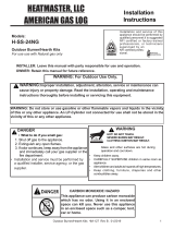
UNPACKING BBM SERIES
CAUTION: Donotremove
dataplatesfrommodule.Data
platescontainimportantwar-
rantyandsafetyinformation.
Note: Unit and all its loose components are
attached to carton tray inside box.
1. Remove entire contents of box using tray
handles (see Figure 1).
2. Set tray on oor and remove oor media
components and remote control.
3. Remove module with log set from tray by
cutting zip ties. Discard tray and foam.
4. Check all items for any shipping damage.
If damaged, promptly inform dealer where
you bought appliance.
Figure 1 - Log Set in Packing Box
Carton Tray
with Handles

www.fmiproducts.com
124387-01A 5
INTRODUCTION
Models BBM-36(N,P)-JHB, BBM-42(N,P)-
JHB and BBM-50(N,P)-JHB are log/gas
burner modules that use an electronic control
valve and ignition system. These modules are
installed into replace chassis models BVC-
36YA, BVC-42YA and BVC-50YA along with
the Mosaic Masonry™ engineered rebrick
wall models MKB-36(H,S)-(I,R)A, MKB-
42(H,S)-(I,R)A and MKB-50(H,S)-(I,R)A. A
FMI PRODUCTS, LLC venting system and
vent cap are not supplied, but are required for
proper operation. If a B-type venting system
is installed, transition pipe model BTC-8 is
required. See venting instructions beginning
on page 11.
WARNING: This gas appli-
ancemustnotbeconnectedto
achimneyueservicingasolid
fuelburningappliance.
BEFORE YOU BEGIN
Before beginning the installation of your re-
place chassis, rebrick walls or module, read
these instructions through completely.
This FMI PRODUCTS, LLC appliance and
its approved components are safe when
installed according to this installation manual
and are operated as recommended by FMI
PRODUCTS, LLC. Unless you use FMI
PRODUCTS, LLC approved components
tested for this appliance, YOU MAY CAUSE
AFIREHAZARD!
The FMI PRODUCTS, LLC warranty will
be voided by and FMI PRODUCTS, LLC
disclaims any responsibility for the following
actions:
A) Modication of the appliance or any of the
components.
B) Use of any component part not approved
by FMI PRODUCTS, LLC in combination
with this appliance.
C) Installation and/or operation in a manner
other than instructed in this manual.
D) The burning of anything other than the
type of gas approved for use in this gas
appliance.
The installation must conform with local
codes or, in the absence of local codes, with
the current National Fuel Gas Code, ANSI
Z223.1/NFPA 54.
WARNING: Installation of this
appliance should be done by a
qualiedserviceperson.
NOTICE: This appliance is not
intendedtobeusedasaprimary
source of heat.
CAUTION: Do not connect
appliancebeforepressuretest-
inggaspiping.Damagetogas
valvemayresultandanunsafe
conditionmaybecaused.
The appliance and it’s individual shutoff valve
must be disconnected from the gas supply
piping system during any pressure testing of
that system at test pressures in excess of 1/2
psig (3.5 kPa).
The appliance must be isolated from the gas
supply piping system by closing its individual
manual shutoff valve during any pressure
testing of the gas supply piping system at
test pressures equal to or less than 1/2 psig
(3.5 kPa).
For the purpose of input adjustment two
pressure taps (for IN and OUT pressures)
are provided on the gas control valve for test
gauge connections to the appliance.

www.fmiproducts.com
124387-01A6
Figure 2 - Possible Locations for
Installing Appliance
INTERNAL WALL
INSTALLATION
CORNER
INSTALLATION
FULL
PROJECTION
INSTALLATION
FLUSH
INSTALLATION
SELECTING LOCATION
To determine the safest and most efcient
location for your appliance, you must take into
consideration the following guidelines:
1. The location must allow for proper clear-
ances (see clearance information on
page 10).
2. Consider a location where heat output
would not be affected by drafts, air con-
ditioning ducts, windows or doors.
3. A location that avoids the cutting of joists
or roof rafters will make installation easier.
Figure 1 shows a plan view of a few com-
mon locations.
Flush installations are recommended where
living space is limited or at a premium and
since the space required to enclose the ap-
pliance would be located beyond an outside
wall, this would also reduce the cutting of
joists, roof rafters and such. Check local
codes for any restrictions.
Projected installations can extend any
distance into the room. A projection may
be ideal for a new addition on an existing,
nished wall.
Corner installations make use of space
that may not normally be used and provides
a wider and more efcient range for radiant
heat transference.
Internalwallinstallations provide a discreet
option for room separation and can also be
ideal as an addition to an existing wall.

www.fmiproducts.com
124387-01A 7
29"
14
1
/
2
"
22
1
/
2
"
26
5
/
8
"
4
1
/
2
"
15
5
/
8
"
4
1
/
2
"
1"
58"
7
1
/
4
"
11"
15
1
/
4
"
3
1
/
2
"
9
1
/
2
"
10
1
/
2
"
67"
61"
49"
11"
7"
30"
1"
45
1
/
8
"
36"
OUTSIDE AIR
ACCESS
GAS LINE
ACCESS
Figure 3 - 36" Model BVC-36YA
PRODUCT DIMENSIONS

www.fmiproducts.com
124387-01A8
PRODUCT DIMENSIONS Continued
22
3
/
4
"
30
1
/
2
"
29"
4
3
/
8
"
15
3
/
4
"
5/8"
17
5
/
8
"
67"
61"
49"
7"
1"
30"
11"
58"
42"
51
1
/
8
"
4
1
/
2
"
3
1
/
2
"
9
1
/
2
"
10
1
/
2
"
8
1
/
2
"
13"
17"
OUTSIDE
AIR
ACCESS
GAS LINE
ACCESS
38
1
/
2
"
28
1
/
2
"
4
3
/
8
"
17
5
/
8
"
19
1
/
4
"
24"
49"
30"
11"
61"
67"
58"
7"
1"
59"
50"
4
1
/
2
"
3
1
/
2
"
9
1
/
2
"
10
1
/
2
"
8
1
/
2
"
13"
17"
GAS LINE
ACCESS
OUTSIDE
AIR
ACCESS
Figure 5 - 50" Model BVC-50YA
Figure 4 - 42" Model BVC-42YA

www.fmiproducts.com
124387-01A 9
Figure 6 - Rough Opening Dimensions
for Installing in a Wall
59
1
/
4
" (50")
58
1
/
8
"
30
1
/
8
"
(42", 50")
28
1
/
4
" (36")
67
1
/
8
"
51
1
/
4
" (42")
45
1
/
4
" (36")
SELECTING LOCATION
To determine the safest and most efcient
location for the replace, you must take into
consideration the following guidelines:
1. The location must allow for proper
clearances (see Figures 6 and 7).
2. Consider a location where replace will
not be affected by drafts, air conditioning
ducts, windows or doors.
3. A location that avoids cutting of joists or
roof rafters will make installation easier.
4. An outside air kit is available with this
replace (see Optional Outside Air Kit,
page 10).
MINIMUM CLEARANCE TO
COMBUSTIBLES
Back and sides of replace 1
1
/
2
" min.*
Front of replace 48" min.
Floor** 0" min.
Perpendicular wall to opening 12" min.
Top spacers 0" min.
Mantel clearances
see Mantels, page 10
Chimney outer pipe surface 1" min.
* Not required at nailing anges
** See step 2 of Framing
WARNING:Donotpackre-
quiredairspaceswithinsulation
orothermaterials.
FRAMING
1. Frame opening for replace using dimen-
sions shown in Figures 6 and 7.
2. If replace is to be installed directly on
carpeting, tile (other than ceramic) or any
combustible material other than wood
ooring, replace must be installed upon
a metal or wood panel extending full width
and depth of replace.
3. Set replace directly in front of this open-
ing and slide unit back until nailing anges
touch side framing.
4. Check level of the replace and shim with
sheet metal if necessary.
PRE INSTALLATION PREPARATION
71" (50" Models)
100" (50" Models)
65" (42" Models)
92" (42" Models)
86.5" (36" Models)
61" (36" Models)
Maintain 1
1
/2"
Clearance
at Sides and
Back of Fireplace
1
1
/2" Clearance
Not Required at
Nailing Flanges
Figure 7 - Corner Installation

www.fmiproducts.com
124387-01A10
PRE-INSTALLATION PREPARATION
Continued
5. Using screws or nails, secure replace to
framing through anges located on sides
of replace.
WARNING: When nishing
appliance,donotoverlapcom-
bustiblematerialontotheblack
front face. Brick, tile or other
noncombustiblematerialsmay
beappliedtothefaceprovided
thatanygapisbetweenthemate-
rialusedandthefaceiscaulked
withanoncombustiblecaulking.
3" (7.6 cm)
1
1
/
2
"
(3.8 cm) Max.
8"
6" (15.2 cm)
14"
12"
(22.9 cm)
Combustible
Materials
30°
Figure 9 - Mantel Clearances - Side View
(Cross Section)
Figure 8 - Outside Air Kit
Secure to Collars with Metal Tape, Screws
or Straps (Min. of 1/4" x 20" in size)
Air Inlet
Location
Must Allow
For Bushes
or Snow
Vent Hood
Required for
Wall Installation
Air Inlet
Eyebrow
Vented Crawl Space
(Check Local Codes
Before Installing in a
Vented Crawl Space)
OPTIONAL OUTSIDE AIR KIT
(MODEL AK4/AK4F)
Installation of an outside air kit should be
performed during rough framing of replace
due to the nature of it's location. Outside com-
bustion air is accessed through a vented crawl
space (AK4F) or through a sidewall (AK4).
CAUTION: Combustion air
inlet ducts shall not terminate
in attic space.
The maximum height for the
air vent can not exceed 3 feet
belowtheuegasoutletofthe
termination.
MANTELS
A combustible mantle shelf maybe installed
a maximum 12" (22.9 cm) from the wall.
Figure 9 and Figure 10 on page 11 show the
minimum allowable distances from various
combustible mantle components in relation
to the fireplace opening.

www.fmiproducts.com
124387-01A 11
VENTING INSTALLATION
A FMI PRODUCTS, LLC or an 8" B-type vent-
ing system must be connected to appliance for
venting to the outside of building. Transition
pipe model BTC-8 is required for use with
B-type venting.
Standing codes requirements concerning
vent installations may vary within your state,
province or local codes jurisdiction. Therefore,
it is recommended that you check with your
local building codes for specic requirements
or in absence of local codes, follow Section
7.0 of the current National Fuel Gas Code
ANSI Z223.1/NFPA 54.
This gas appliance must be vented to the
outdoors only and may not be terminated into
an attic space or into a chimney ue servicing
a solid-fuel burning appliance.
Vent terminations must be located in ac-
cordance with height and proximity rules of
NFPA No. 54. These rules apply to vents at
12" diameter or less and require a minimum
height in accordance with the roof pitch and a
minimum of 8 ft. distance from a vertical wall
or obstruction (see Figure 11).
WARNING: This appliance
must be properly connected
to a system and must not be
connected to a chimney ue
servicing a separate solid fuel
burningappliance.
Lowest
Discharge
Opening
Listed
Vent Cap
8 Ft. Min.
Roof Pitch x/12
Listed Clearance
12
x
Listed
Gas
Vent
H (Min)
Height
From Roof
Figure 11 - Typical Terminations
Roof Pitch
H (Min.)
Feet Meter
Flat to 6/12 1.0 0.30
6/12 to 7/12 1.25 0.38
Over 7/12 to 8/12 1.5 0.46
Over 8/12 to 9/12 2.0 0.61
Over 9/12 to 10/12 2.5 0.76
Over 10/12 to 11/12 3.25 0.99
Over 11/12 to 12/12 4.0 1.22
Over 12/12 to 14/12 5.0 1.52
Over 14/12 to 16/12 6.0 1.83
Over 16/12 to 18/12 7.0 2.13
Over 18/12 to 20/12 7.5 2.27
Over 20/12 to 21/12 8.0 2.44
1
1
/
2
"
(3.8 cm)
Max.
3" (7.6 cm)
Max.
6" (15.2 cm)
Max.
9"
(22.9 cm)
12"
(30.5 cm)
Outer
Surround
Combustible
Material May
Be Used
TOP VIEW
SAFE
ZONE
Perpendicular
Wall
33°
Figure 10 - Side Clearances - Top View (Cross Section)
PRE INSTALLATION PREPARATION
Continued

www.fmiproducts.com
124387-01A12
Figure 12 - Typical Residential Installations
VENTING INSTALLATION
Continued
VENTING INSTALLATION USING FMI
PRODUCTS,LLCVENTINGSYSTEM
FMI PRODUCTS, LLC chimney system
consists of 12", 18", 24", 36" and 48" snap-
lock, double-wall pipe segments, planned
for maximum adaptability to individual site
requirements.
WARNING: The opening in
collararoundchimneyattopof
replacemustnotbeobstructed.
Neveruseblowninsulationtoll
chimneyenclosure.
Figure 13 - Chimney Pipes and Accessories
Hemmed
End
8" Stainless
Inner Pipe
12
3
/
8
"
Galvanized
Outer Pipe
PART NO. DESCRIPTION
12-8DM Pipe Section
18-8DM Pipe Section
24-8DM Pipe Section
36-8DM Pipe Section
48-8DM Pipe Section
RT-8DM Round Termination
RTL-8DM Round Termination
RTT-8DM
Round Termination with Slip
Section
RTTL-8DM
Round Termination with Slip
Section
ET-8DM Square Chase-Top
ETO-8DM Square Chase-Top with Mesh
ETL-8DM
Square Chase-Top with Slip
Section
ETLO-8DM
Square Chase-Top with Mesh &
Slip Section
60E-8DM 60° Offset and Return
EFFECTIVE HEIGHT
OF TERMINATION CAP
UP TO
6 FT. MAX.
17 FT.
MINIMUM
HEIGHT
3 FT. MINIMUM
TO OFFSET
12 FT.
MINIMUM
HEIGHT

www.fmiproducts.com
124387-01A 13
VENTING INSTALLATION
Continued
ASSEMBLY AND INSTALLATION OF
DOUBLE WALL CHIMNEY SYSTEM
Each double wall chimney section consists of
a galvanized outer pipe, a stainless steel in-
ner ue pipe and a wire spacer. Pipe sections
must be assembled independently as chimney
is installed. When connecting chimney directly
to replace, inner ue pipe section must be
installed rst with lanced side up. Outer pipe
section can then be installed over ue pipe
section with hemmed end up. Press down
on each pipe section until lances securely
engage hem on replace starter. The wire
will assure proper spacing between inner and
outer pipe sections.
Opening in collar around
chimneyattopofreplacemust
not be obstructed. Never use
blowninsulationtollchimney
enclosure.
Continue to assemble chimney sections as
outlined, making sure that both inner and outer
pipe sections are locked together. When install-
ing double wall snap-lock chimney together, it
is important to assure joint between chimney
sections is locked. Check by pulling chimney
upward after locking. Chimney will not come
apart if properly locked. It is not necessary to
add screws to keep chimney together.
FIRESTOPSPACERS(V3600FS-8DM)
Firestop spacers are required at each point
where chimney penetrates a floor space.
Their purpose is to establish and maintain
required clearance between chimney and
combustible materials. When pipe passes
through a framed opening into a living space
above, restop must be placed onto ceiling
from below as shown in Figure 14.
Figure 14 - Firestop Spacer with Living
Space Above Ceiling
Figure 15 - Firestop Spacer with Attic
Space Above Ceiling
If area above is a living space, install
restop below framed hole.
If area above is an attic or insulated area,
install restop above framed hole.
They also provide complete separation from
one oor space to another or attic space as
required by most codes. When double wall
pipe passes through a framed opening into
an attic space, restop must be placed into
an attic oor as shown in Figure 15.

www.fmiproducts.com
124387-01A14
VENTING INSTALLATION
Continued
Pitch Slope Opening
"A"Max.
Used Flashing
Model No.
Flat 0° 15" V6F-8DM
0-6/12 26.6° 16
1
/
8
" V6F-8DM
6/12- 12/12 45.0° 20
3
/
8
" V12F-8DM
FLASHINGINSTALLATION(V6F-8DM
ORV12F-8DM)
Determine ashing to be used with roof open-
ing chart. Slide ashing over pipe until base is
at against roof. Replace as many shingles as
needed to cover exposed area and ashing
base. Secure in position by nailing through
shingles (see Figure 17). DO NOT NAIL
THROUGH FLASHING CONE.
Figure 16 - Roof Opening Measurements
PENETRATING ROOF
To maintain a 1" clearance to pipe on a roof
with a pitch, a rectangular opening must
be cut.
1. Determine center point where pipe will
penetrate roof.
2. Determine center point of roof. Pitch is
the distance the roof drops over a given
span, usually 12". A 6/12 pitch means that
the roof drops 6" for each 12" measure
horizontally down from roof rafters.
3. Use roof opening chart (Figure 16) to
determine correct opening length and
ashing required.
4. Remove shingles around opening mea-
sured. Cut out this section.
14
3
/
8
"
(36.5 cm)
30"
(76.2 cm)
1"
(2.5
cm)
1"
(2.5
cm)
Minimum Measurements
1"
(2.5 cm)
Opening "A"
Nail Only
Outer
Perimeter
of Flashing
Storm Collar
Flashing
Cone
Underlap Shingles
at Bottom
Overlap
Shingles Top
and Sides Only
Figure 17 - Flashing Installation
Installing Flashing on a Metal Roof
When installing ashing on a metal roof, it
is required that putty tape be used between
ashing and roof. Flashing must be secured
to roof using #8 x 3/4" screws and then sealed
with roof coating to prevent leakage through
screw holes. A roof coating must also be ap-
plied around perimeter of ashing to provide
a proper seal.
StormCollarInstallation(SC1)
Place storm collar over pipe and slide down
until it is snug against open edge of ash-
ing (see Figure 18). Apply waterproof caulk
around perimeter of collar to provide a proper
seal.
Figure 18 - Storm Collar
Chimney
Pipe
Waterproof
Caulk
Storm
Collar
Flashing

www.fmiproducts.com
124387-01A 15
Terminations/SparkArrestor
Fireplace system must be terminated with
listed round top or chase terminations. In any
case, refer to installation instructions supplied
with termination. Terminations approved for
this replace are RT-8DM and RTL-8DM that
can be used for ashing or chase and ET-
8DM, ETO-8DM, ETL-8DM and ETLO-8DM
for chase style termination only. Figure 19
shows an RTL-8DM round top termination.
CAUTION: Do not seal open-
ingsontherooftopashing.Fol-
lowtheinstallationinstructions
provided with the termination
beingused.
Terminations with 16" slip pipe sections are
available. RTT-8DM and RTTL-8DM are
approved for flashing installations. When
needed, these adjustable terminations may
be used in combination with pipe assembly
to achieve correct chimney height.
Note: In rare instance there is a problem with
side driven rain or wind or chimney is not draft-
ing properly, an ADS-8DM (Anti-Draft Shield)
can be used with round terminations.
VENTING INSTALLATION
Continued
Attach Bracket
Tabs to
Outer Pipe
(3 Places)
Secure with
Screws
RTL-8DM
Level of
Flue Gas
Outlet
Caulk
Collar
Flashing
Underlap Shingles
Bottom Only
Figure 19 - Termination
Overlap
Shingles Top
and Sides
VENTINGINSTALLATIONUSING8"
B-TYPE VENTING SYSTEM
Transition pipe model BTC-8 and starter collar
are shown in Figure 20. Remove starter collar
and set aside. Slide transition pipe over vent
collar and attach with a minimum of 4 screws.
Replace starter collar over transition pipe and
attach using 4 screws located on leg stands.
To install b-vent piping, slide rst piece of
b-vent over transition pipe and attach with
either a minimum of 3 screws or other means
approved by the vent manufacturer.
B-Vent Piping
Transition Pipe
Model BTC-8
Starter Collar
Vent Collar
Figure 20 - Installing Transition Pipe and
Starter Collar
CHECKING FOR PROPER VENTING
After completing and checking electrical, gas
and vent connections, follow the lighting in-
structions and allow the main burner to run for
approximately 5 minutes. Hold a lighted match
near the top edge of replace opening and play
it along entire length of opening (see Figure 21,
page 16). Proper venting should tend to draw
the ame or smoke into the appliance. Improper
venting or escaping of spillage of burned gas, is
indicated when the match ickers or goes out.
If the appliance is found to be improperly
venting, shut it off and notify your installer
or a qualied service agency to inspect the
venting system.
NOTICE: This appliance is
equipped with a vent safety
shutoff switch which will shut
downtheapplianceinthecaseof
aventingproblem.Donotbypass
theventsafetyswitch.Iftheappli-
anceshouldshutdown,contacta
qualiedinstaller,serviceagency
or your gas supplier to have the
ventinspectedbeforeoperating.

www.fmiproducts.com
124387-01A16
Check this area
along entire top
edge of replace
opening. Smoke
or ame should
be drawn into
appliance
opening.
Figure 21 - Checking for Spillage
VENTING INSTALLATION
Continued
FINISHING FIREPLACE
Combustible materials, such as wallboard,
gypsum board, sheet rock, drywall, plywood,
etc. may make direct contact with sides and
top around the replace face. It is important
that combustible materials do not overlap face
itself. Brick, glass, tile or other noncombustible
materials may overlap front face provided
they do not obstruct essential openings such
as louvered slots. When overlapping with
a noncombustible facing material, use only
noncombustible mortar or adhesive.
INSTALLATION
CHECK GAS TYPE
Use proper gas type for the replace unit you
are installing. If you have conicting gas types,
do not install replace. See retailer where you
purchased the replace for proper replace
according to your gas type.
INSTALLING GAS PIPING TO
FIREPLACE LOCATION
WARNING: A qualified
service person must connect
replacetogassupply.Follow
all local codes.
CAUTION: For propane/LP
units,neverconnectreplacedi-
rectly to the propane/LP supply.
Thisheaterrequiresanexternal
regulator (not supplied). Install
theexternalregulatorbetween
the replace and propane/LP
supply.
WARNING: Before you pro-
ceed,makesureyourgassupply
is OFF.
WARNING: For natural
gas,neverconnectreplaceto
private (non-utility) gas wells.
This gas is commonly known
aswellheadgas.
InstallationItemsNeeded
Before installing replace, make sure you
have the items listed below.
• external regulator (supplied by installer)
• piping (check local codes)
• sealant (resistant to propane/LP gas)
• equipment shutoff valve *
• test gauge connection *
• sediment trap
• tee joint
• pipe wrench
• approved exible gas line with gas connec-
tor (if allowed by local codes)
* A manual shutoff valve has been included
with log/burner module models BBM-36(N,P)-
JHB, BBM-42(N,P)-JHB and BBM-50(N,P)-
JHB. You may consider installing an extra gas
shutoff valve outside appliance’s enclosure
(check with local codes) where it can be ac-
cessed more conveniently with a key through
a wall as shown in Figure 22, page 17.

www.fmiproducts.com
124387-01A 17
INSTALLATION
Continued
3" Min.
(7.6 cm)
Side Wall
Of Appliance
Incoming
1/2" Gas Line
Permitted by
Local Codes
Sediment Trap
(Not Supplied)
Figure 24 - Sediment Trap
Figure 22 - Manual Shutoff Valve
Installation
Typical Exterior Wall Gas
Shutoff Installation
Key
Extension
Shutoff
Valve
For propane/LP connection only, the installer
must supply an external regulator. The exter-
nal regulator will reduce incoming gas pres-
sure. You must reduce incoming gas pressure
to between 11" and 14" of w.c. pressure. If
you do not reduce incoming gas pressure,
replace regulator damage could occur. Install
external regulator with the vent pointing down
as shown in Figure 23. Pointing the vent down
protects it from freezing rain or sleet.
Figure 23 - External Regulator with Vent
Pointing Down (Propane/LP Only)
Propane/LP
Supply Tank
External Regulator
with Vent Pointing
Down
IMPORTANT: Install main gas valve (equip-
ment shutoff valve) in an accessible location.
The main gas valve is for turning on or shutting
off the gas to the appliance.
CAUTION: Use only new,
black iron or steel pipe. Inter-
nally-tinnedcoppertubingmay
beusedincertainareas.Check
your local codes. Use pipe of
1/2"diameterorgreatertoallow
propergasvolumetoreplace.
Ifpipeistoosmall,undueloss
ofvolumewilloccur.
We recommend that you install a sediment
trap/drip leg in supply line as shown in Figure
24. Locate sediment trap/drip leg where it
is within reach for cleaning. Install in piping
system between fuel supply and replace.
Locate sediment trap/drip leg where trapped
matter is not likely to freeze. A sediment trap
traps moisture and contaminants. This keeps
them from going into replace gas controls. If
sediment trap/drip leg is not installed or is in-
stalled wrong, replace may not run properly.
Check your building codes for any special
requirements for locating equipment shutoff
valve to replace.
Installation must include an equipment shutoff
valve, union and plugged 1/8" NPT tap. Locate
NPT tap within reach for test gauge hook up.
NPT tap must be upstream from replace.
Natural - From
Gas Meter (5.5"
W.C. to 10.5" W.C.
Pressure)
Propane/LP From
External Regulator
(11" W.C. to 14"
W.C. Pressure)

www.fmiproducts.com
124387-01A18
FIREBRICK WALLS
IMPORTANT:Installationofbrick
should be done after the re-
placeisplacedinapermanent
location.
1. The rebox is shipped with the rebrick
wall retaining brackets preinstalled. There
are a total of six (6) brackets. Remove
these brackets before installing any of the
rebrick walls.
2. Place the hearth into the rebox. This
may require two people. The hearth is
wider than the replace opening and will
need to be tilted to get it inside the rebox.
The ash lip needs to be pulled all the way
forward toward the front of the rebox.
3. It is critical the hearth is center in the
replace before installing any of the other
rebrick walls. There are four slots on the
rebox oor. These slots (two on the left
and two on the right) will be visible when
the hearth is center. Cover the hearth with
a piece of cardboard for protection during
the rest of installation of the rebrick walls.
Hearth
Right Face
Slot
Figure 27 - Slots for Firebrick Walls
Figure 26 - Installing Leading Bricks
INSTALLATION
Continued
4. Install the left and right leading bricks.
Set the rebrick wall on the hearth with
the sheet metal side toward the rebox
surround. The bricks will be ush with the
face of the replace. Secure with screws
provided as shown in Figure 26.
Figure 25 - Installing Gas Line
Gas Line
Opening
Equipment
Shutoff Valve
Valve on
Module
Install incoming 1/2" gas line (as permitted
by local codes) through the gas line opening
on left or right side of the replace chassis
(Figure 25). The pipe should extend to around
the middle of the replace in order to be long
enough to connect to the exible gas line
with shut off valve that is supplied with the
log/burner module. Prepare incoming gas
line with teon tape or pipe joint compound.
5. Install the left and right rebrick walls.
There is a bracket with 2 tabs on the
bottom of each rebrick wall. Angle the
wall into the replace opening and into
the slots on the side of the hearth (Figure
27), then tilt the top of the panel toward
the rebox surround.
6. Secure the rebrick wall using 2 of the
retainers provided. The bracket will slip
underneath the metal lip on the top of the
wall and screw into the inner dome of the
replace (Figure 28, page 19).

www.fmiproducts.com
124387-01A 19
Figure 28 - Installing Side Walls
Retaining
Bracket
Leading
Bricks
Right Wall
INSTALLATION
Continued
7. Install the rear rebrick wall last. Place the
wall face side down on the hearth with the
bottom of the wall toward the rear of the
rebox and the top toward the front of the
replace. Tilt the wall up toward the back
of the rebox. Secure with 2 rear retaining
brackets provided (Figure 29).
8. It is recommended that the joints between
all rebrick walls be grouted for a more
nished look, see grouting instructions.
For more information and to watch a how to
video go to www.fmiproducts.com and select
Technical Support.
Figure 29 - Installing Rear Wall
Retaining
Bracket
GROUTING INSTRUCTIONS
Material provided:
Bag of cement
Bag of sand
Material required:
Piping bag
Joints striker
Heavy duty mixing bucket
Sponge or Wet Cloth
1. Moisten brick surface with damp sponge
or spray bottle just prior to application.
When bricks are wet, any excess grout
mixture on bricks will easily wipe off.
2. In a heavy duty mixing bucket, add equal
parts cement and sand. Add enough water
and mix together well using a power drill
with mixing wand attachment to a yogurt
like consistency. Not adding enough water
can lead to grout falling out after burning.
3. The overall length of piping bag should be
about 16". If the bag is longer than 16",
cut it down to size by removing end with
larger opening. This will make the bag
easier to handle.
4. Put grout mixture into piping bag making
sure the smaller opening is downward and
over a moist towel to avoid spilling. Place
a wet towel over the bucket making sure it
is directly on the surface of grout mixture.
This will keep the mixture moist and it will
not dry out before use.
5. Grout all joints where two rebrick walls
come together.
6. Using a trowel, remove excess grout mix-
ture by moving trowel in the direction of
the joint. Grout mixture in the joint should
now be ush with brick surface. If not
enough grout is applied into each space,
grout may fall out after burning.
7. Using a joint striker, smooth out grout line.
Allow72hoursbefore
installinglog/burnermodule.

www.fmiproducts.com
124387-01A20
CONNECTING FIREPLACE TO GAS
SUPPLY
WARNING:Gaslinehookup
should be done by your gas
supplier or a qualied service
person.
CAUTION:Donotkinkex-
iblegasline.
CAUTION:Compoundsused
onthreadedjointsofgaspiping
shallberesistanttotheaction
of Liqueed Petroleum (LP or
propane)andshouldbeapplied
lightlytoensureexcesssealant
does not enter the gas line.
INSTALLATION
Continued
Rating
Plate
Hole for Screen
Rod
Leading Bricks
Figure 30 - Installing Fireplace Screen
INSTALLING SCREEN
1. Slide round end of screen rod into rings at
top of screen. Attach one push-on nut to end
of rod before attaching last ring of screen.
2. Insert the round end screen rod into hole
on the left and right side of smoke shelf
(Figure 30).
3. Mount at end of screen rod with #10 x 5/8"
to center of smoke shelf.
4. Install other screen rod in same manner.
WARNING: All gas piping
andconnectionsmustbetested
forleaksaftertheinstallationis
completed.
After ensuring that gas valve
ison,applyacommercialleak
detection solution to all con-
nectionsandjoints.Ifbubbles
appear, leaks can be detected
and corrected.
Donotuseanopenameforleak
testing and do not operate any
applianceifaleakisdetected.
Complete your gas installation by connecting
incoming gas line with exible gas line at-
tached to the log/burner modu. Secure tightly
with wrench but DO NOT OVERTIGHTEN.
Apply pipe joint sealant lightly to male NPT
threads. This will prevent excess sealant from
going into pipe. Excess sealant in pipe could
result in clogged replace valves.
InstallationItemsNeeded
• 5/16" hex socket wrench or nut-driver
• sealant (resistant to propane/LP gas, not
provided)
1. Route exible gas line supplied with log/
burner module through the large hole on
the rebox bottom to the incoming gas line
(Figure 25, page 18).
2. Attach exible gas line from gas supply to
control valve (see Figure 31, page 24).
3. Check all gas connections for leaks. See
Checking Gas Connections, page 25.
/