www.snapav.com Support: 866.838.5052
EA-MINI-XD-35 Installation Manual
Pg. 13
For IR codes to be programmed into a control system or remote, visit the product page for the EA-MINI-
XD-35 at www.SnapAV.com to download. Follow the control system manufacturer instructions to configure
commands for use.
IR Learning allows control of the amplifier using the re mote for a display or any other remote on a job. After
completing the learning procedure, the same but tons for power toggle, volume up, volume down, mute toggle,
and input toggle on the selected remote will also control these settings for the amplifier.
See the full color IR Learning Guide in the box for setup instructions. Basic instructions are below if the guide
has been misplaced. Download a new copy from the EA-MINI product product page at www.SnapAV.com.
1. Set amplifier dip switch 2 (RUN/LEARN) to the LEARN (DOWN) position. The Status LED will turn from
solid BLUE (RUN mode) to PINK for about 1 second, and then the LED will flash blue. The amplifier is
now in Learning Mode and waiting to learn the first command (power toggle).
2. Press the command button. The LED should turn solid BLUE for one second and then continue flashing.
3. Press the same command button for a second time to confirm it. The LED should turn solid BLUE for
one second, then PINK for 1 second. The command was learned successfully.
4. Repeat steps 2 and 3 for each command. If a RED LED flashes there is an error. Continue learning the
current command. If you forget which command is being learned (1 through 5 from the list above), watch
the blue LED flash and count the number of flashes between each delay. It will flash from one to 5 times,
indicating the current command being learned.
5. After the last command is learned, or if none are received for 20 seconds, the amplifier will revert to
regular operation. Return dip switch 2 to the RUN (UP) position and test the learned commands.
See the IR Learning Guide for more information about error codes and troubleshooting.
11.2.2. IR Control with Programmed Commands
11.2.3. IR Learning
Basic Instructions
R+ R- L+ L-
DIGITAL IN
SUB OUTANALOG IN
RIGHT
1 2 3 4 5
IR IN
IR OUT
+5V GND
RESET
SPEAKER OUTPUTS
STATUS
1
2
LEFT
SWITCHES
100-240V~50/60Hz 1.6A
UP
1 2
3
4
5
CONTROL
DOWN
IR
RECEIVER
RUN
LEARN
MONO
STEREO
FULL
HP 60Hz
IN 1
IN 2
SWITCH POSITION
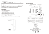
IR Receiver
Switch 2 DOWN to enable IR Learning mode
Switch 1 DOWN for IR Receiver power
Watch the Status LED for feedback
IR RECEIVER (Not
Included) Plugged into
IR IN Port
Command Description
1. Power Toggle Turn amplifier power on and off.
2. Volume Up Turn volume up (louder).
3. Volume Down Turn volume down (quieter).
4. Mute Toggle Toggle mute mode (no volume) on and off.
5. Input Toggle Switch between inputs 1 and 2.
When learning commands, the order of commands programmed will always be the same: