Page is loading ...

2591671 EN 1708
Humidication and Evaporative Cooling
ADDENDUM MANUAL
Adiabatic air humidification/air cooling system
Water Leak Detection Option
for Nortec ME Control
This manual must be read in conjunction with
Nortec ME Control installation manual and operation manual!
READ AND SAVE THESE INSTRUCTIONS

Thank you for choosing Nortec
Installation date (MM/DD/YYYY):
Commissioning date (MM/DD/YYYY):
Location ref.:
Model:
Serial number:
Proprietary Notice
This document and the information disclosed herein are proprietary data of Nortec Humidity Ltd. Neither this do-
cument, nor the information contained herein shall be reproduced, used, or disclosed to others without the written
authorization of Nortec Humidity Ltd., except to the extent required for installation or maintenance of recipient's
equipment.
Liability Notice
Nortec Humidity Ltd. does not accept any liability due to incorrect installation or operation of the equipment or due
to the use of parts/components/equipment that are not authorized by Nortec Humidity Ltd.
Copyright Notice
© Nortec Humidity Ltd., All rights reserved
Technical modications reserved

3Contents
Contents
1 Introduction 4
1.1 Notes on the addendum manual 4
2 For your safety 5
3 System overview / Principle of operation 7
4 Installation work 8
4.1 Installing the leak detection enclosure 8
4.2 Mounting the leak detection sensor board and connecting the sensor cable 11
5 Conguration 14
5.1 Conguration process 14
5.2 Sensor setup 15
5.2.1 Sounder Jumper modes 15
5.2.2 Relay output jumper modes 16
6 Operation 17
6.1 Basic operation 17
6.2 Advanced operation features 18
6.2.1 LED status 18
6.2.2 Adjusting the alarm threshold 19
6.2.3 Error indication 19
7 Spare parts 20

4 Introduction
1 Introduction
1.1 Notes on the addendum manual
This manual is an addendum for the installation of the optional leak detection system for the Nortec ME
Control and must be read in conjunction with the installation manual and operation manual for Nortec
ME Control.
This addendum manual has been written to ensure the safe use, performance and longevity of the
equipment and is intended for use by engineers and properly trained technical personnel. Please read
this manual thoroughly before installing the optional leak detection sensor.
If you have questions after reading this documentation, please contact your Nortec representative.
They will be glad to assist you.
Symbols used in this manual
CAUTION!
The catchword “CAUTION” used in conjunction with the caution symbol in the circle designates notes
in this manual that, if neglected, may cause damage and/or malfunction of the unit or other mate-
rial assets.
WARNING!
The catchword “WARNING” used in conjunction with the general caution symbol designates safety
and danger notes in this manual that, if neglected, may cause injury to persons.
DANGER!
The catchword “DANGER” used in conjunction with the general caution symbol designates safety and
danger notes in this manual that, if neglected, may lead to severe injury or even death of persons.
Safekeeping
Please safeguard this addendum manual in a safe place, where it can be immediately accessed. If the
equipment changes hands, the documentation must be passed on to the new operator.
If the documentation gets misplaced, please contact your Nortec representative.
Language versions
This addendum manual is available in various languages. Please contact your Nortec representative
for information.

5For your safety
2 For your safety
General
Every person working with the leak detection system and the Nortec ME Control must have read and
understood this addendum manual, and the Nortec ME Control installation manual and operation manual,
before carrying out any work.
Knowing and understanding the contents of the manuals is a basic requirement for protecting the person-
nel against any kind of danger, to prevent faulty operation, and to operate the unit safely and correctly.
All ideograms, signs and markings applied to the unit must be observed and kept in readable state.
Qualicationofpersonnel
All work described in this addendum manual may only be carried out by specialists who are well
trainedandadequatelyqualiedandareauthorizedbythecustomer.
For safety and warranty reasons any action beyond the scope of this manual must only be carried out
by personnel with appropriate industry recognised qualications or training.
It is assumed that all persons working with the leak detection system and the Nortec ME Control are
familiar and comply with the appropriate local regulations on work safety and the prevention of accidents.
Intended use
The leak detection system is intended exclusively for the detection of standing water in AHU's or air
ducts, or at the location of hydraulic installation of the Nortec ME Control, and within the speci-
ed operating conditions. Any other type of application, without the written consent of the manufacturer,
is considered as not conforming with the intended purpose and may lead to the Nortec ME Control
becoming dangerous.
Operation of the equipment in the intended manner requires that all the information contained in this
addendum manual as well as in the Nortec ME Control installation manual and operation manual
are observed (in particular the safety instructions).
Danger that may arise from the Nortec ME Control
DANGER!
Risk of electric shock!
The control unit of the Nortec ME Control contains live mains voltage. Live parts may be exposed
when the control unit is open. Touching live parts may cause severe injury or danger to life.
Prevention: Before commencing any work on the leak detection system and the control unit discon-
nect the mains supply voltage to the control unit via the electrical isolator in the mains supply line, and
secure the electrical isolator in “Off” position against inadvertent switching on.

6 For your safety
Safety Reporting
All persons working with the leak detection system are obliged to report any alterations to the system that
may affect safety to the owner without delay and to secure such systems against accidental power-up.
Prohibitedmodicationstotheunit
Nomodicationsmustbeundertaken on the leak detection system without the express written con-
sent of the manufacturer.
For the replacement of defective components use exclusively original accessories and spare parts
available from your Nortec representative.

7System overview / Principle of operation
3 System overview / Principle of operation
The leak detection system consists of the following components:
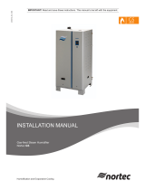
Fig. 1: Overview / Scope of delivery
Principle of Operation
The water leak detection system is designed to indicate when water is pooling inside the AHU where the
Nortec ME Control system is installed, and prevent further ooding from occurring. When water enters
the detection enclosure it bridges a circuit on the cable sensor inside and signals the Nortec ME Control
system to enter fault mode. The indications are an audible alarm from the system PCB and a fault mes-
sage on the display screen of the Nortec ME Control. Depending on the operating mode selected the
system can either be left to continue running, or be disabled with the water inlet valve and drain held
closed in order to minimise the potential for further ooding.
When the fault occurs, a trained engineer must inspect the AHU and installed equipment to ascertain
the source of the fault and correct it.
Important: If a reverse osmosis system is being used to supply the Nortec ME Control with RO water,
a different "RO water leak detection system" must be used in place of this "water leak detection sys-
tem" as the conductivity of RO water is generally too low for this system to detect. Contact your Nortec
distributor for details of the "RO water leak detection system" if required.
Self tapping screw
No.8 x 1.5"
ø0.16" (ø4 mm) ID O-ring
Water sensor enclosure
Water sensor cable
Enclosure washer
Leak detection board
Connecting cable
leak detection board to driver board
Water sensor

8 Installation work
4 Installation work
4.1 Installing the leak detection enclosure
The water sensor enclosure should be placed near to the hydraulic module or tank connection at the
lowest point where water can collect, and xed to the oor of the AHU or other chosen position using
the central xing point of the enclosure. A 0.16" (4 mm) O-ring is provided to form a seal at the top of the
enclosure, the installer should use an appropriate screw or removable xing to ensure that the enclosure
cannot be accidentally moved from the required position.
This leak detection system only supports a single leak detection sensor, if more than one sensor is
required to monitor multiple locations the "RO water leak detection system" which supports multiple
sensors should be used.
Fig. 2: Placement of the sensor enclosure assembly

9Installation work
1. Before the installation of the leak detection enclosure can take place, the user must ensure that the
following actions have been carried out. Refer to the decommissioning section in the Nortec ME
Control operation manual for additional instructions regarding these actions.
• Isolate the water supply (close shut-off valve in the water supply line).
• Drain the tank fully.
• Isolate power supply to the control unit.
2. If the water sensor enclosure is installed in the AHU/Air duct: Run the sensor cable (with the sensor
end of the cable) into the AHU/air duct via a wall feed through equipped with cable glands.
Note: The cable feed through must be done by the customer and must be equipped with cable glands.
3. Assemble the water sensor as shown in the gure below. Ensure the water sensor cable is securely
tted in the water sensor enclosure with the at neoprene enclosure washer in place.
Fig. 3: Assembling the water sensor
4. Place the assembled enclosure at the appropriate position with the washer side downwards. Hold
washer in place while positioning the assembled water sensor enclosure.
Note: Ensure the desired location for the enclosure is clean and dry.
Water sensor enclosure
Water sensor cable
Enclosure washer

10 Installation work
5. Fix the water sensor enclosure to the AHU/building oor:
RecommendedxingforAHU's Recommendedxingforbuildingoor
• Drill a ø0.13" (ø3.2 mm) pilot hole into the
oor of the AHU at the central point of loca-
tion.
• Insert a No.8 x 1.5" self-tapping screw with the
ø0.16" (ø4 mm) O-ring through the centre of
the fully assembled water sensor enclosure
and screw the enclosure tight to the oor of
the AHU.
• Drill at the desired position a hole for a dowel
with the appropriate diameter and depth into
the oor.
• Insert the appropriate dowel into hole, then
insert a No.8 x 1.5" self-tapping screw with the
ø0.16" (ø4 mm) O-ring through the centre of
the fully assembled water sensor enclosure
and screw the enclosure tight to the building
oor.
6. Secure the sensor cable with cable ties at suitable intervals along the cable run to the Nortec ME
control unit.
Note: Ensure sensor cable is placed in such a way that the insulation is not damaged by sharp
edges and so that it does not create a trip hazard or hinder correct maintenance of the components.

11Installation work
4.2 Mounting the leak detection sensor board and connecting the sensor cable
Nortec ME Control systems purchased with the leak detection system will be provided with the leak
detection sensor board already tted.
1. Isolate power to the Nortec ME control unit by switching off the electrical isolator. Secure the electri-
cal isolator in the "Off" position to prevent inadvertant switching on.
2. Remove the front cover of the control unit.
CAUTION!
Electronic components are very sensitive to electrostatic discharge. Before proceeding with the
next step, appropriate measures (ESD-protection) must be taken to prevent damage to electronic
components.
3. Open the control unit inner door.
4. Clip the leak detection board to a space on the DIN rail at the bottom of the internal mounting plate
with the sensor terminals at the bottom and the relay terminals at the top.
Fig. 4: Mounting the leak detection board
5. Unclip the cable trunking covers that surround the driver board and remove from the trunking.
6. Connect the insulated ferrule ends of the driver board to leak detection cable into the appropriate
terminals of terminal block "X12" on the driver board as shown in Fig. 5.

12 Installation work
7. Feed the cable into the closest appropriate gap in the cable trunking and route it around the trunking
channel to exit through another gap at a point near the leak detection sensor board.
8. Install the free ends of the driver board to leak detection cable to the terminals on the leak detection
sensor board as shown in Fig. 5.
9. Lead the sensor cable through the rectangular cable lead-through into the control unit and pull through
all excess from outside.
10. Inside the control unit, install the sensor cable ends into the sensor terminals of the leak detection
sensor board as shown in Fig. 5. Ensure that the blue capacitor component is attached to both ends
of the sensor cable.
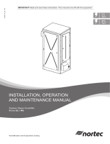
F2 (630 mAT)
X11 X12
X13
24V E
GND
GND
24V E
FQ+
24V P
N FQ2
N FQ1
ERR FQ
GND
NC
Mode
Off
Reset
Latch
On
24V E
24V E
24V E
24V E
LEAK
CS1
LVL DP
GND
NOC
24VSensorGnd
red
white
white
white
white
orange
orange
orange
blue
Water sensor
black
black
black
black
red
red
red
Connecting cable
leak detection board to driver board
Driver board
Water sensor
board
Fig. 5: Wiring diagram

13Installation work
11. Secure any loose sensor cable either in an appropriate section of the trunking or at the bottom of
the control unit with a cable tie.
12. Replace the trunking covers and close the control unit inner door. Replace the front cover and secure
it with the retaining screw.

14 Conguration
5 Conguration
5.1 Congurationprocess
Nortec ME Control systems purchased with the leak detection system will be provided with the leak
detection function already activated.
If the leak detection system is retrotted into an existing Nortec ME Control system, the function must
be activated in the Engineering level of the control software as follows.
Note: This process is only to be carried out by a Nortec engineer or distributor.
For a description of "Active" and "Passive" modes see chapter 6.1.
Enter Engineering
menu password
Select
<Engineering>
Select
<More...>
Select
<Safety Parameter>
Select
<Standing Water>
Switch function from
"Off" to "Active" or
"Passive"andconrm.
Fig. 6: conguration process

15Conguration
5.2 Sensor setup
Important: The alarm system settings have been checked by Nortec and should not require changing.
Any change of settings is done so at the users own risk.
Ensure the power supply is isolated, the isolator is secured in the off position, and suitable electrostatic
discharge protection is used before opening the control panel to change these settings.
Fig. 7: Display and operating element of the leak detection board
5.2.1 Sounder Jumper modes
The default position for this jumper is Active mode. All subsequent instructions in this document that
refer to an audible alarm are based on the jumper remaining in this default position.
Jumper setting Sounder mode Description
Silent If jumper is removed, the sounder is disabled and will remain silent
even if a water leakage is detected.
Active If jumper is set, the sounder is enabled. If a water leakage is de-
tected the sounder is activated and an audible alarm will sound.
LED1
LED4
Green LED
Yellow LED
Orange LED
Red LED
Sensivity trimmer
Reset button
Sounder jumper
Relay mode jumpers

16 Conguration
5.2.2 Relay output jumper modes
The default position for this jumper is Latch mode, if the jumper position is changed the panel may not
report a leak correctly. Do not change this setting unless carrying out a specic test on the system and
always return the jumper to the Latch mode position.
Jumper setting Output mode Description
Off The relay will be de-energised and the sounder silent, no matter
what the sensor condition. The green and yellow LEDs will ash
alternately while in “learning” mode, and then just the green LED
will ash continuously to show that this mode is selected. The other
three LED’s will indicate as normal.
Reset The unit will report all ood alerts by releasing the relay and acti-
vating the sounder (if enabled). Any transition will be reported for
a minimum of two seconds. When the sensor stops indicating a
ood, the unit resets automatically.
Latch In latching (manual reset) mode the unit reports the initial ood alert
by releasing the relay and activating the sounder (if enabled). The
relay and sounder will continue to indicate the alarm until the reset
switch on the unit has been pressed. NB The LED’s will indicate
the true status of the sensor.
On This is a mode used to test the installation without needing to wet
the sensor. The sounder and relay will be energised and the green
and red LEDs will ash alternately for approximately 2 minutes to
show that this mode is selected. After this time, the green LED will
be ON while the red LED will continue to ash.

17Operation
6 Operation
6.1 Basic operation
When the unit is rst powered up, or if the reset button is pressed, the sounder will be activated (if ena-
bled) and the LED’s demonstrated. The relay will be left de-energised for a minimum of two seconds.
Once the relay has been energised, it will be held in this state for a minimum of two seconds, even if a
ood is detected immediately.
During normal operation the relay is energized, if a leak is detected the relay is de-energized and the
control panel reports a leak.
When a leak is detected:
• The Nortec ME Control will enter a fault mode and an audible alarm will sound.
If Active mode has been selected:
• The system will stop operation and no pumps will run.
• The inlet will be held closed so no more water can enter the tank and hydraulic module.
• The drain will also be held closed so that, in case of a drain issue, no more water will be released
from the tank or hydraulic module.
Note: for hygiene reasons, if the leak detection fault has not been cleared within 24 hours the tank
will automatically drain.
If Passive mode has been selected:
• The system will remain in operation and continue with normal cycles.
A trained engineer must inspect the AHU and installed equipment to ascertain the source of the fault
and correct it. Once the leak has been corrected, any standing water cleared and all surfaces dried,
the enclosure should be disassembled and all parts dried thoroughly. The enclosure can then be reas-
sembled and reinstalled in position following the steps in chapter 4.1.
WARNING!
In the event of water carry-over from the evaporative cassettes or a water leak, surfaces near the ME
system may have become wet. This could result in a slipping hazard or an increased risk when handling
components. If this occurs, risk assess the situation and take suitable precautions before working on
the ME system. If carry-over was the cause of any standing water in the AHU/duct, follow the advice
in chapter 7.4 - Malfunctions without indication of the operation manual to remedy the problem.
The fault and audible alarm in the ME Control unit can be reset by cycling the power switch on the right
side of the Nortec ME control unit, once the unit has rebooted normal operation should be resumed.

18 Operation
Alternatively this can be done by pressing the reset button on the sensor board. If opening the panel
for any reason while it is is energized, ensure appropriate measures are in place to safeguard against
electric shock and electrostatic discharge.
DANGER!
Risk of electric shock!
The control unit of the Nortec ME Control contains live mains voltage. Live parts may be exposed
when the control unit is open. Touching live parts may cause severe injury or danger to life.
6.2 Advanced operation features
6.2.1 LED status
If the Alarm does not sound when the sensor is submerged, or sounds continuously when dry, the LEDs
can provide indication of the unit state.
Green LED: The green LED should be on continuously during normal operation, except in the “Off”
mode or there is an error (see chapter 6.2.3).
Yellow LED: This will be on if the sensor reading is more than 33% of the threshold setting.
Orange LED: This will be on if the sensor reading is more than 66% of the threshold setting.
Red LED: This will be on solidly if the sensor reading exceeds the threshold setting. If the red LED is
ashing, it is either because the unit is in “test” mode or, if the green LED is off, because
the unit has discovered an error (see chapter 6.2.3).

19Operation
6.2.2 Adjusting the alarm threshold
The alarm threshold trimmer can be used to raise or lower the sensitivity of the unit.
On power-up or by pressing the reset button, the unit enters “learning” mode. In “learning” mode, the
sensor sensitivity trimmer can be adjusted, which changes the threshold at which the unit will report an
alarm. The unit will only be in “learning” mode for approximately 20 seconds after power-up or reset.
After this time the unit will enter “run” mode, and any adjustment of the trimmer or change to the relay
mode jumper will have no effect.
Note that if the reset button is pressed, the alarm will sound (if enabled) for at least two seconds as
part of the initialisation function. In this event, the mode jumper and trimmer setting should be checked
before the unit is left to monitor the sensor autonomously.
With the sensor is connected and the unit in learning mode, slowly adjust the threshold trimmer. As the
input becomes more sensitive, the yellow, orange and nally red LED’s will progressively light. If the red
LED is lit, the sensitivity is set too high, and the unit is in alarm.
6.2.3 Error indication
If the unit thinks that there is an error (for example, the sensor reads such an extreme level that a short
circuit is suspected) then the red LED will ash continuously, the relay will be de-energised, and the
sounder will be activated (if enabled). The sounder pattern will be three tones followed by a gap, to
differentiate it from the ood warning. The green LED will be off to differentiate between an error report
and the “Test” mode. The error report will be held until the reset button is pressed, although this function
could reset automatically if the unit is in “Reset” mode.

20 Spare parts
Self tapping screw
No.8 x 1.5"
ø0.16" (ø4 mm) ID O-ring
Water sensor enclosure
Water sensor cable
Enclosure washer
Leak detection board
Connecting cable
leak detection board to driver board
Water sensor
7 Spare parts
Fig. 8: Spare parts
Please contact your Nortec representative for spare parts!
Safe disposal of electrical and electronic components
Please dispose of defective parts in accordance with your local recycling laws and regulations.
Waste electrical and electronic equipment may contain hazardous substances, which, if not
treated properly, can be harmful to the environment and human health. Specic treatment of
waste electrical and electronic equipment is therefore essential.
/