Page is loading ...

Owner’s Manual
1111 W. 35th Street, Chicago, IL 60609 USA
www.tripplite.com/support
SmartOnline
™
Rack/Tower On-Line UPS Systems
Copyright © 2011 Tripp Lite. All rights reserved. SmartOnline
™
is a trademark of Tripp Lite.
Warranty
Registration:
register online today for a chance
to win a FREE Tripp Lite product—
www.tripplite.com/warranty
Not suitable for mobile applications.
1. Important Safety Instructions 2
2. Installation 3
2.1 Mounting (Rack) 3
2.2 Mounting (Tower) 4
2.3 Connection and Start-Up 4
2.4 Optional Connections 5
3. Operation 8
3.1 Front Panel Switches 8
3.2 Advanced Operational Settings 8
3.3 Front Panel Indicator Lights 9
3.4 Rear Panel 11
3.5 Communications 12
4. Troubleshooting 13
5. Battery Replacement 14
6. Storage and Service 16
6.1 Storage 16
6.2 Service 16
7. Warranty Registration 17
Español 18
Français 35
Pyññêèé 52
201102139 93-2882.indb 1 3/30/2011 10:04:10 AM

2
1. Important Safety Instructions
UPS Location Warnings
• InstalltheUPSsystemindoors,awayfromexcessmoistureorheat,conductive
contaminants,dustordirectsunlight.
• Forbestperformance,keeptheindoortemperaturebetween32ºFand104ºF
(0ºCand40ºC).
• LeaveadequatespacearoundallsidesoftheUPSsystemforproperventilation.
• DonotmounttheUPSsystemwithitsfrontorrearpanelfacingdown(atanyangle).
MountinginthismannerwillseriouslyinhibittheUPSsystem’sinternalcooling,
eventuallycausingproductdamagenotcoveredunderwarranty.
UPS Connection Warnings
• ConnecttheUPSsystemdirectlytoaproperlygroundedACpoweroutlet.Theoutlet
mustbeinstalledneartheUPSsystemandmustbeeasilyaccessiblefordisconnection.
• Toreducetheriskoffire,connectonlytoacircuitprovidedwith20amperesmaximum
branchcircuitovercurrentprotectioninaccordancewithyourlocalandNational
ElectricalCode(NEC),ANSI/NFPA70.
• DonotmodifytheUPSsystem’splug,anddonotuseanadapterthatwouldeliminate
theUPSsystem’sgroundconnection.DonotplugtheUPSsystemintoitself;thiswill
damagetheUPSsystem.
• DonotuseextensioncordstoconnecttheUPSsystemtoanACoutlet.
• IftheUPSsystemreceivespowerfromamotor-poweredACgenerator,thegenerator
mustprovideclean,filtered,computer-gradeoutput.
Equipment Connection Warnings
• Useofthisequipmentinlifesupportapplicationswherefailureofthisequipmentcan
reasonablybeexpectedtocausethefailureofthelifesupportequipmentorto
significantlyaffectitssafetyoreffectivenessisnotrecommended.Donotusethis
equipmentinthepresenceofaflammableanestheticmixturewithair,oxygenornitrous
oxide.
• DonotconnectsurgesuppressorsorextensioncordstotheoutputoftheUPSsystem.
ThismightdamagetheUPSsystemandmayaffectthesurgesuppressorandUPSsystem
warranties.ConnectingaTrippLitepowerdistributionunit(PDU)totheoutputofthe
UPSsystemissafeandwillnotvoidthewarranty.
Battery Warnings
• RefertoSection 5: Battery Replacementforacompletelistofbatterywarnings.
SAVE THESE INSTRUCTIONS
Thismanualcontainsinstructionsandwarningsthatshouldbefollowedduringthe
installation,operationandstorageofthisproduct.Failuretoheedthesewarningsmay
affectthewarranty.
201102139 93-2882.indb 2 3/30/2011 10:04:10 AM

3
2. Installation
1
Theincludedplasticpegs
A
willsupportthe
emptyrackmountshelves
B
untilthe
permanentmountinghardwareisinstalled.
Insertapegnearthecenterofthefrontand
rearbracketofeachshelfasshown.(Each
frontbrackethas6holesandeachrear
brackethas3holes.)Thepegswillsnapinto
place.
Afterinstallingthepegs,expandeachshelf
tomatchthedepthoftheverticalrackrails.
Thepegswillfitthroughthesquareholesin
therackrailstosupporttheshelves.Confirm
thattheshelvesarelevelinalldirections.
Note: The support ledge of each shelf must
face inward.
2
Securetheshelves
B
totherackrails
permanentlyusingthelongerincluded
screwsandwashers
C
asshown.(Place4
screwsatthefrontand4screwsattheback.)
Tightenallscrewsbeforeproceeding.
Warning: Do not attempt to install the UPS
system until the required screws have been
inserted and tightened. The plastic pegs will
not support the weight of the UPS system.
3
Attachthemountingbrackets
D
tothe
forwardmountingholesoftheUPSsystem
usingtheshorterincludedscrews
E
.The
mountingbracketearsmustfaceforward.
4
Withtheaidofanassistant,lifttheUPS
systemandslideitontothemounting
shelves.Insert4oftheincludedscrews
F
throughthemountingbracketearsandinto
theverticalrackrails.Tightenallscrews
securely.
• UsetheincludedrackmountshelvesandmountinghardwaretomounttheUPSsystemina
4-postrackorrackenclosure.TomounttheUPSsystemina2-post(telecom)rack,order
TrippLite’s2-PostRackmountKit(model2POSTRMKITWM,soldseparately).
• Theinstructionsinthismanualareforcommonrackandrackenclosuretypesandmaynot
beappropriateforallmountingapplications.Theusermustdeterminethefitnessof
hardwareandproceduresbeforemounting.Ifhardwareorproceduresarenotsuitablefor
theapplication,contactthemanufactureroftherackorrackenclosureforasolution.
Warning: The UPS system is very heavy—be careful when moving or lifting it.
4-Post Mounting Procedure
1
2
3
D
D
E
E
4
F
F
2.1 Mounting (Rack)
C
B
C
B
A
B
B
A
201102139 93-2882.indb 3 3/30/2011 10:04:14 AM

4
1
2
2. Installation
(
continued
)
TheUPSsystemcanbemountedinanupright
towerpositionwhenusedwithTrippLite’s
optionalbasestandkit(model2-9USTAND,
soldseparately).WhenmountingtheUPS
systeminatowerposition,makesurethecontrol
panelisclosertothetopofthecabinetthanthe
bottom.
Thecontrolpanelcanberotatedtomatchthe
orientationoftheUPSsystem.Pullthepanel
out,rotateitandpushitbackintoplaceas
shown.
Warning: The UPS system is very heavy—be
careful when moving or lifting it.
1
Plug the UPS system into an
electrical outlet.
Note: The UPS system does not include an
input power cord.
Connectauser-suppliedpowercordtothe
IEC-320-C20inputreceptacle.Thepower
cordshouldhaveanIEC-320-C19connector
ononeendandaplugappropriateforyour
localsite’sutilityoutletontheotherend.
TheUPSsystemmustbeconnectedtoa
dedicatedcircuitofsufficientamperage.
RefertotheUPSsystemnameplateforinput
requirements.
AftertheUPSsystemispluggedin,the
followingsequenceofeventswilloccur:
1. ThefanwillturnonandallLEDswill
illuminatemomentarily.
2. ThepercentlevelLEDs(25%,50%,
75%and100%)willilluminateoneata
time.
3. The“LINE”and“LOAD”LEDswill
illuminatetoindicatenormaloperation.
Note: Power will not be supplied to the
outlets until the UPS system is turned on.
Some models may differ.
1
2.3 Connection and Start-Up
2.2 Mounting (Tower)
Voltage Selection Mode
Pleasefollowbelowproceduretoselecttheoutput
voltagebyfrontpanel.
1. PresstheON/TESTandOFFbuttons
simultaneouslytoenter“VoltageSelection”
mode.ThethreeLEDslabeledVOLTAGE
SELECTIONMODEwillflashwhenyouhave
enteredthismode.
2. PresstheON/TESTbuttontoselecttheoutput
voltagefrom200to240.
3. Afterselectingthedesiredoutputvoltage,press
theON/TESTandOFFbuttonssimultaneously
tosaveyourselectionandexit“Voltage
Selection”mode.
201102139 93-2882.indb 4 3/30/2011 10:04:16 AM

5
2. Installation
(
continued
)
2
3
Some models may differ.
2.3 Connection and Start-Up
(
continued
)
Voltage Note: The UPS system supports a
nominal AC voltage setting of 200V, 208V,
220V, 230V or 240V. 230V is the factory
default setting. The full output capacity of
2,500 watts is available when the UPS
system is set at 230V or 240V. When the
UPS system is set at 200V, 208V or 220V,
output capacity is reduced to 2,400 watts.
The nominal voltage setting can be
changed using the control panel buttons,
with PowerAlert software or the optional
SNMPWEBCARD internal accessory card.
See the PowerAlert software or
SNMPWEBCARD documentation for
more information about changing the
nominal voltage setting.
2
Plug equipment into the UPS
system’s AC outlets.
Note: Use the supplied C13 to C14
interconnection cord.
TheUPSsystemisdesignedtosupport
computerequipmentonly.TheUPSsystem
willbecomeoverloadedifhousehold
appliancesorlaserprintersareconnectedto
its outlets.
Note: Additional interconnection cords
(C13 to C14) are available from Tripp Lite.
Visit www.tripplite.com. (Part # P004-006)
3
Turn the UPS system ON.
ToturnontheUPSsystem,pressthe“ON/
TEST”buttonforapproximately1second
untiltheUPSsystembeeps,thenreleasethe
button.
TheUPSsystemwillbeginprovidingACpowertoits
outlets.The“ONLINE”LEDwillilluminate.
Note: UPS system will function properly upon
initial startup, however, maximum runtime for the
unit’s battery will only be accessible after it has
been charged for 24 hours.
TheUPSsystemwillfunctionproperlywithouttheseconnections.*
* Note: PowerAlert software (included) or the optional SNMPWEBCARD internal
accessory card is required to control some of the advanced features of the UPS system,
including economy mode and frequency conversion settings. The factory defaults are
suitable for most applications.
2.4 Optional Connections
201102139 93-2882.indb 5 3/30/2011 10:04:16 AM

6
4-5
2. Installation
(
continued
)
2a
Some models may differ.
2b
USB and RS-232 Serial
Communications
UsetheincludedUSBcable(see
1a
)or
RS-232(DB9)serialcable(see
1b
)to
connecttheUPSsystem’scommunication
porttoacomputer’scommunicationport.
InstalltheincludedPowerAlertsoftwareon
thecomputer.(SeethePowerAlertsoftware
documentationforsystemrequirementsand
installationinstructions.)
EPO Port Connection
Thisoptionalfeatureisonlyforthose
applicationsthatrequireconnectiontoa
facility’sEmergencyPowerOff(EPO)
circuit.WhentheUPSisconnectedtothis
circuit,itenablesemergencyshutdownof
theUPS’sinverterandinhibitstransferto
internalbypass.Usingthecableprovided,
connecttheEPOportofyourUPS(see
2a
)
toauser-suppliednormallyclosedor
normallyopenswitchaccordingtothe
circuitdiagram(see
2b
).
Note:
1. If using a cable other than what is
supplied, the cable should not have a
resistance of greater than 5 ohms.
2. If a non-latching EPO switch is used,
the EPO must be held for a minimum
of 1 second. This does not apply to a
latching EPO switch.
CAUTION: The EPO port is not a phone
line surge suppressor; do not connect a
phone line to this port.
2.4 Optional Connections
(
continued
)
2
1
1b
Some models may differ.
1a
Some models may differ.
201102139 93-2882.indb 6 3/30/2011 10:04:17 AM

7
3
4
Some models may differ.
Some models may differ.
3
4
2. Installation
(
continued
)
2.4 Optional Connections
(
continued
)
UPSUnitStatewhenassertingEPOwithAClinepresent:
LEDs Output Fans Serial SNMP USB
OFF OFF ON ON ON ON
TorestarttheUPSunitafterassertingEPOwithAClinepresent:
1. VerifythattheEPOassertionhasbeenremovedorcleared.
2. RemoveAClinepowertotheUPSunit.
3. ReapplyAClinepower.NowtheUPSwillstartbackupinStandbymode.
UPSUnitStatewhenassertingEPOwithoutAClinepower:
LEDs Output Fans Serial SNMP USB
OFF OFF OFF OFF OFF OFF
TorestarttheUPSunitafterassertingEPOwithoutAClinepower:
1. VerifythattheEPOassertionhasbeenremovedorcleared.
2. ReapplyAClinepowertotheUPSunit.NowtheUPSwillstartbackupinStandbymode.
External Battery Connection
Accessory Card Slot
Theslotaccommodatesanoptionalinternal
accessorycard(modelSNMPWEBCARDor
RELAYIOCARD,soldseparately).
SNMPWEBCARDprovidesanEthernet
networkinterfaceforremotemonitoringand
controloftheUPSsystemviaSNMP,Webor
telnet.SNMPWEBCARDenablesremote
reboots,shutdowns,loadmonitoring,
conditionreportingandmore.Use
SNMPWEBCARDwithanoptional
environmentalsensor(model
ENVIROSENSE,soldseparately)tomonitor
temperatureandhumidityortocontroland
monitoralarmsandsecuritysystems.
RELAYIOCARDprovidesaprogrammable
contactclosureinterfacewith8outputsand1
input.
Removethecoverpanelfromtheslotto
inserttheaccessorycard.Refertothe
SNMPWEBCARDorRELAYIOCARD
documentationforadditionalinstallation
instructions.
201102139 93-2882.indb 7 3/30/2011 10:04:18 AM

8
3. Operation
“ON/TEST” Button:Thisbuttoncontrols4separatefunctions:
UPS System Power ON
ToturnontheUPSsystem,pressthe“ON/TEST”buttonfor
approximately1seconduntiltheUPSsystembeeps,thenreleasethe
button.The“ONLINE”LEDwillilluminate.
UPS System Self-Test
Toinitiateaself-testofthebatteryduringnormalon-lineoperation,
pressthisbuttonforapproximately1seconduntiltheUPSsystem
beeps,thenreleaseit.TheUPSsystemwillshifttobatterypowerfor
10seconds.Note: All LEDs illuminate during a self-test.
Alarm Silence
TosilencetheUPSsystem’sonbatteryalarm,pressthisbuttonand
holdituntiltheUPSsystembeeps,thenreleasethebutton.
UPS System Cold Start
TousetheUPSsystemasastand-alonepowersourcewhenAC
powerisunavailable(i.e.duringablackout),pressthisbuttonand
holdituntiltheUPSsystembeeps,thenreleasethebutton.TheUPS
systemwillthenprovidebatterypowertoitsoutlets.
*
* The “ON BATT” indicator light will be illuminated since the UPS system will be
operating from battery power.
“OFF” Button:ThisbuttonturnsoffpowertotheUPSsystem’s
outlets.PressthisbuttonandholdituntiltheUPSsystembeeps,
thenreleaseit.Thebatterywillcontinuetochargeandthefanwill
continuetooperateevenwhentheoutletsareoff.ToturntheUPS
systemoffcompletely,includingthebatterycharger,unplugtheUPS
system’spowercordafterpressingthe“OFF”switch.
3.1 Front Panel Switches
3.2 Advanced Operational Settings
Economy Mode
TheUPSsystemsupportseconomymodeoperationtoreduceenergyconsumptionandBTU
emissions.Ineconomymode,theUPSsystemoperateswithincreasedefficiencywhenthe
qualityofutilitypowerissatisfactorytopassthroughtoconnectedequipmentwithoutdouble
conversion.
Economymodesavesenergybysuspendingdoubleconversionwhenincomingvoltageis
within-12%/+10%ofthenominalvoltagesetting.Ifthenominalvoltagesettingis230V,the
UPSsystemwillremainineconomymodewhileutilitylinevoltageisbetweenapproximately
202Vand253V.Ifutilitylinevoltagefallsoutsidethisrange,theUPSsystemwilleither
switchbacktostandardon-line,doubleconversionmodeoritwillswitchtobatterybackup
mode,dependingontheseverityofthevoltagedeviation.
(continued)
201102139 93-2882.indb 8 3/30/2011 10:04:18 AM

9
Economymodecanbeenabled(ordisabled)throughtheincludedPowerAlertsoftwareorthe
optionalSNMPWEBCARDinternalaccessorycard.TheUPSsystem'syellow“BYPASS”
LEDwillilluminatecontinuouslywheneconomymodeisenabled.RefertothePowerAlert
orSNMPWEBCARDdocumentationformoreinformation.
On-line, double-conversion mode (default)
Typicallineefficiencyatfullload:89%
Outputvoltagerange:± 2%ofnominalsetting(200/208/220/230/240V)
Economy mode
Typicallineefficiencyatfullload:97%
Outputvoltagerange:-12%/+10%ofnominalsetting(200/208/220/230/240V)
Frequency Conversion
TheUPSsystemautomaticallyselects50Hzor60Hzoperationbasedonutilitypower
conditionsatstart-upandregulatesoutputpowerwithin± 0.05Hzoftheselectedfrequency.
TheUPSsystemalsohasanadvancedsettingthatallowscontinuousfrequencyconversion
from50Hzto60Hzorfrom60Hzto50Hz.Theadvancedfrequencyconversionsettingis
accessiblethroughtheincludedPowerAlertsoftwareortheoptionalSNMPWEBCARD
internalaccessorycard.Whencontinuousfrequencyconversionisenabled,themaximum
outputcapacityoftheUPSsystemisderatedby25%.
3.2 Advanced Operational Settings
(
continued
)
3. Operation
(
continued
)
3.3 Front Panel Indicator Lights
“ON LINE” LED:ThisgreenLEDwillilluminatecontinuouslyto
indicatetheUPSsystemisoperatingnormallyinon-linemode
(filteringandresynthesizingAClineinputtoprovidepuresinewave
output).WhenthisLEDisilluminated,theloadleveloftheUPS
systemisdisplayedonthe%levelLEDs(25%,50%,75%,100%).
“LINE” LED:ThisgreenLEDwillilluminatecontinuously to
indicatetheutility-suppliedAClinevoltageatthewalloutletis
nominal.Itwillflashifthelinevoltageisoutsidethenominalrange
(eithertoolowortoohigh).Useractionisnotrequiredwhenthe
LEDflashes;theUPSsystemcontinuouslyandautomaticallyfilters
AClinepowertoprovideequipmentwithpuresinewaveACpower,
regardlessofbrownoutorovervoltageconditions.IfthisLEDisoff,
thenAClinevoltageisnotpresent(blackout)orisatanextremely
highvoltage,andtheUPSsystemwillprovideconnectedequipment
withpowerfromitsbatterysystem.
Note: All LEDs illuminate during a UPS system self-test.
201102139 93-2882.indb 9 3/30/2011 10:04:18 AM

10
3. Operation
(
continued
)
“BYPASS” LED:ThisyellowLEDwillilluminatecontinuously
whentheUPSsystemisineconomymode.TheLEDwillflashwhen
theUPSsystemisbypassmode,indicatingthattheUPSsystem’s
DC/ACinverterisdeactivated.Thered“FAULT”LEDwillalso
illuminateiftheUPSsystemisinbypassmode.Duringnormal
operationthebypassLEDwillilluminatebrieflywhentheunitis
pluggedin.Ifaninternalfaultoroverloadoccurs,theLEDwill
flashrepeatedlytoshowthatconnectedequipmentwillreceive
filteredAClinepower,butwillnotreceivebatterypowerduringa
blackout.Inthiscase,contactTrippLiteforservice.
“FAULT” LED:ThisredLEDwillflashwhentheUPSsystem
detectsaninternalfault.Iftheconditionpersistsafterrestartingthe
UPSsystem,seeSection 4: Troubleshooting.
“LOAD” LED:ThisgreenLEDwillilluminatewhentheUPS
systemisreceivingACpower.Italsoindicatesthatthe%level
LEDs(25%,50%,75%,100%)aredisplayingtheUPSloadlevel.
“BATT” LED:ThisgreenLEDwillilluminatewhentheUPS
systemisoperatingfrombatterypower.Itindicatesthatthe%level
LEDs(25%,50%,75%,100%)aredisplayingthebatterycharge
level.(The“ONBATT”LEDwillalsobeilluminated.)
% Level LEDs: Thesedual-functionLEDswillindicatethe%level
foreithertheloadlevel(ifthe“LOAD”LEDislit)orthebattery
chargelevel(ifthe“BATT”LEDislit).
“OVERLOAD” LED:ThisredLEDwillilluminatecontinuously to
indicatethattheUPSsystem’scapacityhasbeenexceeded.TheUPS
alarmwillbeepcontinuously.Immediatelyunplugsomeequipment
untiltheLEDandalarmgooff.Iftheoverloadisnotcorrected
immediately,theUPSsystemwillgofromon-linetobypassmode.
“BATT LOW” LED:ThisyellowLEDwillilluminatewhentheUPS
system’sbatterychargelevelislow.TheUPSalarmwillbeepuntil
thebatteriesareeitherdepletedoradequatelyrecharged.
“ON BATT” LED:ThisgreenLEDwillilluminatecontinuously to
indicatethatAClinevoltageisabsent(oroutofrange)andtheUPS
systemisprovidingequipmentwithbattery-derivedACpower.The
UPSsystemwillalsobeepevery2seconds(unlesssilencedbythe
“ON/TEST”button)andthe%levelLEDs(25%,50%,75%,100%)
willdisplaythebatterychargelevel.
“REPLACE BATT” LED:ThisredLEDwillilluminate
continuouslyandtheUPSalarmwillbeepevery2secondsifthe
UPSsystemfailstheautomaticself-test.AllowtheUPSsystemto
chargeforatleast12hoursandperformaself-testasdescribedin
Section 3.1: Front Panel Switches.Iftheconditionpersists,contact
TrippLite.
3.3 Front Panel Indicator Lights
(
continued
)
201102139 93-2882.indb 10 3/30/2011 10:04:19 AM

11
IEC-320-C20
CONTROLLABLE LOAD 1
CONTROLLABLE LOAD 2 UNSWITCHED
3. Operation
(
continued
)
Accessory Card Slot:Removethecoverpanelfromthisslotto
installanoptionalinternalSNMPWEBCARDorRELAYIOCARD
accessory,soldseparately.SNMPWEBCARDprovidesanetwork
interfaceformonitoringandcontrolviaSNMP,Webortelnet,
enablingremotereboots,shutdownsandmore.RELAYIOCARD
providesaprogrammablecontactclosureinterfacewith6outputs
and1input.
External Battery Pack Connector
(Configuration Varies By Model)
Fan:ThefancoolstheUPSsystem’sinternalcomponents.Itis
alwaysonwhenlinepowerispresent,evenifpowertotheUPS
system’soutletsisturnedoff.
Input Power Cord:ThisUPSsystemrequiresauser-suppliedpower
cord.ThispowercordshouldhaveanIEC-320-C19connectoron
oneendandaplugappropriateforyourlocalsite'sutilityoutleton
theotherend.
AC Outlets (Configuration Varies By Model): Theseoutlets
provideconnectedequipmentwithpuresinewaveACoutputderived
fromtheAClineduringnormaloperationandderivedfrombattery
powerduringblackoutsandseverebrownoutsorovervoltages.
Outputpowerisfilteredtoprotectconnectedequipmentagainst
damagingsurgesandlinenoise.
Theoutletsaredividedintonumberedloadbanks,aslabelledonthe
unit.UsingincludedPowerAlertsoftwareandcablingoranoptional
SNMPWEBCARD,loadbanksmaybeindividuallyturnedoffand
onfromaremotelocation,allowinguserstoresetorreboot
connectedequipment.
3.4 Rear Panel
IEC-320-C13
IEC-320-C19
201102139 93-2882.indb 11 3/30/2011 10:04:21 AM

12
RS-232 (DB9)
3. Operation
(
continued
)
Communication Ports (USB and/or RS-232): Theseportsconnect
theUPSsystemtoacomputer.UsewithTrippLite’sPowerAlert
softwareandincludedcablingtoallowthecomputerto
automaticallysaveopenfilesandshutdownduringablackout.Also
usePowerAlertsoftwaretocontrolUPSsystemloadbanksand
monitorawidevarietyofAClinepowerandUPSsystemoperating
conditions.SeeSection 2.4: Optional Connections for cable
connectioninstructions.RefertothePowerAlertdocumentationfor
softwareinstallationinstructions.
TheRS-232portcanalsobeusedasacontactclosureport.The
port’snumberedpinassignmentsareshownintheRS-232(DB9)
illustrationatleft.Ifthebatterychargelevelislow,theUPSsystem
willbridgepins1and5.Ifutilitypowerfails,theUPSsystemwill
bridgepins8and5.ToshutdowntheUPSsystemremotely,short
pin3~pin9foratleast3.8seconds.
EPO (Emergency Power Off) Port: TheUPSsystemhasanEPO
portthatmaybeusedtoconnecttheUPSsystemtoacontact
closureswitchtoenableemergencyUPSsystemshutdown.See
Section 2.4: Optional Connectionsformoreinformation.Iftheunit
hasbeenshutdownduetoanEPOevent,itwillbenecessaryto
disconnecttheunitfromutilitypowertoresettheunit.After
re-connectingtoutilitypower,seesection2.3Installationforstart-
up instructions.
3.5 Communications
USB
201102139 93-2882.indb 12 3/30/2011 10:04:21 AM

13
4. Troubleshooting
13
TheUPSsystemcontrolpanelLEDswillilluminateinthesequenceslistedbelowtoindicate
operational problems. Note: If the “FAULT” LED illuminates, determine the specific
fault condition by activating the error code LEDs. To activate the error code LEDs,
press the “ON/TEST” button until the UPS system beeps, then release the button. The
error code LEDs will illuminate for 5 seconds.
Illuminated LEDs Condition and Solution
On: REPLACE BATT
Error Code LEDs: Not Applicable
Replace Battery: Allow the UPS system to charge for at least
12 hours and perform a UPS system self-test as described
in Section 3.1: Front Panel Switches. If the LED remains on,
contact Tripp Lite for service.
Flashing: LINE
Error Code LEDs: Not Applicable
Input Abnormal: Utility power voltage or frequency is too high
or too low for the UPS system to operate in BYPASS mode.
If an inverter failure occurs, the UPS system will not pass
through utility power to the outlets and any connected equip-
ment will turn off.
On: FAULT
Error Code LEDs: 50% 100%
Battery Weak: Allow the UPS system to charge for 12 hours. If
the LED remains on, contact Tripp Lite for service.
On: FAULT
Error Code LEDs: 25% 75%
Inverter Over-Current: Reduce the load supported by the
UPS system by unplugging some equipment. Restart the UPS
system. If the problem persists, contact Tripp Lite for service.
On: FAULT
Error Code LEDs: 25% 75% 100%
Internal Temperature Too High: Confirm that adequate space
exists for air to circulate near the UPS system’s vents. Confirm
that the UPS system’s fan is working properly. Confirm that the
ambient temperature does not exceed recommended levels.
Restart the UPS system.
On: FAULT
Error Code LEDs: 25% 50%
Inverter Overload: Reduce the load supported by the UPS
system by unplugging some equipment.
On: FAULT
Error Code LEDs: 25% 50% 100%
Charger Out of Order: Restart the UPS system. If the problem
persists, contact Tripp Lite for service.
On: FAULT
Error Code LEDs: 25% 50% 75%
Fan Out of Order: Restart the UPS system. If the problem
persists, contact Tripp Lite for service.
On: FAULT
Error Code LEDs: 25% 50% 75% 100%
Bypass Phase Can’t Lock: Restart the UPS system. If the
problem persists, contact Tripp Lite for service.
On: FAULT
Error Code LEDs: BATT 25%
Utility Voltage Low and Battery Disconnected at
Initialization: Shut down the UPS system. Check the internal
battery connections. Correct the AC input voltage. Restart
the UPS system. If the problem persists, contact Tripp Lite for
service.
On: FAULT
Error Code LEDs: BATT 25% 100%
Battery Disconnected at Initialization and Utility Voltage
or Frequency Too High or Too Low in On-Line Mode: Shut
down the UPS system. Check the internal battery connections.
Correct the AC input voltage. Restart the UPS system. If the
problem persists, contact Tripp Lite for service.
On: FAULT
Error Code LEDs: BATT 25% 75%
Input Over-Current: Reduce the load supported by the UPS
system by unplugging some equipment. Restart the UPS
system. If the problem persists, contact Tripp Lite for service.
On: FAULT
Error Code LEDs: BATT 25% 50%
Bypass Overload: Reduce the load supported by the UPS
system by unplugging some equipment. Either wait for the
UPS system to recognize the load reduction or restart the UPS
system. If the problem persists, contact Tripp Lite for service.
On: FAULT
Error Code LEDs: BATT 25% 50% 100%
Battery Voltage Too High: Restart the UPS system. If the
problem persists, contact Tripp Lite for service.
Note: All other error codes indicate internal fault conditions. Restart the UPS system. If the problem
persists, contact Tripp Lite for service.
201102139 93-2882.indb 13 3/30/2011 10:04:21 AM

14
5. Battery Replacement
Undernormalconditions,theoriginalbatteriesintheUPSsystemwilllastseveralyears.The
batteriesaredesignedforhot-swapreplacement (i.e.replacementwhiletheUPSsystemisin
ONmode),butsomequalifiedservicepersonnelmaywishtoputtheUPSsysteminOFF
modeanddisconnectequipmentbeforeproceeding.
Battery Warnings
• Caution: Therearenouser-serviceablepartsinsidetheUPSsystem.Batteryserviceor
replacementmustbeperformedorsupervisedbyqualifiedservicepersonnelfamiliarwith
batteriesandtherequiredprecautions.
• Caution: Whenreplacingbatteries,replaceonlywiththesametypeandnumberof
batteries.
• Batteriescanpresentariskofelectricalshockandburnfromhighshort-circuitcurrent.
Observeproperprecautions.Donotdisposeofthebatteriesinafire.DonotopentheUPS
orbatteries.Donotshortorbridgethebatteryterminalswithanyobject.Unplugandturn
offtheUPSbeforeperformingbatteryreplacement.Usetoolswithinsulatedhandles.There
arenouser-serviceablepartsinsidetheUPS.Batteryreplacementshouldbeperformedonly
byauthorizedservicepersonnelusingthesamenumberandtypeofbatteries(SealedLead-
Acid).Thebatteriesarerecyclable.Refertoyourlocalcodesfordisposalrequirementsor
visitwww.tripplite.com/UPSbatteryrecyclingforrecyclinginformation.TrippLiteoffersa
completelineofUPSSystemReplacementBatteryCartridges(R.B.C.).VisitTrippLiteon
theWebatwww.tripplite.com/support/battery/index.cfmtolocatethespecificreplacement
batteryforyourUPS.
201102139 93-2882.indb 14 3/30/2011 10:04:21 AM

15
1
2
3
6
5
4
5. Battery Replacement
(
continued
)
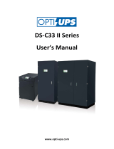
Procedure
1
RemoveFrontPanel
2
RemoveBatteryCompartmentCover
3
DisconnectOldBatteries
andRemoveOldBatteries
4
InsertNewBatteriesandConnectNewBatteries(Attachbattery
connectorsblack-to-blackandred-to-red.)
5
ReplaceBatteryCompartmentCover
6
ReplaceFrontPanel
7
RecycleOldBatteries
7
201102139 93-2882.indb 15 3/30/2011 10:04:29 AM

16
6. Storage and Service
FirstturntheUPSsystemOFF:pressthe“OFF”switchtoturnpoweroffattheUPS
system’soutlets,thendisconnecttheUPSsystem’spowercordfromthewalloutlet.Next,
disconnectallequipmenttoavoidbatterydrain.IftheUPSsystemwillbestoredforan
extendedperiodoftime,rechargetheUPSsystem’sbatteriesfullyeverythreemonthsby
pluggingtheUPSsystemintoaliveACoutletandallowingtheUPSsystemtochargefor
4-6hours.IftheUPSsystem’sbatteriesareleftdischargedforanextendedperiodoftime,
theymaysufferapermanentlossofcapacity.
AvarietyofExtendedWarrantyandOn-SiteServiceProgramsarealsoavailablefrom
TrippLite.Formoreinformationonservice,visitwww.tripplite.com/support.Before
returningyourproductforservice,followthesesteps:
1.Reviewtheinstallationandoperationproceduresinthismanualtoinsurethattheservice
problemdoesnotoriginatefromamisreadingoftheinstructions.
2.Iftheproblemcontinues,donotcontactorreturntheproducttothedealer.Instead,visit
www.tripplite.com/support.
3.Iftheproblemrequiresservice,visitwww.tripplite.com/supportandclicktheProduct
Returnslink.FromhereyoucanrequestaReturnedMaterialAuthorization(RMA)
number,whichisrequiredforservice.Thissimpleon-lineformwillaskforyourunit’s
modelandserialnumbers,alongwithothergeneralpurchaserinformation.TheRMA
number,alongwithshippinginstructionswillbeemailedtoyou.Anydamages(direct,
indirect,specialorconsequential)totheproductincurredduringshipmenttoTrippLiteor
anauthorizedTrippLiteservicecenterisnotcoveredunderwarranty.Productsshippedto
TrippLiteoranauthorizedTrippLiteservicecentermusthavetransportationcharges
prepaid.MarktheRMAnumberontheoutsideofthepackage.Iftheproductiswithinits
warrantyperiod,encloseacopyofyoursalesreceipt.Returntheproductforserviceusing
aninsuredcarriertotheaddressgiventoyouwhenyourequesttheRMA.
6.1 Storage
6.2 Service
201102139 93-2882.indb 16 3/30/2011 10:04:29 AM

17
201102139 • 932882-EN
7. Warranty Registration
WARRANTY REGISTRATION
Visit www.tripplite.com/warranty today to register the warranty for your new Tripp Lite product. You’ll be
automatically entered into a drawing for a chance to win a FREE Tripp Lite product!*
* No purchase necessary. Void where prohibited. Some restrictions apply. See website for details.
Regulatory Compliance Identification Numbers: For the purpose of regulatory compliance certifications and
identification, this Tripp Lite product has been assigned a unique series number. The series number can be
found on the product nameplate label, along with all required approval markings and information. When
requesting compliance information for this product, always refer to the series number. The series number
should not be confused with the marking name or model number of the product.
FCC Notice, Class A
This device complies with part 15 of the FCC Rules. Operation is subject to the following two conditions: (1)
This device may not cause harmful interference, and (2) this device must accept any interference received,
including interference that may cause undesired operation.
Note: This equipment has been tested and found to comply with the limits for a Class A digital device,
pursuant to part 15 of the FCC Rules. These limits are designed to provide reasonable protection against
harmful interference when the equipment is operated in a commercial environment. This equipment
generates, uses, and can radiate radio frequency energy and, if not installed and used in accordance with
the instruction manual, may cause harmful interference to radio communications. Operation of this equipment
in a residential area is likely to cause harmful interference in which case the user will be required to correct
the interference at his own expense. The user must use shielded cables and connectors with this equipment.
Any changes or modifications to this equipment not expressly approved by Tripp Lite could void the user’s
authority to operate this equipment.
WEEE Compliance Information for Tripp Lite Customers and Recyclers (European Union)
Under the Waste Electrical and Electronic Equipment (WEEE) Directive and implementing regulations, when
customers buy new electrical and electronic equipment from Tripp Lite they are entitled to:
• Send old equipment for recycling on a one-for-one, like-for-like basis (this varies depending on the country)
• Send the new equipment back for recycling when this ultimately becomes waste
The policy of Tripp Lite is one of continuous improvement. Specifications are subject to change without
notice.
1111 W. 35th Street, Chicago, IL 60609 USA
www.tripplite.com/support
201102139 93-2882.indb 17 3/30/2011 10:04:29 AM

18
Manual del Propietario
1111 W. 35th Street, Chicago, IL 60609 USA
www.tripplite.com/support
Sistemas UPS SmartOnline
™
en Rack/Torre 100% en Línea
Copyright © 2011 Tripp Lite. Todos los derechos reservados. SmartOnline es una marca comercial de Tripp Lite.
Noconvenienteparalosusosmóviles.
1. Instrucciones de Seguridad Importantes 19
2. Instalación 20
2.1 Instalación (Rack) 20
2.2 Instalación (Torre) 21
2.3 Conexión y Arranque 21
2.4 Conexiones Opcionales 22
3. Operación 25
3.1 Interruptores del Panel Frontal 25
3.2 Ajustes Operacionales Avanzados 25
3.3 Luces Indicadoras del Panel Frontal 26
3.4 Panel Posterior 28
3.5 Comunicaciones 29
4. Solución de Problemas 30
5. Reemplazo de Baterías 31
6. Almacenamiento y Reparaciones 33
6.1 Almacenamiento 33
6.2 Reparaciones 33
7. Garantía 34
English 1
Français 35
Pyññêèé 52
201102139 93-2882.indb 18 3/30/2011 10:04:29 AM
/