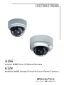
Channel Vision 6106 User manual
- Category
- Security cameras
- Type
- User manual
This manual is also suitable for

6128
6106
Outdoor WDR Vandal-Proof IR Color Dome Camera
Indoor WDR Color IR Dome Camera
1
1

1
Contents
1. SAFETY PRECAUTIONS..................................................................................2
2. INTRODUCTION...............................................................................................3
3. FEATURES ......................................................................................................... 4
4. PACKING LIST.................................................................................................. 5
5. NAME and FUNCTION of EACH PART..........................................................6
5.1 OSD Button (Menu):...............................................................................6
6. INSTALLATION.................................................................................................7
6.1 Camera Installation & Operation.............................................................7
6.2 Connect to Monitor................................................................................ 10
6.3 Connect the Power.................................................................................11
6.4 Connection Layout ................................................................................ 12
6.4.1 Connecting the Keyboard................................................................... 13
PELCO Keyboard (or compatible) Installation...........................................13
6.4.2 Connecting the Alarm......................................................................... 14
7. OPERATION.....................................................................................................15
7.1 PELCO Keyboard (or compatible) Operation.......................................15
8. SYSTEM SETUP..............................................................................................16
8.1 Digital Zoom Operation:....................................................................... 16
8.2 OSD (On Screen Display)..................................................................... 16
8.3 Sub Menu Description...........................................................................17
8.3.1 LENS TYPE....................................................................................... 17
8.3.2 EXPOSURE Setup .............................................................................17
8.3.4 WHITE BALANCE Setup.................................................................19
8.3.5 PRIVACY MASK Setup.................................................................... 20
8.3.6 EFFECT Setup: ..................................................................................21
8.3.7 NOISE REDUCTION Setup..............................................................23
8.3.8 MOTION DETECT Setup..................................................................23
8.3.9 COMMUNICATION Setup...............................................................24
8.3.10 DEFAULT Setup..............................................................................25
8.3.11 EXIT Setup.......................................................................................25
9. SPECIFICATION.............................................................................................. 26

2
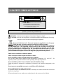
1. SAFETY PRECAUTIONS
CAUTION
RISK OF ELECTRIC SHOCK.
DO NOT OPEN!
CAUTION : CAUTION :
TO REDUCE THE RISK OF ELECTRICAL SHOCK,
DO NOT OPEN COVERS (OR BACK).
NO USER SERVICEABLE PARTS INSIDE.
REFER SERVICING TO QUALIFIED
SERVICE PERSONNEL.
WARNING: Alert the user to the presence of un-insulated ? dangerous voltage? .
CAUTION: Alert the user the presence of important operating and maintenance (Servicing)
instructions in the literature accompanying the appliance.
Disposal of Old Electrical & Electronic Equipment (Applicable in the European
Union and other European countries with separate collection systems).
This symbol indicates that this product shall not be treated as household waste. Instead it
shall be handed over to the applicable collection point for the recycling of electrical and
electronic equipment. By ensuring this product is disposed of correctly, you will help
prevent potential negative consequences for the environment and human health. For more
detailed information about recycling of this product, please contact your local city office,
your household waste disposal service or the shop where you purchased the product.
Please be extra careful not to shake the product.
Please avoid places where frequent vibrations or shocks.
Do not install the product in extreme temperature conditions.
Only use the camera under conditions where temperatures are between -10? and +50? . Be
especially careful to provide ventilation when operating under high temperatures.
Do not install the product in an environment where the humidity is high.
Unless the product is waterproof or weatherproof, otherwise it can cause the image quality to be
poor.
Do not expose to strong light (sun rays), as color filters will be discolored.
Do not spill liquid of any kind on the product.
If it gets wet, wipe it dry immediately. Alcohol or beverage can contain minerals that corrode the
electronic components.
When any abnormal occurs, make sure to unplug the unit, and contact your local dealer.
It is advised to read the Safety Precaution Guide through carefully before operating the
product, to prevent any possible danger.

3
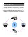
2. INTRODUCTION
650TVL
WDR
DNR
This WDR digital image camera uses a high resolution color Sony 1/3” interline transfer
Charge Coupled Device (CCD) image sensor, producing clear images reaching 650 lines of
horizontal resolution.
Using Super Wide Dynamic Range technology, this camera is able to capture both high-
luminance and low luminance subjects under a wide variety of shooting conditions. 3-D
Noise Reduction technology automatically reduces noise in low light environments after
noise reduction. The camera provides motion detection warnings, offering comprehensive
monitoring for added safety protection.

4
3. FEATURES
Excellent Sensitivity
Wide Dynamic Range (WDR)
Day & Night
Privacy Mask
High-quality WDR functionality,
perfectly shows the image details
between dark and light. The newly added
environment dynamic detection switch
enhances WDR image efficiency.
2D/ 3D DNR, captures clear images in
low light environments, saving DVR
hard disk storage space when using
MPEG/MPEG4/H.264 compression.
High sensitivity, low smear, high anti-
blooming and high S/N ratio.
High Resolution
CCD Sensor provides high resolutions
reaching 650 TV lines with crisp, clear
picture quality.
IR cut-filter with AE automatically
changes from color to B&W mode for
day and night 24-hour surveillance.
Selectable between manual Day &
Night control or from external input
signal Day & Night control.
When in low light, reduces the image
frame refresh rate and increases the
sensitivity of the camera.
Provides a motion detection alert for
more comprehensive monitoring and
specific editing of the motion detection
area. When there are changes within
the detection area, the camera
immediately issues a warning.
Built-in DC-type Vari-Focal lens with
ICR.
Control the camera easily with the
5050 RS-485 interface; Connect the
extra alarm out to combine with the
motion detection function.
Privacy image masking with free
position, supports up to 15 areas of
privacy masking zones. Privacy area
enlarges with the digital zoom-in
function.
Performance: 16x digital zoom, freeze
image, positive/ negative image, mirror
function (left/ right), reverse turn (up/
down), and 180° rotation.
All functions can be operated from OSD: AES (Automatic Electronic Shutter), AI (Auto Iris),
GC (Gain Control), WB (White Balance), BLC (Back Light compensation), and provides the
flickerless mode, and line-lock function.
OSD (On Screen Display) Setup Menu.
Camera tile setup of up to 16
alphanumeric characters
Motion Detection
Lens (C/CS Mount)
Extra Connection
OSD
Image Control
Application
Digital Slow Shutter (DSS)
Digital Noise Reduction (DNR)

5
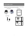
4. PACKING LIST
Check and make sure all the items shown below are included in your product package.
If something is missing, contact your dealer as soon as possible.
Dome (IR Type) User Manual
Power Adaptor
Accessories
6106
or
Outdoor IR
Dome
Indoor IR
Dome
6128

6
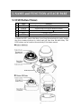
5. NAME and FUNCTION of EACH PART
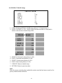
5.1 OSD Button (Menu):
No. Name Function
1
UP Digital Zoom-Out or Up direction button
2
DOWN Digital Zoom-In or Down direction button
3
RIGHT
Increase Value (++ )
4
LEFT
Decrease Value (-- )
5
ENTER Enter or Exit setup MENU
To adjust the OSD, remove the dome cover from the main body by gently turning
the cover counter-clockwise to unlock and pull free from the main body. The
OSD buttons can be found on the main body of the dome camera.

7
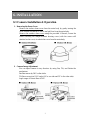
6. INSTALLATION
6.1 Camera Installation & Operation
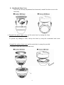
1. Removing the Dome Cover
Remove the indoor dome cover from the main body by gently turning the
cover counter-clockwise to unlock and pull free from the main body.
Remove the outdoor dome cover using the provided L-Wrench, loosen the
screws securing the temper-resistant housing cover (with the screws still
attached on the cover) to unlock the cover from the main body.
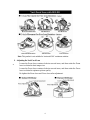
2. Camera Image Adjustment
You can adjust camera to any directio
n by using Pan, Tilt, and Rotate the
mechanism.
Pan Base moves by 360° on the whole.
Tilt Base covers total 119° angle (64° to one side and 55° to the other side).
Angle range of Rotate Base is 360°.

8
Note: This product is not suitable for horizontal 360° continuous rotation.
3. Adjusting the Vari-Focal Lens
z
lever to obtain the best image view.
Loosen the Focus lever counter-clockwise several turns, and then rotate the Focus
lever to obtain the optimum picture quality.
Re-tighten the Zoom lever and Focus lever after adjustment.
Loosen the Zoom lever counter-clockwise several turns, and then rotate the Zoom

9
4. Attaching the Dome Cover
After all the necessary adjustments have been made, reinstall the dome cover to the
main body.
z
Reinstall the indoor dome cover and the main body by turning the dome
clockwise until it locks into place
To prevent any damage or theft, lock-up the dome by using the countersunk head screw.
Reinstall the outdoor dome cover and the main body by using the provided
L-Wrench to fasten the cover to the main body.

10
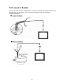
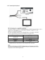
6.2 Connect to Monitor
Connect the Video-out port of the camera to a monitor. Since the connecting method varies
depending on the instrument, refer
to the manual supplied with the instrument
for more information.

11
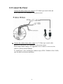
6.3 Connect the Power
Connect the indoor dome video output to a 75 Ohms type coaxial cable and
the DC-Jack or AC/ DC-Terminator to the power source.
zz
Connect the outdoor dome video output to a 75 Ohms type coaxial cable
and the DC-Jack or AC/ DC-Terminator to the power source.
When using conduit cabling, it is suggest
ed to use a metal to cover over the
cables to prevent external damage.
To weatherproof, place weatherproof adhesive tape (P.T.F.E. THREAD SEAL TAPE)
onto the metal cover before installation.

12
Note: Power adapter is sold separately.
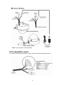
6.4 Connection Layout
To connect the keyboard and alarm, please follow the setup guide shown below:

13
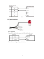
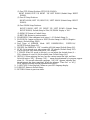
6.4.1 Connecting the Keyboard
PELCO Keyboard (or compatible) Installation
The RS-422 interface is used for communicati
ng with a PELCO keyboard. Refer to Fig. 1;
connect R+ of the camera to T+ of the PELCO keyboard. Connect R- of the
camera to T- of the PELCO keyboard.
The user can adjust Camera ID via rear
panel keys or via remote commands.
Protocol, Speed and Parity should only be adjusted via rear panel keys.
Communication Setting
0 ~ 253 for P protocol
CAMERA ID
1 ~ 255 for D protocol
PROTOCOL PELCO
SPEED 2400, 4800, 9600, 19200
PARITY NONE
The speed of camera should be the same as the speed of the keyboard.
Adjusted function is only effective, after exiting the OSD setup menu.
Note:
Maximum cable distance for RS-485 coMmunication over 24-gauge wire is 4,000
feet (1,219 m). Recommend using a shielded twisted pair cable that meets the basic
requirements for EIA RS-485 applications.

14
Fig.1
6.4.2 Connecting the Alarm
Alarm Installation
Connect GND and AL of the camera to the GND and AL of the alarm.
Note: The alarm is triggered by motion detection.

15
7. OPERATION
1. Mount the camera on the mounting bracket by using the hole on the top or bottom
of the camera, and by using the enclosed mounting block, secured by 2 screws.
2. Connect the video output to the monitor or other video device via a 75 Ohms type
coaxial cable.
3. Power Input Terminal (Dual Power): the camera accepts both AC 24V and DC 12 V
power sources (non-polarity).
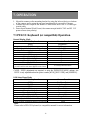
7.1 PELCO Keyboard (or compatible) Operation
Normal Display Mode
PELCO Keyboard Camera Function
OPEN Brightness +
CLOSE Brightness -
Twist Joystick clockwise or Zoom In Zoom Tele
Twist Joystick counterclockwise or Zoom Out Zoom Wide
NEAR None
FAR None
Move Joystick Left None
Move Joystick Right None
Move Joystick Up None
Move Joystick Down None
Enter 95; Hold the PRESET key (approximately five
seconds) until the main menu appears on the screen.
Accessing OSD Main Menu
Note
:
CLOSE / OPEN adjustments are required to meet the EXPOSURE MODE settings, size
LEVEL is only adjustable when the option is under
[WDR], [BLC US
ER], and [NORMAL].
OSD Setup Menu Mode
PELCO Keyboard Camera Function
OPEN Sub Menu Enter
CLOSE Sub Menu Exit
NEAR Cursor Up
FAR Cursor Down
Move Joystick Left Decrease (-)
Move Joystick Right Increase (+)
Move Joystick Up Cursor Up
Move Joystick Down Cursor Down
Twist Joystick clockwise or Zoom In None
Twist Joystick counterclockwise or Zoom Out None
Note:
Please refer to PELCO Keyboard (or compatible) manual for more information.

16
8. SYSTEM SETUP
8.1 Digital Zoom Operation:
Under normal display (before entering the OSD menu), use S(T)/ T(W) button to
control the digital zoom (zoom range: 1 x ~ 16 x).
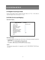
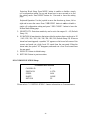
8.2 OSD (On Screen Display)
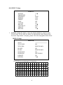
Main Menu Display
MAIN MENU V.9729
LENS TYPE
EXPOSURE
WHITE BALANCE
PRIVACY MASK
EFFECT
NOISE REDUCTION
MOTION DETECT
COMMUNICATION
DEFAULT
EXIT
MANUAL/DC
? ?
? ?
? ?
? ?
? ?
? ?
? ?
ON
Main Menu Setupß
⇓
In order to display the setup menu on the screen, set the menu command or press the
button panel.
Use 匀(T)/ 吀(W) control buttons to select each item.
Use ? (-- )/ ? (++ ) control buttons to change the data.
Use MENU control button to ENTER/ EXIT the menu display.
<Note>
For maximum image quality it is suggested to use DC LENS PENTAX TS812E 8mm
1:1.2 CS.

17
8.3 Sub Menu Description
8.3.1 LENS TYPE
Built-in DC-type Vari-Focal lens with ICR (although the camera OSD supports
both DC-type and Manual-type lenses, it is fixed to DC type because the camera
is built-in only with a DC-type Vari-Focal lens).
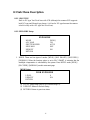
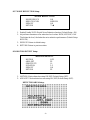
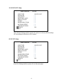
8.3.2 EXPOSURE Setup
EXPOSURE
MODE
AGC MAX
SHUTTER SPEED
DESS MAX
DEFAULT
RETURN
[WDR]
128
AUTO
OFF
ON
1. MODE: There are four types of modes: [WDR] / [BLC SMART] / [BLCUSER] /
[NORMAL]. When the function option is set to BLC SMART, it indicates that the
backlight compensation is calculated by the system. Press MENU under [WDR] /
[BLCUSER] / [NORMAL] mode to enter next page.
[WDR] Setup:
WDR EXPOSURE
LEVEL
DEFAULT
RETURN
8
ON
(1) LEVEL: Setup range from 0-40 (Default Setup: 8).
(2) DEFAULT: Return to Default Setup.
(3) RETURN: Return to previous status.

18
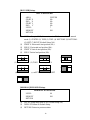
[BLCUSER] Setup:
BLC EXPOSURE
AREA
START X
END X
START Y
END Y
LEVEL
DEFAULT
RETURN
CENTER
NA
NA
NA
NA
7
ON
(1) AREA: Setup to BLC, the area is se
t as BLC area and under manual
mode (1) CENTER (2) TOPS (3) TOPL (4) BOTTOMS (5) BOTTOML
(6) LEFT (7) RIGHT (Default Setup: NA).
(2) START X: Horizontal start position (NA).
(3) END X: Horizontal end position (NA).
(4) START Y: Vertical start position (NA).
(5) END Y: Vertical end position (NA).
(1) C ENTER (2) T OPS (3) T OP L
(4) BOTTOMS (5) BOTTOML (6) LEFT
(1) RIGHT
[NORMAL] EXPOSURE Setup:
NORMAL EXPOSURE
LEVEL
DEFAULT
RETURN
96
ON
(1) LEVEL: Setup range from 0-255 (Default Setup: 96).
(2) DEFAULT: Return to Default Setup.
(3) RETURN: Return to previous status.

19
2. AGC MAX: Set AGC MODE to AUTO, AGC MAX setup range = 0~255.
3. SHUTTER SPEED consists of 9 types of modes: AUTO, NORMAL, FLICKERLESS
(NTSC: 1/60 and PAL: 1/50), 1/250, 1/1000, 1/2000, 1/4000, 1/10000, 1/20000,
1/50000 and 1/100000 (Default Setup: NORMAL).
4. DSS MAX: Low speed shutter control, offers optimal brightness level. Therefore, in
dark scene, raise the value higher than the the brig
htness level (Field
Range: 2~256, Default
Setup: OFF).
5. DEFAULT: Return to default setup.
6. RETURN: Return to previous status.
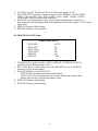
8.3.4 WHITE BALANCE Setup:
WHITE BALANCE
WB MODE
RED GAIN
BLUE GAIN
PUSH AUTO
DEFAULT
RETURN
AUTO
NA
NA
NA
ON
st
1. WB MODE: Five types of mode - AUTO, INDOOR, OUTDOOR, MANUAL,
and PUSH AUTO (Default Setup: AUTO).
2. RED GAIN/ BLUE GAIN operate only when WB MODE is set to MANUAL,
otherwise it is NA (Not Available).
3. When WB MODE is set to PUSH AUTO:
PUSH AUTO ON: Enable auto tracing white balance.
PUSH AUTO OFF: Depending on environment, disable auto tracing white
balance and record the current white balance value.
4. DEFAULT: Return to default setup.
5. RETURN: Return to previous status.
Page is loading ...
Page is loading ...
Page is loading ...
Page is loading ...
Page is loading ...
Page is loading ...
Page is loading ...
Page is loading ...
-
 1
1
-
 2
2
-
 3
3
-
 4
4
-
 5
5
-
 6
6
-
 7
7
-
 8
8
-
 9
9
-
 10
10
-
 11
11
-
 12
12
-
 13
13
-
 14
14
-
 15
15
-
 16
16
-
 17
17
-
 18
18
-
 19
19
-
 20
20
-
 21
21
-
 22
22
-
 23
23
-
 24
24
-
 25
25
-
 26
26
-
 27
27
-
 28
28


Channel Vision 6106 User manual
- Category
- Security cameras
- Type
- User manual
- This manual is also suitable for
Ask a question and I''ll find the answer in the document
Finding information in a document is now easier with AI
Related papers
-
Epcom 6901 User manual
-
-
Channel Vision 6010-B User manual
-
-
-
-
-
-
-
Other documents
-
Eneo TVD-1080V2812IR User manual
-
Eneo HDB-2180Z03IR Operating instructions
-
-
ERNITEC Orion/3-DN Outdoor Installation & User's Instructions
-
-
-
-
Wirepath WPS-765-DOM-AH-BL Owner's manual
-
Vitek VTC-CB4MZ39 User manual
-
 Digital Watchdog DWC-D3563DIR User manual
