Page is loading ...

Installation Instructions
Modernist
®
Island (Ceiling Mount)
Range Hood
DHD36M967IM, DHD36M967IS, DHD48M977IM, DHD48M977IS
Part No. 113850 Rev. A
Approved for use with all Dacor
®
ranges and cooktops.

II
Installation Instructions .................................................................. 4
Verifying Package Contents ................................................................. 4
Installing the Hood ................................................................................4
Verifying Function ..................................................................................6
Installation Checklist ............................................................................. 6
Wiring Diagram .................................................................................7
Important Safety Instructions .........................................................1
Important Information .......................................................................... 1
General Safety Precautions .................................................................. 1
Installation Specifications ...............................................................2
Performance Specifications .................................................................2
Electrical Specifications ........................................................................ 2
Product Dimensions...............................................................................2
Planning the Location ...........................................................................3
Planning the Ducting .............................................................................3
TABLE OF CONTENTS
BEFORE YOU BEGIN
CUSTOMER ASSURANCE INFORMATION
Installer
• For safety and to minimize problems, read this manual thoroughly before installing the hood.
• Leave this manual with the owner.
Owner
Keep this manual for personal and professional reference.
NOTE: Dacor
®
is not responsible for service needed to correct a faulty installation.
If you have questions or installation/repair/warranty issues, con-
tact Dacor Customer Assurance. Have available the hood model
and serial numbers, which are on the hood data label (underside
of chassis, above the filters; see the graphic at right).
Dacor Customer Assurance
Phone: 833-35-ELITE (833-353-5483) USA, Canada
a.m.p.m. Pacific Time
Website: www.dacor.com/customer-care/contact-us
All specifications are subject to change without notice. Dacor
assumes no liability for changes to specifications.
© 2018 Dacor, all rights reserved.
READ AND SAVE THESE INSTRUCTIONS

1
Important Information
• The Important Safety Instructions and warnings in this manual
cannot cover all possible issues. Use caution and common
sense when installing the hood.
• Contact Dacor Customer Assurance about issues you cannot
resolve. (See previous page for contact info.)
Safety Symbols and Labels
DANGER
Immediate hazard that WILL severely injure or kill.
WARNING
Hazard/unsafe practice that COULD severely injure or kill.
CAUTION
Hazard/unsafe practice that COULD cause minor personal injury and
property damage.
DANGER
To avoid explosion/fire, do not store/use flammable or explosive vapors
and liquids (ex: gasoline, alcohol) in/on/near the hood. Keep containers
that could explode (ex: aerosol cans) away from the cooking unit and hood.
WARNING
TO REDUCE RISK OF FIRE, ELECTRIC SHOCK, AND PERSONAL INJURY:
• Use the hood only as specified in the provided literature. If you have
questions, contact Dacor Customer Assurance.
• Before service/maintenance, turn off power at the service panel
and lock the panel. If locking is not an option, securely fasten a
prominent warning sign to the panel.
• Installation-related work must be done by qualified person(s) per
applicable codes/standards, including fire-rated construction.
• Ample air is needed for proper gas combustion/exhaust up the hood flue
to prevent backdraft. Follow the cooking-unit manufacturer’s guidelines,
also standards such as those published by the Nat'l Fire Protection
Association (NFPA); the American Society for Heating, Refrigeration, and
Air Conditioning Engineers (ASHRAE); and local authorities.
• Know the location of utilities before breaching a wall or ceiling.
• Always vent exhaust to the outdoors.
CAUTION
The hood is for general cooking ventilation only. Do not vent
hazardous/explosive vapors through the hood.
IMPORTANT SAFETY INSTRUCTIONS
General Safety Precautions
To reduce risk of fire, electric shock, and serious injury/death dur-
ing installation, follow basic safety precautions, including:
WARNING
• Follow the information in this manual exactly to avoid fire/explosion
which may cause property damage and personal injury or death.
• If the hood is damaged when received, contact the dealer immedi-
ately; do not install a damaged unit.
• Install the hood per the instructions in this manual and the require-
ments specified by the cooking-unit manufacturer. Improper
installation, adjustment, modification of the unit can cause serious
personal injury or property damage, and voids the warranty. Dacor is
not financially responsible for property damage, personal injury, and
repairs caused by faulty installation.
• The owner shall install/repair/replace hood parts only as specifically
instructed in the product literature. A qualified technician shall per-
form all other service.
• Keep all packaging material away from children.
• Do not use an extension cord or adapter plug.
• The installer shall show the owner the power source so the owner
can turn power to the hood on/off as needed.
• Read the User Manual completely before operating the hood.
• Do not tamper with the hood controls.
• If the hood and cooking unit are near a window, avoid window dress-
ings that could blow over the appliances.
• Do not let children/pets near the hood during installation or leave
items of interest to children on/around the appliances.
• Minimum distance between cooking surface and hood bottom is 26”
see the cooking unit Installation Instructions for specific dimensions.
• Use only metal ducting.

2
Product Dimensions
IMPORTANT: The installed hood-bottom-to-cook-surface distance
depending on the cooking unit. (See the cooking unit's
Installation Instructions for details.)
DHD36
DHD48
Performance Specifications
All Models
Blower
Blower Speeds 4
Lights
Filters Stainless-steel baffle type (dishwasher safe)
Exhaust 5" (DHD36), 8" (DHD48)
Total Connected Load
Circuit Requirement
Individual Models
Model Fans Lights Filters Max. Current Draw
DHD36S 1 4 2 4.2 Amp
DHD48S 2 6 3
Electrical Specifications
WARNING
Electrical service to the hood must be installed by a licensed electrician.
The owner shall ensure the hood's electrical connection is made
by a licensed electrician. The process, including minimum supply
wire size and grounding, must follow local codes and the National
be obtained from:
National Fire Protection Association
1 Batterymarch Park
dedicated, grounded, 3-wire (hot, neutral, ground) circuit protect-
ed by a 15-A circuit breaker or time-delay fuse. Install the junction
attached to a ceiling joist).
INSTALLATION SPECIFICATIONS
unless otherwise stated

3
• Local building codes may require makeup air systems with ven-
tilation systems that move air at greater than the specified rate
(CFM), which depends on the locale. Consult an HVAC specialist
concerning local requirements and to ensure best performance.
• The owner buys all ducting material (incl. screws and duct tape).
• Always plan for the most direct route to the outside.
• The hood exhaust connects to an 8" round duct. You can increase
duct size over the course of the run, but to prevent backdraft,
never decrease the size. If existing duct work is smaller than 8" in
diameter, remove it and replace it with 8" ducting.
• Fasten all ducting joints with sheet-metal screws, and tape all
joints with certified silver or duct tape. Support the ducting with
sheet-metal screws as needed.
• To prevent backdraft, a damper at the duct outlet may be needed.
• Ensure ducting does not interfere with ceiling/wall supports.
Calculating the Maximum Duct-Run Length
the actual maximum run, subtract the equivalent length of each
EQUIVALENT LENGTHS
Piece Subtract Piece Subtract
5 ft.
3 ft. 2 ft.
round transition
25 ft.
round transition
4 ft.
Roof cap Wall cap w/damper
For equivalent length, contact the manufacturer or a qualified HVAC specialist.
Ducting Design Tips
• For transitions/turns, use as few sharp angles as possible. (Two
• Keep turns as far from the hood exhaust as possible, and keep
as much space between bends as possible.
• For best performance, use round ducting, especially for elbows.
• Try to keep at least 24" of straight duct between elbows.
• Avoid using “S” or “back-to-back” elbows.
• In very cold regions, use thermal breaks (ex: a short section of
non-metallic duct) to avoid indoor heat loss. Put the break as
close as possible to the outside pass-through point.
• Do not use flexible metal ducting.
• Do not use ducting that is smaller in cross-sectional area than
the types recommended above.
Planning the Location
WARNING
• Observe all governing regulations during planning/installation.
Contact the local building department for details.
• To avoid injury and property damage from the hood falling, use
only the provided mounting bracket.
• Situate the hood for convenient access, and verify that power
can be supplied to the site.
• The selected model must be at least as wide as the cooktop.
• Install the hood and cooking unit so they can be removed for
service.
• Minimum dimensions must not be exceeded (see Pg. 2). All
dimensions are minimums unless otherwise noted.
• The ceiling plate must be attached directly to ceiling joists or to
a reinforced mounting block secured to the joists.
• The mounting bracket must be level and centered directly
above the cooking surface.
• Air intake through the hood could create negative air pressure,
from the heat source; thus, the kitchen should be well-ventilated
when the hood and cooking unit are on.
Planning the Ducting
WARNING
• To keep combustion byproducts, smoke, and odors out of the home
and to improve efficiency, tape all duct joints securely.
• Use only ducting accepted by state, municipal, and local codes.
• Do not install an additional in-line or external blower to increase the
length of the duct run. Even small differences in air-flow rates can
greatly reduce the hood's ability to draw air.
CAUTION
• To reduce fire risk and to properly exhaust air, always vent exhaust
to the outdoors.
• Do not merge/combine the island-hood ducting with that of any
other vented appliance. The hood must have its own ducting.
INSTALLATION SPECIFICATIONS

4
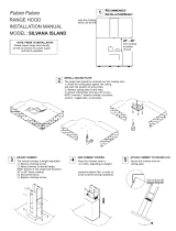
Attaching the Ceiling Plate
1. Holding the ceiling plate in place against the ceiling:
a. Trace the center ducting hole (incl. cabling notch) for cut-
ting the hole through which the cabling/ducting will pass.
b. Mark where the holes will be drilled for anchoring the ceil-
ing plate to the ceiling.
2. Cut the ducting hole, then drill four 8-mm holes at the respec-
tive marks, and insert an anchor in each hole.
3. Align the ceiling plate with the ducting hole and anchors, and
insert and tighten 4 screws, securing the plate to the ceiling.
Making the Electrical Connections
WARNING
• Before making the electrical connection, ensure the home power
supply to the hood is turned off at the source, and that the electrical
connections will conform to the requirements on Pg. 3.)
• Do not ground the hood to the neutral (white) power-supply wire but
to a separate, proper ground wire installed by a licensed electrician.
1. Run the home-supply cable through the hole in the ceiling
down to the hood superstructure.
2. Remove the junction-box cover and the knockout on the right
side of the junction box, and feed the home power-supply cable
through the hole.
3. Connect the neutral (white) power-supply wire to the terminal
opposite the hood white wire.
4. Connect the hot (black) power-supply wire to the terminal
opposite the hood black wire.
5. Connect the ground (green) power-supply wire to the terminal
opposite the hood green wire.
6. Re-install the hood junction-box cover with the two screws.
Verifying Package Contents
Uncrate the hood, and verify that all parts are present.
F Chassis
F
F Chimney framework (2 pcs)
F Chimney covers (2 pcs—upper, with grates; lower)
F Ceiling plate
F Mounting hardware (hex nuts, washers: 4 ea.; plastic anchors:
4; 1 ½" Phillips-head screws: 4; safety screws: 4)
F Stainless-steel cleaner (1 two-oz. bottle)
F Product literature (Installation Instructions, User Manual).
If anything is missing/damaged, contact the dealer immediately.
Do not install a damaged/incomplete unit.
Installing the Hood
WARNING
• Observe all local codes/ordinances. Contact the local building
department for details.
• The owner shall ensure a qualified technician installs the hood as
directed in this manual.
• Do not install the hood unless the power supply meets the electrical
specifications on Pg. 2.
• At the installation site, verify that no utilities/joists/ducting/trusses
are present before cutting/drilling into the ceiling.
• At least two people are needed for safe installation.
Removing the Filters
Before starting the installation, remove the filters.
1. Grasp the filter handle, and push rearward.
2. When the front of the filter clears the front slot, tilt it down,
then pull it out of the rear slot and away from the hood.
INSTALLATION INSTRUCTIONS
Filter Handle
Plastic
Anchor (4)
8 mm Screw
(4)
Ceiling Plate
Cabling
Notch
(faces front)
Black
Green
Home
Supply Line
Hood Green
(ground) Wire
Hood Junction
Box
White

5
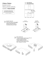
Attaching the Hood to the Ceiling
1. Lift the hood chassis (do not lift by the chimney structure) so
the 4 spring clips in the ceiling plate engage the slots in the
upper chimney piece.
2. Secure the hood/chimney assembly to the ceiling plate with
the 4 safety screws (previous graphic).
3. Connect the hood duct to the exhaust hole with duct tape only.
4. Lift the upper chimney cover (previous graphic), and secure it
to the ceiling plate with the 2 self-tapping screws. (See Step 8.)
5. Install the filters.
6. Turn on power to the hood at the power source.
Attaching the Chimney Structure
1. Align the 4 screw holes on the base chimney piece with the
threaded studs on the chassis superstructure.
2. Place a washer and nut on each stud, and tighten the nuts.
3. (Keeping the cabling within the notch in the ceiling plate)
Place a length of ducting over the collar on the fan outlet, and
secure the ducting with a hose clamp.
4. Slip the upper chimney piece over the base piece, adjust the
height (keeping in mind the cooktop-to-hood minimum dis-
tance), and secure the chimney pieces together.
5. Slip the 2 chimney covers over the chimney framework, rest-
ing the covers on the hood chassis. (The covers remain loose
for the time being.)
INSTALLATION INSTRUCTIONS
Washer and
Nut (4 ea.)
Hood
Chassis
Base Chimney
Piece
Threaded
Stud (4)
Upper
Chimney Cover
Lower
Chimney Cover
Ceiling Plate
Hood/
Chimney
Assembly
Upper
Chimney Cover
Attach Upper
Chimney
Cover here
(both sides)
Spring Clip (4)
Safety
Screw (4)

6
Verifying Function
1. Switch on power at the circuit-breaker panel or fuse box.
2. If the control panel is not lit, remove the filters, and turn on
the main power switch (behind the filters inside the hood;
install the filters.
3. Tap the light key; verify that all lights come on.
4. Tap the light key to turn the lights off.
5. Tap blower-speed increase ( + ); verify that one light appears
on the indicator and that the blower is on low speed.
6. Quickly tap + three times. (Verify that with each tap, the num-
ber of lights on the speed indicator increases and that blower
speed increases accordingly.)
Tap-hold blower-speed decrease ( - ) until the blower turns off.
If the hood fails to operate properly:
• verify that power is supplied to the hood.
• verify the electrical connections are correct.
•
If the hood still does not work, contact Dacor Customer
Assurance: 833-35-ELITE (833-353-5482). Do not try to repair the
hood yourself. If you need service, have available the model/serial
numbers (see inside front cover) when you call.
Dacor is not financially responsible for correcting problems due to
faulty installation.
INSTALLATION INSTRUCTIONS
Installation Checklist
WARNING
The installer should complete this checklist to ensure proper installa-
tion, the ultimate responsibility lies with the owner.
□ Is the ceiling plate installed as instructed on Pg. 4?
□ Is the hood secured to the ceiling plate as instructed on Pg. 5?
□ Is the ducting properly installed? Are joints attached with
sheet-metal screws and wrapped with duct tape? (See Pg. 3)
□ Is the hood wired and grounded as instructed and according to
applicable codes? (See Pgs. 2, 4. )
□ Are the filters installed as instructed in the User Manual?
□ Was proper function verified?
□ Was power to the hood turned on at the power source?
□ Was the warranty activated online or the warranty card filled
out and mailed?

7
WIRING DIAGRAM

8
NOTES

9
NOTES

Dacor ∙ 14425 Clark Avenue, City of Industry, CA 91745 ∙ Phone: (800) 793-0093 ∙ Fax: (626) 403-3130 ∙ www.dacor.com
/