Gigabyte GA-EG45M-UD2H User manual
- Category
- Motherboards
- Type
- User manual
This manual is also suitable for

GA-EG45M-UD2H
LGA775 socket motherboard for Intel
®
Core
TM
processor family/
Intel
®
Pentium
®
processor family/Intel
®
Celeron
®
processor family
User's Manual
Rev.1002
12ME-EG45MUD2H-1002R

Mar. 27, 2009
Motherboard
GA-EG45M-UD2H
Motherboard
GA-EG45M-UD2H
Mar. 27, 2009

Copyright
© 2009 GIGA-BYTE TECHNOLOGY CO., LTD. All rights reserved.
The trademarks mentioned in this manual are legally registered to their respective owners.
Disclaimer
Information in this manual is protected by copyright laws and is the property of GIGABYTE.
Changes to the specifications and features in this manual may be made by GIGABYTE without prior
notice. No part of this manual may be reproduced, copied, translated, transmitted, or published in any
form or by any means without GIGABYTE's prior written permission.
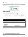
Documentation Classifications
In order to assist in the use of this product, GIGABYTE provides the following types of documentations:
For quick set-up of the product, read the Quick Installation Guide included with the product.
For detailed product information, carefully read the User's Manual.
For instructions on how to use GIGABYTE's unique features, read or download the
information on/from the Support\Motherboard\Technology Guide page on our website.
For product-related information, check on our website at:
http://www.gigabyte.com.tw
Identifying Your Motherboard Revision
The revision number on your motherboard looks like this: "REV: X.X." For example, "REV: 1.0"
means the revision of the motherboard is 1.0. Check your motherboard revision before updating
motherboard BIOS, drivers, or when looking for technical information.
Example:

- 4 -
Table of Contents
Box Contents ................................................................................................................. 6
Optional Items ................................................................................................................. 6
GA-EG45M-UD2H Motherboard Layout ........................................................................ 7
Block Diagram................................................................................................................ 8
Chapter 1 Hardware Installation .................................................................................... 9
1-1 Installation Precautions ..................................................................................... 9
1-2 Product Specifications .................................................................................... 10
1-3 Installing the CPU and CPU Cooler.............................................................. 13
1-3-1 Installing the CPU ................................................................................................ 13
1-3-2 Installing the CPU Cooler ................................................................................... 15
1-4 Installing the Memory ..................................................................................... 16
1-4-1 Dual Channel Memory Configuration................................................................ 16
1-4-2 Installing a Memory............................................................................................. 17
1-5 Installing an Expansion Card ......................................................................... 18
1-6 Back Panel Connectors ................................................................................. 19
1-7 Internal Connectors ........................................................................................ 22
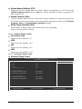
Chapter 2 BIOS Setup................................................................................................. 35
2-1 Startup Screen ................................................................................................ 36
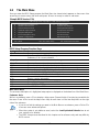
2-2 The Main Menu .............................................................................................. 37
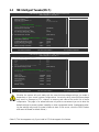
2-3 MB Intelligent Tweaker(M.I.T.) ....................................................................... 39
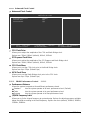
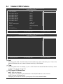
2-4 Standard CMOS Features ............................................................................. 46
2-5 Advanced BIOS Features.............................................................................. 48
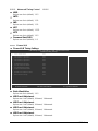
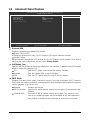
2-6 Advanced Chipset Features ........................................................................... 51
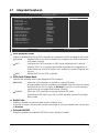
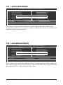
2-7 Integrated Peripherals ..................................................................................... 53
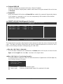
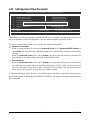
2-8 Power Management Setup ............................................................................. 56
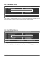
2-9 PnP/PCI Configurations................................................................................. 58
2-10 PC Health Status ........................................................................................... 59
2-11 Load Fail-Safe Defaults ................................................................................... 60
2-12 Load Optimized Defaults................................................................................. 60
2-13 Set Supervisor/User Password..................................................................... 61
2-14 Save & Exit Setup......................................................................................... 62
2-15 Exit Without Saving ....................................................................................... 62

- 5 -
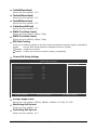
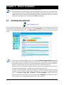
Chapter 3 Drivers Installation ...................................................................................... 63
3-1 Installing Chipset Drivers ............................................................................... 63
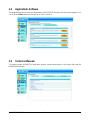
3-2 Applications Software ..................................................................................... 64
3-3 Technical Manuals.......................................................................................... 64
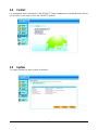
3-4 Contact........................................................................................................... 65
3-5 System........................................................................................................... 65
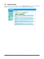
3-6 Download Center............................................................................................ 66
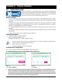
Chapter 4 Unique Features......................................................................................... 67
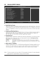
4-1 Xpress Recovery2 ......................................................................................... 67
4-2 BIOS Update Utilities..................................................................................... 70
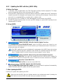
4-2-1 Updating the BIOS with the Q-Flash Utility...................................................... 70
4-2-2 Updating the BIOS with the @BIOS Utility ....................................................... 73
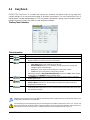
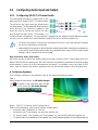
4-3 EasyTune 6.................................................................................................... 74
4-4 Dynamic Energy Saver Advanced ................................................................ 75
4-5 Q-Share ......................................................................................................... 77
4-6 Time Repair .................................................................................................... 78
Chapter 5 Appendix .................................................................................................... 79
5-1 Configuring SATA Hard Drive(s) .................................................................... 79
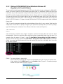
5-1-1 Configuring the Onboard SATA Controller......................................................... 79
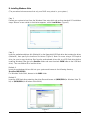
5-1-2 Making a SATA RAID/AHCI Driver Diskette for Windows XP........................ 85
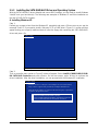
5-1-3 Installing the SATA RAID/AHCI Driver and Operating System ...................... 86
5-2 Configuring Audio Input and Output................................................................. 91
5-2-1 Configuring 2/4/5.1/7.1-Channel Audio ............................................................ 91
5-2-2 Installing the S/PDIF In Cable (Optional)........................................................... 93
5-2-3 Enabling the Dolby Home Theater Function .................................................... 95
5-2-4 Configuring Microphone Recording ................................................................... 96
5-2-5 Using the Sound Recorder................................................................................. 98
5-3 Troubleshooting ............................................................................................... 99
5-3-1 Frequently Asked Questions ............................................................................. 99
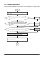
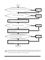
5-3-2 Troubleshooting Procedure .............................................................................. 100
5-4 Regulatory Statements ................................................................................. 102

- 6 -
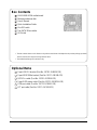
Box Contents
GA-EG45M-UD2H motherboard
Motherboard driver disk
User's Manual
Quick Installation Guide
One IDE cable
Two SATA 3Gb/s cables
I/O Shield
• The box contents above are for reference only and the actual items shall depend on the product package you obtain.
The box contents are subject to change without notice.
• The motherboard image is for reference only.
Optional Items
2-port USB 2.0 bracket (Part No. 12CR1-1UB030-5*R)
2-port IEEE 1394a bracket (Part No. 12CF1-1IE008-0*R)
S/PDIF in cable (Part No. 12CR1-1SPDIN-0*R)
2-port SATA power cable (Part No. 12CF1-2SERPW-0*R)
COM port cable (Part No. 12CF1-1CM001-3*R)
LPT port cable (Part No. 12CF1-1LP001-0*R)

- 7 -
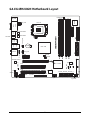
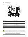
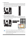
GA-EG45M-UD2H Motherboard Layout
KB_USB
LGA775
ATX
GA-EG45M-UD2H
USB
LAN
F_AUDIO
AUDIO
FDD
PCIEX16
IT8718
IDE
DDR2_1
ATX_12V
ESATA
1394
USB
HDMI
CPU_FAN
OPTICAL
LPT
DVI
VGA
Intel
®
G45
DDR2_2
DDR2_3
DDR2_4
CI
F_PANEL
PHASE LED
SATA2_0
Intel
®
ICH10R
SATA2_1
SATA2_2
PWR_LED
SATA2_3
CLR_CMOS
SATA2_4
TSB43AB23
F_USB3
F_USB2F_USB1
B_BIOS
F1_1394
PCIEX1
M_BIOS
CD_IN
PCI1
BATTERY
CODEC
PCI2
SPDIF_I
SYS_FAN
COMA
SPDIF_O
Level Shifter
Level Shifter
RTL8111C/D(L)
JMicron 368

- 8 -
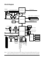
Block Diagram
CPU CLK+/-
(400(O.C.)/333/266/200 MHz)
LGA775
Processor
Intel
®
G45
LPC BUS
Intel
®
ICH10R
Line Out
MIC
CODEC
Line In
S/PDIF In
S/PDIF Out
Side Speaker Out
Center/Subwoofer Speaker Out
Surround Speaker Out
2 PCI
PCI Bus
2 IEEE 1394
TSB43AB23
LAN
LPT Port
Floppy
COM Port
IT8718
Host
Interface
DDR2 1066(O.C.)/800/667 MHz
Dual Channel Memory
1 PCI Express x1
PCI Express Bus
PCIe CLK
(100 MHz)
x1
ATA-133/100/
66/33 IDE
Channel
x1
JMicron
368
GMCH CLK
(400(O.C.)/333/266/200 MHz)
RJ45
PS/2 KB or Mouse
Dual BIOS
5 SATA 3Gb/s
12 USB Ports
1 eSATA 3Gb/s
1 PCI Express x16
(Note)
SwitchSwitch
PCIe CLK
(100 MHz)
PCI Express x16
HDMI DVI-D
D-Sub
x4 x4
x8
(Note) The PCI Express x16 slot share the PCI Express x16 bus with the HDMI and the DVI-D ports.
When the PCI Express x16 slot is in use, the HDMI and the DVI-D ports become unavailable.
RTL8111C/D(L)

Hardware Installation- 9 -
1-1 Installation Precautions
The motherboard contains numerous delicate electronic circuits and components which can become
damaged as a result of electrostatic discharge (ESD). Prior to installation, carefully read the user's
manual and follow these procedures:
• Prior to installation, do not remove or break motherboard S/N (Serial Number) sticker or
warranty sticker provided by your dealer. These stickers are required for warranty validation.
• Always remove the AC power by unplugging the power cord from the power outlet before
installing or removing the motherboard or other hardware components.
• When connecting hardware components to the internal connectors on the motherboard,
make sure they are connected tightly and securely.
• When handling the motherboard, avoid touching any metal leads or connectors.
• It is best to wear an electrostatic discharge (ESD) wrist strap when handling electronic
components such as a motherboard, CPU or memory. If you do not have an ESD wrist strap,
keep your hands dry and first touch a metal object to eliminate static electricity.
• Prior to installing the motherboard, please have it on top of an antistatic pad or within an
electrostatic shielding container.
• Before unplugging the power supply cable from the motherboard, make sure the power supply
has been turned off.
• Before turning on the power, make sure the power supply voltage has been set according to
the local voltage standard.
• Before using the product, please verify that all cables and power connectors of your hardware
components are connected.
• To prevent damage to the motherboard, do not allow screws to come in contact with the
motherboard circuit or its components.
• Make sure there are no leftover screws or metal components placed on the motherboard or
within the computer casing.
• Do not place the computer system on an uneven surface
.
• Do not place the computer system in a high-temperature environment.
• Turning on the computer power during the installation process can lead to damage to system
components as well as physical harm to the user.
• If you are uncertain about any installation steps or have a problem related to the use of the
product, please consult a certified computer technician.
Chapter 1 Hardware Installation

GA-EG45M-UD2H Motherboard - 10 -
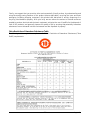
1-2 Product Specifications
CPU Support for an Intel
®
Core
TM
2 Extreme processor/
Intel
®
Core
TM
2 Quad processor/Intel
®
Core
TM
2 Duo processor/
Intel
®
Pentium
®
processo/Intel
®
Celeron
®
processor
in the LGA 775 package
(Go to GIGABYTE's website for the latest CPU support list.)
L2 cache varies with CPU
Front Side Bus 1600(O.C.)/1333/1066/800 MHz FSB
Chipset North Bridge: Intel
®
G45 Chipset
South Bridge: Intel
®
ICH10R
Memory 4 x 1.8V DDR2 DIMM sockets supporting up to 16 GB of system memory
(Note 1)
Dual channel memory architecture
Support for DDR2 1066(O.C.)/800/667 MHz
memory modules
(Go to GIGABYTE's website for the latest memory support list.)
Onboard Graphics North Bridge:
- 1 x D-Sub port
- 1 x DVI-D port
(Note 2) (Note 3)
- 1 x HDMI port
(Note 3)
Audio Realtek ALC889A codec
High Definition Audio
2/4/5.1/7.1-channel
Support for Dolby
®
Home Theater
Support for S/PDIF In/Out
Support for CD In
LAN RTL8111C/D(L) chip (10/100/1000 Mbit)
Expansion Slots 1 x PCI Express x16 slot, running at x16 (PCIEX16)
(The PCI Express x16 slot conforms to PCI Express 2.0 standard.)
1 x PCI Express x1 slot
2 x PCI slots
Storage Interface South Bridge:
- 5 x SATA 3Gb/s connectors supporting up to 5 SATA 3Gb/s devices
- 1 x eSATA 3Gb/s port on the back panel supporting up to 1 SATA
3Gb/s device
- Support for SATA RAID 0, RAID 1, RAID 5 and RAID 10
JMicron 368 chip:
- 1 x IDE connector supporting ATA-133/100/66/33 and up to 2 IDE devices
iTE IT8718 chip:
- 1 x floppy disk drive connector supporting up to 1 floppy disk drive
IEEE 1394 T.I. TSB43AB23 chip
Up to 2 IEEE 1394a ports (1 on the back panel, 1 via the IEEE 1394 bracket
connected to the internal IEEE 1394 header)

Hardware Installation- 11 -
USB Integrated in the South Bridge
Up to 12 USB 2.0/1.1 ports (6 on the back panel, 6 via the USB brackets
connected to the internal USB headers)
Internal Connectors 1 x 24-pin ATX main power connector
1 x 4-pin ATX 12V power connector
1 x floppy disk drive connector
1 x IDE connector
5 x SATA 3Gb/s connectors
1 x CPU fan header
1 x system fan header
1 x front panel header
1 x front panel audio header
1 x CD In connector
1 x S/PDIF In header
1 x S/PDIF Out header
3 x USB 2.0/1.1 headers
1 x IEEE 1394a header
1 x parallel port header
1 x serial port header
1 x power LED header
1 x chassis intrusion header
Back Panel 1 x PS/2 keyboard or PS/2 mouse port
Connectors 1 x D-Sub port
1 x DVI-D port
(Note 2) (Note 3)
1 x HDMI port
(Note 3)
1 x optical S/PDIF Out connector
1 x eSATA 3Gb/s port
1 x IEEE 1394a port
6 x USB 2.0/1.1 ports
1 x RJ-45 port
6 x audio jacks (Center/Subwoofer Speaker Out/Rear Speaker Out/Side
Speaker Out/Line In/Line Out/Microphone)
I/O Controller iTE IT8718 chip
Hardware Monitor System voltage detection
CPU/System temperature detection
CPU/System fan speed detection
CPU overheating warning
CPU/System fan fail warning
CPU fan speed control
(Note 4)

GA-EG45M-UD2H Motherboard - 12 -
BIOS 2 x 8 Mbit flash
Use of licensed AWARD BIOS
Support for DualBIOS
TM
PnP 1.0a, DMI 2.0, SM BIOS 2.4, ACPI 1.0b
Unique Features Support for @BIOS
Support for Q-Flash
Support for Virtual Dual BIOS
Support for Download Center
Support for Xpress Install
Support for Xpress Recovery2
Support for EasyTune
(Note 5)
Support for Dynamic Energy Saver Advanced
Support for Time Repair
Support for Q-Share
Bundled Software Norton Internet Security (OEM version)
Operating System Support for Microsoft
®
Windows
®
Vista/XP
Form Factor Micro ATX Form Factor; 24.4cm x 24.4cm
(Note 1) Due to Windows Vista/XP 32-bit operating system limitation, when more than 4 GB of physical
memory is installed, the actual memory size displayed will be less than 4 GB.
(Note 2) The DVI-D port does not support D-Sub connection by adapter.
(Note 3) The PCI Express x16 slot share the PCI Express x16 bus with the HDMI and the DVI-D ports.
When the PCI Express x16 slot is in use, the HDMI and the DVI-D ports become unavailable.
(Note 4) Whether the CPU fan speed control function is supported will depend on the CPU cooler you
install.
(Note 5) Available functions in EasyTune may differ by motherboard model.

Hardware Installation- 13 -
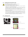
1-3 Installing the CPU and CPU Cooler
Read the following guidelines before you begin to install the CPU:
• Make sure that the motherboard supports the CPU.
(Go to GIGABYTE's website for the latest CPU support list.)
• Always turn off the computer and unplug the power cord from the power outlet before
installing the CPU to prevent hardware damage.
• Locate the pin one of the CPU. The CPU cannot be inserted if oriented incorrectly. (Or you
may locate the notches on both sides of the CPU and alignment keys on the CPU socket.)
• Apply an even and thin layer of thermal grease on the surface of the CPU.
• Do not turn on the computer if the CPU cooler is not installed, otherwise overheating and
damage of the CPU may occur.
• Set the CPU host frequency in accordance with the CPU specifications. It is not recom-
mended that the system bus frequency be set beyond hardware specifications since it
does not meet the standard requirements for the peripherals. If you wish to set the fre-
quency beyond the standard specifications, please do so according to your hardware
specifications including the CPU, graphics card, memory, hard drive, etc.
1-3-1 Installing the CPU
A. Locate the alignment keys on the motherboard CPU socket and the notches on the CPU.
NotchNotch
Alignment Key
Alignment Key
LGA 775 CPU
LGA775 CPU Socket
Pin One Corner of the CPU Socket
Triangle Pin One Marking on the CPU

GA-EG45M-UD2H Motherboard - 14 -
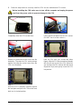
B. Follow the steps below to correctly install the CPU into the motherboard CPU socket.
Step 2:
Lift the metal load plate from the CPU socket.
(DO NOT touch socket contacts.)
Step 4:
Hold the CPU with your thumb and index
fingers. Align the CPU pin one marking (triangle)
with the pin one corner of the CPU socket (or
you may align the CPU notches with the socket
alignment keys) and gently insert the CPU
into position.
Step 3:
Remove the protective socket cover from the
load plate. (To protect the CPU socket, always
replace the protective socket cover when the
CPU is not installed.)
Step 5:
Once the CPU is properly inserted, replace
the load plate and push the CPU socket lever
back into its locked position.
Before installing the CPU, make sure to turn off the computer and unplug the power
cord from the power outlet to prevent damage to the CPU.
Step 1:
Completely raise the CPU socket lever.
CPU Socket Lever

Hardware Installation- 15 -
Use extreme care when removing the CPU cooler because the thermal grease/tape between
the CPU cooler and CPU may adhere to the CPU. Inadequately removing the CPU cooler may
damage the CPU.
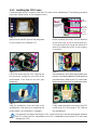
Step 3:
Place the cooler atop the CPU, aligning the
four push pins through the pin holes on the
motherboard. Push down on the push pins
diagonally.
Step 4:
You should hear a "click" when pushing down each
push pin. Check that the Male and Female push pins
are joined closely. (Refer to your CPU cooler instal-
lation manual for instructions on installing the cooler.)
Step 5:
After the installation, check the back of the
motherboard. If the push pin is inserted as the
picture above, the installation is complete.
Step 6:
Finally, attach the power connector of the CPU
cooler to the CPU fan header (CPU_FAN) on
the motherboard.
1-3-2 Installing the CPU Cooler
Follow the steps below to correctly install the CPU cooler on the motherboard. (The following procedure
uses Intel
®
boxed cooler as the example cooler.)
Step 1:
Apply an even and thin layer of thermal grease
on the surface of the installed CPU.
Step 2:
Before installing the cooler, note the direction
of the arrow sign on the male push pin.
(Turning the push pin along the direction of
arrow is to remove the cooler, on the contrary,
is to install.)
Male
Push Pin
Female
Push Pin
The Top
of Female
Push Pin
Direction of
the Arrow Sign
on the Male
Push Pin

GA-EG45M-UD2H Motherboard - 16 -
1-4 Installing the Memory
Read the following guidelines before you begin to install the memory:
• Make sure that the motherboard supports the memory. It is recommended that memory of
the same capacity, brand, speed, and chips be used.
(Go to GIGABYTE's website for the latest memory support list.)
• Always turn off the computer and unplug the power cord from the power outlet before
installing the memory to prevent hardware damage.
• Memory modules have a foolproof design. A memory module can be installed in only one
direction. If you are unable to insert the memory, switch the direction.
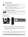
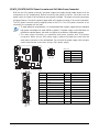
1-4-1 Dual Channel Memory Configuration
This motherboard provides four DDR2 memory sockets and supports Dual Channel
Technology. After the memory is installed, the BIOS will automatically detect the
specifications and capacity of the memory. Enabling Dual Channel memory mode
will double the original memory bandwidth.
The four DDR2 memory sockets are divided into two channels and each channel has two memory
sockets as following:
Channel 0: DDR2_1, DDR2_2
Channel 1: DDR2_3, DDR2_4
Due to chipset limitation, read the following guidelines before installing the memory in Dual Channel mode.
1. Dual Channel mode cannot be enabled if only one DDR2 memory module is installed.
2. When enabling Dual Channel mode with two or four memory modules, it is recommended that
memory of the same capacity, brand, speed, and chips be used and installed in the same
colored DDR2 sockets for optimum performance.
When memory modules of different capacity and chips are installed, a message which says
memory is operating in Flex Memory Mode will appear during the POST. Intel
®
Flex Memory
Technology offers greater flexibility to upgrade by allowing different memory sizes to be
populated and remain in Dual Channel mode/performance.
Two Modules
Four Modules
DDR2_1 DDR2_2 DDR2_3 DDR2_4
DS/SS - - DS/SS - -
- - DS/SS - - DS/SS
DS/SS DS/SS DS/SS DS/SS
Dual Channel Memory Configurations Table
(SS=Single-Sided, DS=Double-Sided, "- -"=No Memory)
DDR2_1
DDR2_2
DDR2_3
DDR2_4

Hardware Installation- 17 -
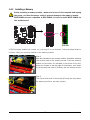
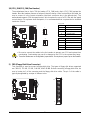
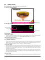
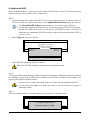
1-4-2 Installing a Memory
Step 1:
Note the orientation of the memory module. Spread the retaining
clips at both ends of the memory socket. Place the memory
module on the socket. As indicated in the picture on the left,
place your fingers on the top edge of the memory, push down
on the memory and insert it vertically into the memory socket.
Notch
DDR2 DIMM
Step 2:
The clips at both ends of the socket will snap into place when
the memory module is securely inserted.
A DDR2 memory module has a notch, so it can only fit in one direction. Follow the steps below to
correctly install your memory modules in the memory sockets.
Before installing a memory module , make sure to turn off the computer and unplug
the power cord from the power outlet to prevent damage to the memory module.
DDR2 DIMMs are not compatible to DDR DIMMs. Be sure to install DDR2 DIMMs on
this motherboard.

GA-EG45M-UD2H Motherboard - 18 -
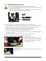
1-5 Installing an Expansion Card
Read the following guidelines before you begin to install an expansion card:
• Make sure the motherboard supports the expansion card. Carefully read the manual that
came with your expansion card.
• Always turn off the computer and unplug the power cord from the power outlet before
installing an expansion card to prevent hardware damage.
Follow the steps below to correctly install your expansion card in the expansion slot.
1. Locate an expansion slot that supports your card. Remove the metal slot cover from the chassis back panel.
2. Align the card with the slot, and press down on the card until it is fully seated in the slot.
3. Make sure the metal contacts on the card are completely inserted into the slot.
4. Secure the card's metal bracket to the chassis back panel with a screw.
5. After installing all expansion cards, replace the chassis cover(s).
6. Turn on your computer. If necessary, go to BIOS Setup to make any required BIOS changes for
your expansion card(s).
7. Install the driver provided with the expansion card in your operating system.
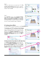
Example: Installing and Removing a PCI Express x16 Graphics Card:
• Installing a Graphics Card:
Gently push down on the top edge of the card
until it is fully inserted into the PCI Express x16
slot. Make sure the card is securely seated in
the slot and does not rock.
• Removing the Card:
Gently push back on the lever on the slot and then lift the card straight out
from the slot.
PCI Express x1 Slot
PCI Express x16 Slot
PCI Slot

Hardware Installation- 19 -
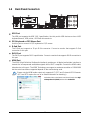
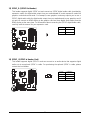
1-6 Back Panel Connectors
Please note the HDMI audio output only supports AC3, DTS and 2-channel-LPCM formats.
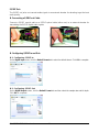
(AC3 and DTS require the use of an external decoder for decoding.)
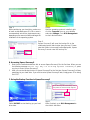
In Windows Vista, select Start>Control Panel>Sound, select Digi-
tal Output Device (HDMI) and then click Set Default.
USB Port
The USB port supports the USB 2.0/1.1 specification. Use this port for USB devices such as a USB
keyboard/mouse, USB printer, USB flash drive and etc.
PS/2 Keyboard or PS/2 Mouse Port
Use this port to connect a PS/2 keyboard or PS/2 mouse.
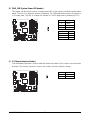
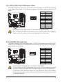
D-Sub Port
The D-Sub port supports a 15-pin D-Sub connector. Connect a monitor that supports D-Sub
connection to this port.
DVI-D Port
The DVI-D port supports DVI-D specifictation. Connect a monitor that supports DVI-D connection to
this port.
HDMI Port
The HDMI (High-Definition Multimedia Interface) provides an all-digital audio/video interface to
transmit the uncompressed audio/video signals and is HDCP compliant. Connect the HDMI audio/
video device to this port. The HDMI Technology can support a maximum resolution of 1920x1080
but the actual resolutions supported depend on the monitor being used.

GA-EG45M-UD2H Motherboard - 20 -
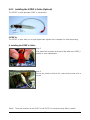
Optical S/PDIF Out Connector
This connector provides digital audio out to an external audio system that supports digital optical
audio. Before using this feature, ensure that your audio system provides an optical digital audio in
connector.
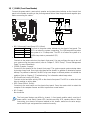
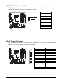
IEEE 1394a Port
The IEEE 1394 port supports the IEEE 1394a specification, featuring high speed, high bandwidth
and hotplug capabilities. Use this port for an IEEE 1394a device.
eSATA 3Gb/s Port
The eSATA 3Gb/s port conforms to SATA 3Gb/s standard and is compatible with SATA 1.5Gb/s
standard. Use the port to connect an external SATA device or a SATA port multiplier.
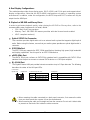
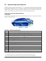
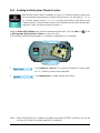
RJ-45 LAN Port
The Gigabit Ethernet LAN port provides Internet connection at up to 1 Gbps data rate. The following
describes the states of the LAN port LEDs.
Activity LED:
State Description
Blinking Data transmission or receiving is occurring
Off No data transmission or receiving is occurring
Connection/Speed LED:
State Description
Orange 1 Gbps data rate
Green 100 Mbps data rate
Off 10 Mbps data rate
Activity LED
Connection/
Speed LED
LAN Port
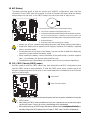
• When removing the cable connected to a back panel connector, first remove the cable
from your device and then remove it from the motherboard.
• When removing the cable, pull it straight out from the connector. Do not rock it side to side
to prevent an electrical short inside the cable connector.
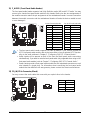
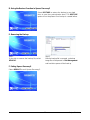
A. Dual Display Configurations:
This motherboard provides three display ports, DVI-D, HDMI, and D-Sub ports and supports dual-
display configurations. Note that the DVI-D+HDMI configuration only works in operating system
environments. In addition, under this configuration, the BIOS Setup and POST screens can only be
output from the HDMI port.
B. Playback of HD DVD and Blu-ray Discs:
In order to get better playback quality, when playing the HD DVD or Blu-ray discs, refer to the
recommended system requirements (or better) below.
• CPU: Intel
®
Dual-Core processor
• Memory: Two 1 GB DDR2 800 memory modules with dual channel mode enabled
• HDCP compliant monitor(s)
Page is loading ...
Page is loading ...
Page is loading ...
Page is loading ...
Page is loading ...
Page is loading ...
Page is loading ...
Page is loading ...
Page is loading ...
Page is loading ...
Page is loading ...
Page is loading ...
Page is loading ...
Page is loading ...
Page is loading ...
Page is loading ...
Page is loading ...
Page is loading ...
Page is loading ...
Page is loading ...
Page is loading ...
Page is loading ...
Page is loading ...
Page is loading ...
Page is loading ...
Page is loading ...
Page is loading ...
Page is loading ...
Page is loading ...
Page is loading ...
Page is loading ...
Page is loading ...
Page is loading ...
Page is loading ...
Page is loading ...
Page is loading ...
Page is loading ...
Page is loading ...
Page is loading ...
Page is loading ...
Page is loading ...
Page is loading ...
Page is loading ...
Page is loading ...
Page is loading ...
Page is loading ...
Page is loading ...
Page is loading ...
Page is loading ...
Page is loading ...
Page is loading ...
Page is loading ...
Page is loading ...
Page is loading ...
Page is loading ...
Page is loading ...
Page is loading ...
Page is loading ...
Page is loading ...
Page is loading ...
Page is loading ...
Page is loading ...
Page is loading ...
Page is loading ...
Page is loading ...
Page is loading ...
Page is loading ...
Page is loading ...
Page is loading ...
Page is loading ...
Page is loading ...
Page is loading ...
Page is loading ...
Page is loading ...
Page is loading ...
Page is loading ...
Page is loading ...
Page is loading ...
Page is loading ...
Page is loading ...
Page is loading ...
Page is loading ...
Page is loading ...
Page is loading ...
Page is loading ...
Page is loading ...
Page is loading ...
Page is loading ...
Page is loading ...
Page is loading ...
Page is loading ...
Page is loading ...
-
 1
1
-
 2
2
-
 3
3
-
 4
4
-
 5
5
-
 6
6
-
 7
7
-
 8
8
-
 9
9
-
 10
10
-
 11
11
-
 12
12
-
 13
13
-
 14
14
-
 15
15
-
 16
16
-
 17
17
-
 18
18
-
 19
19
-
 20
20
-
 21
21
-
 22
22
-
 23
23
-
 24
24
-
 25
25
-
 26
26
-
 27
27
-
 28
28
-
 29
29
-
 30
30
-
 31
31
-
 32
32
-
 33
33
-
 34
34
-
 35
35
-
 36
36
-
 37
37
-
 38
38
-
 39
39
-
 40
40
-
 41
41
-
 42
42
-
 43
43
-
 44
44
-
 45
45
-
 46
46
-
 47
47
-
 48
48
-
 49
49
-
 50
50
-
 51
51
-
 52
52
-
 53
53
-
 54
54
-
 55
55
-
 56
56
-
 57
57
-
 58
58
-
 59
59
-
 60
60
-
 61
61
-
 62
62
-
 63
63
-
 64
64
-
 65
65
-
 66
66
-
 67
67
-
 68
68
-
 69
69
-
 70
70
-
 71
71
-
 72
72
-
 73
73
-
 74
74
-
 75
75
-
 76
76
-
 77
77
-
 78
78
-
 79
79
-
 80
80
-
 81
81
-
 82
82
-
 83
83
-
 84
84
-
 85
85
-
 86
86
-
 87
87
-
 88
88
-
 89
89
-
 90
90
-
 91
91
-
 92
92
-
 93
93
-
 94
94
-
 95
95
-
 96
96
-
 97
97
-
 98
98
-
 99
99
-
 100
100
-
 101
101
-
 102
102
-
 103
103
-
 104
104
-
 105
105
-
 106
106
-
 107
107
-
 108
108
-
 109
109
-
 110
110
-
 111
111
-
 112
112


Gigabyte GA-EG45M-UD2H User manual
- Category
- Motherboards
- Type
- User manual
- This manual is also suitable for
Ask a question and I''ll find the answer in the document
Finding information in a document is now easier with AI
Related papers
-
Gigabyte GA-EG31M-S2 User manual
-
-
Gigabyte GA-EG45M-UD2H Owner's manual
-
Gigabyte GA-D525TUD User manual
-
Gigabyte GA-M68MT-S2 (rev. 1.3) User manual
-
-
-
Gigabyte GA-8ID Owner's manual
-
Gigabyte GA-EQ45M-S2 User manual
-
Gigabyte GA-MA785GPMT-UD2H Owner's manual