BSS Audio DPR-944 User manual
- Category
- DJ controllers
- Type
- User manual
This manual is also suitable for

1
DPR 944
User Manual

2
An example of this equipment has been tested and found to comply with the following European and
international Standards for Electromagnetic Compatibility and Electrical Safety:
Radiated Emissions (EU): EN55013 (1990) Associated Equipment
RF Immunity (EU): EN50082/1 (1992) RF Immunity, Fast Transients ESD
Mains Disturbance (EU): EN61000/3/2 (1995)
Electrical Safety (EU): EN60065 (1993)
Radiated Emissions (USA): FCC part 15 Class B
IMPORTANT SAFETY INFORMATION
DO NOT REMOVE COVERS. NO USER SERVICEABLE PARTS INSIDE, REFER SERVICING TO QUALIFIED
SERVICE PERSONNEL. THIS EQUIPMENT MUST BE EARTHED.
IT SHOULD NOT BE NECESSARY TO REMOVE ANY PROTECTIVE EARTH OR SIGNAL CABLE SHIELD
CONNECTIONS TO PREVENT GROUND LOOPS. ANY SUCH DISCONNECTIONS ARE OUTSIDE THE
RECOMMENDED PRACTISE OF BSS AUDIO AND WILL RENDER ANY EMC OR SAFETY CERTIFICATION
VOID.
For continued compliance with international EMC legislation ensure that all input and output cables are wired
with the cable screen connected to Pin 1 of the XLR connectors and/or the jack plug sleeve. The input XLR Pin
1 and the side-chain input jack socket sleeve are connected to the chassis via a low value capacitor, providing
high immunity from ground loops whilst ensuring good EMC performance.
V 1.0 BV/JMK 17 November 1997
Please read
We have written this manual with the aim of helping installers, sound engineers and musicians alike to get the
most out of the DPR 944. We recommend that you read this manual, particularly the section on installation,
before attempting to operate the unit.
Because of the operational nature of the DPR 944, this manual is split into three main sections. The first and
second deal with the operation and applications of the compressor and gate sections respectively, while the
third covers a more general background to use and application of the unit.
We welcome any comments or questions regarding the DPR 944 or other BSS products, and you may contact
us at the address or World Wide Web site given in the warranty section.

3
Contents
Contents
1.0 Mechanical installation 5
2.0 Unpacking 6
3.0 Mains Power Connection 6
3.1 Mains Power 6
4.0 Introduction 7
5.0 Audio Connections 10
5.1 Main Inputs 10
5.2 Main Outputs 10
5.3 Key Insert 11
6.0 Control Operations - Gate 12
6.1 Gates In 12
6.2 Key filter 12
6.3 Filter narrow 12
6.4 Key listen 13
6.5 Threshold 13
6.6 Depth 20dB 14
6.7 Attack slow 14
6.8 Release 15
6.9 Stereo link 15
6.10 Open/Shut LEDs 16
6.11 Key insert connector 16
7.0 Genereal guide to gating 17
7.1 What are gates for? 17
7.2 Basic operation 18
8.0 Application examples - Gates 20
8.1 Basic gating 20
8.2 Frequency conscious gating 20
9.0 Control Operations - Parametric
compressor 22
9.1 Comps in 22
9.2 Threshold 22

4
Contents
9.3 Ratio 23
9.4 Release fast 24
9.5 Gain 25
9.6 Side chain listen 25
9.7 Frequency 25
9.8 Width 26
9.9 Stereo link 26
9.10 Below threshold meter 27
9.11 Gain reduction meter 27
10.0 General guide to compressing 28
10.1 The need for gain control 28
10.2 Compressors & limiters 29
10.3 The effect of compression & limiting on
sound 30
10.4 Frequency selective compression 31
11.0 Application examples -
Compressors 32
11.1 Broadband (normal) compression 32
11.2 Peak limiting 32
11.3 De-essing, De-popping & reducing
proximity effect 33
11.4 Guitar treatment 35
11.5 Control of horn distortion 35
11.6 Dynamic bass and treble
enhancement 36
11.7 Using the side chain filter as EQ 36
11.8 Creative use 36
12.0 Warranty Information 37
13.0 Specifications 38
Index 40
User notes 41
Spare parts information

5
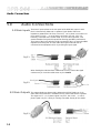
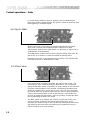
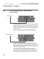
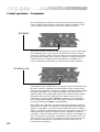
Mechanical Installation
1.0 Mechanical installation
A vertical rack space of 1U (1 3/4"/44.5mm high) is required, with a depth of
190mm, excluding connectors. Ventilation gaps are unnecessary.
If the unit is likely to undergo extreme vibration through extensive road
trucking and touring, the unit must be supported at the rear and/or sides to
lessen the stress on the front mounting flange. The necessary support can
generally be bought ready-built, as a rack tray, or the DPR 944 can be
mounted between other units. Damage caused by insufficient support is not
covered by the warranty. To prevent cosmetic damage to the front panel paint
finish, always use protective plastic cups under the rack mounting bolts.
As with any low-level signal processing electronics, it is best to avoid
mounting the DPR 944 next to a strong source of magnetic radiation or heat,
for example, a high power amplifier.
Fig 1.1 Unit dimensions.
Fig 1.2 Rack
dimensions.

6
Unpacking
2.0 Unpacking
As part of the BSS system of quality control, we check every product carefully
before packing to ensure that it reaches you in flawless condition.
Before you go any further, please check the unit for any physical damage and
retain the shipping carton and all relevant packing materials for use, should
the unit need returning.
In the event that damage has occurred, please notify your dealer
immediately, so that a written claim to cover the damages can be initiated.
Check out section 12.0; warranty section, for more info on the warranty, and
also to record your dealer details.
3.1 Mains Power
WARNING! THIS APPLIANCE MUST BE EARTHED.
The DPR 944 must always be connected to a 3-wire earthed AC outlet. The
rack framework must also be connected to the same grounding circuit. The
unit must NOT be operated unless the power cables' EARTH (ground) wire is
properly terminated - this is important for personal safety as well as for proper
control over the system grounding.
The wires in the mains lead are colour coded in accordance with the
following code.
Green and Yellow......Earth
Blue......Neutral
Brown......Live
Those units supplied to the North American market will have an integral
moulded 3 pin connector which is provided to satisfy required local standards.
IMPORTANT: The DPR 944 is designed to use 50/60Hz AC power in one of
two voltage ranges, selectable with the mains voltage selector switch on the
rear of the unit. It is vital that the position of this switch is checked BEFORE
initial power up to ensure that it matches the local mains supply. Acceptable
input AC supply voltages range from:
115V switch position 90V to 132V
230V switch position 190V to 265V
The application of voltages outside these ranges may cause permanent
damage or erratic operation of the unit, and will invalidate the warranty.
The mains fuse carrier on the rear of the unit must be fitted with the correct
type and rating of fuse, depending on the position of the mains voltage
selector switch:
115V switch position T315mA fuse
230V switch position T200mA fuse
In the unlikely event of the mains fuse failing without good reason,
DISCONNECT THE UNIT FROM THE MAINS SUPPLY, and always replace
with the appropriately rated fuse (as specified above) for continued protection
against damage and fire.
3.0 Mains Power Connection
Mains Power Connection

7
Introduction
Note: For USA and Canadian users, the replacement fuse must be of an
identical UL rated type fuse for continued compliance with safety standards.
4.0 Introduction
The BSS Audio DPR 944 is a FOUR channel unit containing two channels of
ADVANCED GATING and two channels of PARAMETRIC COMPRESSION.
Both channels of the gate may be stereo linked, as can both channels of the
compressor. At all times the gate and compressor sections operate completely
independently. Each channel has separate balanced XLR input and output
connectors. As there are no obscure gate - compressor links to accidentally
activate during a live session, operating the unit is particularly
uncomplicated.
Gating
The gate section features the unique BSS characteristic audio level control
during both attack and release phases (refer to figures 7.3 - 7.5). This ensures
the most natural sounding operation, as the normal decay characteristic of the
signal is preserved. Special circuitry is provided to reduce the possibility of
false triggering and to ensure that it is possible to use a fast attack time
without running into the problem of ‘jittering’. The provision of fully
parametric key filtering and an external key input adds to the ease of use and
flexibility of the unit.
Parametric Compression
The compressor section uses the audibly transparent ‘subtractive VCA’
technology used in all other BSS compressors, and results in substantially
better performance than other methods. The subtractive VCA also allows the
realisation of a completely different type of compression that BSS have named
PARAMETRIC COMPRESSION. This allows you to selectively compress only
certain frequencies in a signal, as selected by two conventional looking
parametric filter controls on the front panel. When the selected frequencies
are encountered, the DPR 944 starts to compress only those signals at a rate
determined by the ratio and threshold controls. This is useful for controlling a
particularly strident vocalist or brass instrument for example. There are many
uses for this type of signal processing, and they are covered in section 11.0.
If desired, the parametric filter can be ‘dialled out’, in which case the DPR
944 compressors operate over the full frequency range.

8
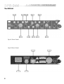
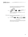
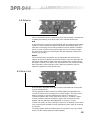
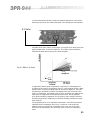
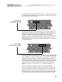
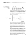
The DPR 944
Fig 4.2 Rear Panel
Fig 4.1 Front Panel

9
All numbers in bubbles refer to Section numbers.

10
5.0 Audio Connections
Audio Connections
5.1 Main Inputs
There are 2 input sockets on the rear panel of the DPR 944, Inputs 1 and 2.
Each is electronically balanced on standard 3 pin female XLRs at an
impedance greater than 10k Ohms. The ‘HOT, + or in phase’ connection is to
pin 2 and the ‘COLD, -, or out of phase’ connection is to pin 3. Pin 1 is
internally connected to the chassis earth via a low value capacitor. This
ensures freedom from ground loops whilst allowing good EMC performance.
The screen of the input cable should be connected to pin 1 to ensure that EMC
regulations are being met, and the cable shield ground should also be
connected to the equipment which is providing the input signal.
Fig 5.1
Fig 5.2
Fig 5.3
5.2 Main Outputs
The output signals are electronically balanced and fully floating on 3 pin
male XLRs. Full headroom is available into any load of 600 Ohms or greater.
The signal ‘HOT, +, or in phase’ signal is to pin 2, the ‘COLD, -, or out of
phase’ signal is to pin 3, with pin 1 being connected directly to the chassis.
When feeding the DPR 944 from unbalanced sources, connect the signal
conductor to pin 2 and the cable screen to pins 1 and 3.

11
Fig 5.4
5.3 Key Insert
Both the external key input and key send signals are available on a single
‘normalising’ TRS jack socket, wired as follows:
Fig 5.5
Inserting a plug into this socket automatically breaks the internal connection
between the side chain filter output and gate threshold input, allowing further
side chain processing, or external triggering.
When using the DPR 944 to drive unbalanced inputs, best performance is
usually obtained by connecting the DPR 944s ‘+’ signal to the equipment
signal pin and the ‘-’ signal to the equipment shield.
The DPR 944 shield should normally be connected to the equipment shield,
preferably at the equipment end.

12
Control operationsControl operations
Control operationsControl operations
Control operations
6.0 Control Operations - Gate
6.1 Gates In
When the Gates In switch is in the out, non illuminated position, all DPR 944
functions are bypassed and the input is connected directly to the output with a
high quality relay. The same condition occurs when the power is off, and
ensures that signal is passed through the unit in the case of a power or fuse
failure. When the switch is depressed, the processed signal is present on the
output.
In bypass mode (switch out), the input is still connected to the DPR 944
circuitry, so that all of the required facilities can be selected and set up prior
to operating the Gates In switch and going ‘on-air’.
6.2 Key filter
This control adjusts the centre frequency of the internal parametric key filter.
This filter is used to control the frequency content of the signal being sent to
the gate control circuitry, and allows the filtering out of signals not required to
control the gating action. The filter is not placed in the main signal path, and
therefore has no effect whatsoever on the program material passing through
the gate.
6.3 Filter narrow
Control operations - Gate

13
This switch adjusts the width of the internal key filter. This filter should be
considered as a pair of tracking high pass and low pass filters, with the space
between them controlled by this switch. With the switch out, the filter has an
approximate width of 3 octaves, but when depressed the width goes down to
approximately 0.5 of an octave. Normally it is best to start off in the wider
position, with the switch out, and then narrow down on the signal of interest,
readjusting the key filter control if required.
This type of filter not only allows band-pass configurations, but also, by the
appropriate setting of the key filter and filter narrow controls, conventional
low pass or high pass configurations. Experience will show that this approach
gives considerable operational advantages for the user over the more simple
separate low/high pass filter approach.
6.4 Key listen
When this switch is depressed, it connects the output of the key filter to the
output connector instead of the normal signal. This makes it very easy to
adjust the key filter and filter narrow controls to ‘home in’ on the signal that is
required to open the gate. This switch is latching, and may therefore be left
engaged by accident, rendering the gate function inoperable. The switch
illuminates red to warn you of this.
The filtered key signal is passed to the threshold control. The numbers around
the threshold control indicate the approximate level in dBu that will be
required from the key filter in order to just cause the gate to open.
With the control fully clockwise in the ‘out’ position, the gate will be held
closed at all times. As the control is rotated anti-clockwise, the threshold
point is progressively reduced, or becomes more sensitive. You will find that
with the filter narrow switch engaged, it is generally required to reduce the
threshold level to compensate for the smaller amount of energy being passed
from the filter.
6.5 Threshold

14
In normal use the threshold control is generally set so that wanted signal
peaks are just able to trigger the gate, this gives the maximum protection from
false triggering by undesired signals.
6.6 Depth 20dB
With the gate ‘open’, the program can pass through DPR 944 unhindered.
When ‘shut’, the level of the program passed is selected to be either
approximately -80dB with the depth switch out, effectively no signal at all, or
-20dB with the switch depressed.
The 20dB position is often used to avoid the signal sounding ‘dead’ when the
gate is shut, or to enhance or make less audible the gate dynamics.
Remember also that if a very fast attack time is desired, it will take the DPR
944 longer to open from -80dB than from -20dB.
6.7 Attack slow
Once the key level exceeds the threshold, the gate will start to open. The
time it takes to open is determined by the attack switch. For conventional
gating, the fast attack (switch out position) is usually desired to ensure that the
minimum wanted program is lost. However, unnecessarily fast attack times
should be avoided as they can produce a ‘click’. This click is not generated
by the DPR 944 but is an artifact produced by the action of quickly switching
a signal. Mechanical switches as well as fast electronic ones like the DPR
944 will all exhibit this phenomenon. If this is a problem, increase the attack
time by depressing the attack slow switch.
The attack phase, once initiated, will continue until the gate is fully open,
even if the signal momentarily falls below the threshold level. This is
important as it allows for both a clean 'chatter-free' attack phase and ensures
that, especially with short hold and release times, the gate does not try to
follow individual cycles of the program.
Control operations - Gate

15
6.8 Release
This is a dual mode control, introducing hold as well as release. The hold time
is determined internally to be about 20% of the selected release time.
Hold
A short hold time is required to avoid the DPR 944 from starting another attack
sequence if the key signal momentarily falls below the threshold level. The
hold time is reset every time an above threshold event is detected. Therefore,
if there is never a pause in the program longer than the hold time, the gate
will never shut, helping to minimise jitter (the gate repeatedly opening and
shutting very quickly).
Release
This is the final phase of operation and is entered after the hold time has
expired. At the end of the time set with the release control, the signal will be
reduced by either 80dB or 20dB as set with the depth switch. During release,
the signal is reduced, as in figure 7.3b. This produces a very natural sounding
fade, because the normal dynamics of the signal are preserved, which is
especially important for long release times.
6.9 Stereo link
With this switch depressed, both gate channels of the DPR 944 can be made
to open simultaneously.
The key signals from both channels are added together and applied to the
controls of channel 1 for processing in the normal manner. The level control
stage for channel 2 is disconnected from the channel 2 controls and
connected instead to the control signal from channel 1. Therefore, if either
channel provides a sufficiently large key signal, both channels will open
together with the gate status being displayed on channel 1's lights.
In stereo link mode, all of the controls on channel 2 are disabled. The channel
2 key insert jack still operates, and will provide key return signal for summing
to channel 1.
The main program inputs and outputs are not connected in any way in stereo
mode, only the control signals are added together.

16
6.10 Open/Shut
LEDs
If the gate is not passing program, the shut light is illuminated. If it is passing
program, the open light is illuminated.
These lights fade from one to another during the attack and release times,
their relative intensity giving a visual indication of the dynamic response of
the gating action.
One thing to remember is that during the attack and release phases, as stated
earlier, the DPR 944 uses a logarithmic control law to give a smooth fade to
the sound. When this is applied to the lights, especially for long release times,
it may appear as though nothing happens for a while. What is in reality
happening is that the sound and lights are fading, but the lights are initially
fading too slowly to be noticable.
6.11 Key insert
connector
This connector carries both the ‘key send’ and ‘key return’ signals. The key
send is a buffered version of the signal applied to the main input. It may be
used as such, or can be connected to the input of external equipment for
further processing.
The key return is the input to the DPR 944s key side chain. It may be used as
the return input from equipment being driven from the DPR 944s key send
connector, of if desired may be driven from another unrelated signal.
Refer to section 5.3 for the wiring details of this connector.
Control operations - Gate

17
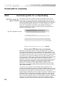
7.0 General guide to gating
7.1 What are gates
for?
Put simply, a noise gate is a device that blocks or switches off a signal, if that
signal falls below a certain preset level. This works because the ear is much
more sensitive to noise in the absence of other signals. Originally noise gates
were used for just that, gating or removing noise from recordings. For
example, traffic rumble in studios, or noise from old tape loop echo chambers.
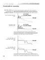
Figure 7.1 shows a pre-gated signal (input) with background noise present, and
also the user set threshold. Figure 7.2 shows the signal after being gated by a
crude gate. The background noise has been removed.
General guide to gating
Noise gates, or gates, function by taking the main input signal and splitting it
into two paths. One path passes through an electronic switch to the output and
is not modified in any other way. The other, called the key signal is processed
to provide a ‘trigger’ for the switch. Once the main signal has exceeded the
user selected threshold and provided the trigger, the gate will open. In modern
gates the switch is replaced by a fader circuit, thereby allowing the gated
signal to be faded up and down, often quite slowly. The fade up rate is
defined by an attack control, the fade down by a release control. This fading
action can be important, as the ear is much more sensitive to abrupt changes
in level than gradual ones.
One major application for modern advanced gates is the separation of sounds
so that they may be processed separately, for example in a multi-miked drum
kit. In this case each drum would have a separate microphone, the intention
being to have independent control of the level and tonal balance of each
drum. Unfortunately, due to the close proximity of the microphones, there will
be significant bleed of sound from one drum to another. Gates are used to
Fig 7.1 Noisy signal
Fig 7.2 Noisy signal
after being gated

18
prevent this. They are set up to open only when their particular drum is hit.
Unfortunately it is sometimes not easy to set a gate up to only trigger on the
desired signal, quite often the wanted and unwanted signals are close to each
other in level. This is where key filters are useful. Key filters are set up to
condition the key signal by filtering out signals that don't originate from the
drum in question, thereby increasing the difference between adjacent drums
and making the job of ensuring that only the correct drum triggers the gate
easier.
Another use for gates is in the reshaping of existing sounds. Quite often
sampled sounds will be used in recording. Sometimes these sounds may have
an inappropriate attack or release sound for their intended purpose. By
triggering a gate on the sample, and with careful setting of the attack and
release controls, a new envelope, that produced by the gate, will be imparted
to the sampled sound.
Additional features are often added to contemporary gates, for example, the
ability to trigger the gate with a signal that is not the same as the one being
gated, add enormously to the versatility of the unit and take its application
into areas far removed from the original intention of the designers of the first
‘noise gates’.
General guide to gating
7.2 Basic operation
These instructions are primarily designed to help you get started using the DPR
944.
The left hand part of the front panel is split into two identical sections, or
channels; the left hand section is referred to as gate 1, the right hand section
gate 2. There is no difference in operation between these two channels, and
so all the discussions will equally apply to both. The exception to this is when
using stereo link mode, described in section 6.9.
In operation, the gates can be considered as an automatic on-off switch that is
placed into the program signal line, with the actual operation of the switch
being controlled by the loudness level of the signal. The simplest way to
understand the basic operation is to connect one gate channel into a program
source and operate the controls whilst listening to their effect.
Having connected the input and output leads according to the instructions in
section 5.0, continue as follows:
• Make sure that all push-switches are out, in the non-illuminated position.
• Set the key filter control to 1kHz, and ensure the filter narrow switch is out.
• Set the threshold control to out, the depth and attack switches out, with the
release control about mid position.
• With the unit still in bypass mode (Gates In switch out), adjust the external
equipment to give an adequate volume level, and then operate the Gates In
switch. The signal should then be cut-off.

19
• Now gradually rotate the threshold control anti-clockwise. At some position
you will hear your signal appear - the gate has now ‘opened’. Notice also that
the green open light has come on. Spend a few minutes adjusting the
threshold control and watching the display.
• Depress the depth switch whilst listening to the program. Notice that with
the switch in, the signal does not completely disappear when the gate is
‘shut’. The most appropriate setting for this switch will depend very much on
the specific application. For general noise reduction on background
microphone clutter, the 20dB position sounds less obtrusive.
• The attack switch and release control can be intuitively operated. Attack is
the time taken for the gate to open once the threshold level has been reached.
The release is the time taken for the gate to fully close once the hold cycle
has finished. On the DPR 944, the hold time varies with the setting of the
release control, being set internally to about 20% of the selected release time.
Take some time to experiment with these controls to hear their effects on the
envelope of the program signal. Whilst doing this also observe how the gate
open and shut lights fade between each other, precisely following the sound.
You will notice that these follow the actual times set by the attack and
release controls, and is a true indication dynamically of the state of the gate.
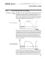
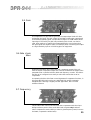
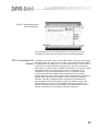
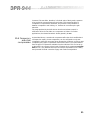
BSS use the release characteristic of figure 7.3a, the aim being to effect the
natural decay of the signal as little as possible initially, whilst providing a
rapid reduction as the signal decays toward the noise (see figure 7.3b).
Fig 7.3a&b Most
unobtrusive release -
the BSS technique
Figure 7.4a shows a compromise solution. Here the signal is reduced linearly,
but as can be seen in figure 7.4b, there is some modification of the signal.
Fig 7.4a&b
Compromise release
Figure 7.5a shows the easiest (and worst) implementation of gating. As shown
in figure 7.5b, when applied to a decaying signal, the result is an abrupt
reduction which sound unnatural.
Fig 7.5a&b Most
synthetic release
This covers the basic operation of the DPR 944. For a more detailed
description of the controls, please refer to section 6.0. For information
covering specific configurations, please see section 8.0.

20
Application examples - Gates
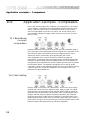
8.0 Application examples - Gates
Each of the following application examples is accompanied by a front panel
control diagram. Controls that are not highlighted should be set to the value
shown - refer to the text where no initial setting is shown. Those controls
which are highlighted can be set to any value, and are not critical to the
given example. Settings can apply to both channels, but only one is shown
here for clarity.
8.1 Basic gating
Rotate the threshold control to the out position, apply a signal to the main
input and observe that there is no output. Rotating the threshold control anti-
clockwise, you will hear the signal appear, and should see the gate lights
change state. If the signal is only allowed to briefly activate the gate, the
sound will appear 'chopped up'. Adjusting the attack and release controls will
change the nature of the sound. You may find that certain settings of these
controls never allow the gate to close.
Set the threshold so that the gate no longer opens, and now depress the depth
switch. Notice that even though the gate is shut, as confirmed by the gate
lights, you can still hear the program, although it is now 20dB quieter. This
can be useful as having the gate completely closing off the signal can impart
an unnatural character to the sound.
8.2 Frequency
conscious gating
Set the key filter control to 1kHz and the filter narrow switch to out. With a
signal applied to the main input, depress the key listen switch; you should
now hear the program. Depress the filter narrow switch and notice that the
range of the sound changes, becoming more limited.
Leave the filter narrow switch in, and now adjust the key filter control. As you
turn it anti-clockwise, the bass notes will become prominent, clockwise and
you will hear the treble.
Page is loading ...
Page is loading ...
Page is loading ...
Page is loading ...
Page is loading ...
Page is loading ...
Page is loading ...
Page is loading ...
Page is loading ...
Page is loading ...
Page is loading ...
Page is loading ...
Page is loading ...
Page is loading ...
Page is loading ...
Page is loading ...
Page is loading ...
Page is loading ...
Page is loading ...
Page is loading ...
Page is loading ...
Page is loading ...
-
 1
1
-
 2
2
-
 3
3
-
 4
4
-
 5
5
-
 6
6
-
 7
7
-
 8
8
-
 9
9
-
 10
10
-
 11
11
-
 12
12
-
 13
13
-
 14
14
-
 15
15
-
 16
16
-
 17
17
-
 18
18
-
 19
19
-
 20
20
-
 21
21
-
 22
22
-
 23
23
-
 24
24
-
 25
25
-
 26
26
-
 27
27
-
 28
28
-
 29
29
-
 30
30
-
 31
31
-
 32
32
-
 33
33
-
 34
34
-
 35
35
-
 36
36
-
 37
37
-
 38
38
-
 39
39
-
 40
40
-
 41
41
-
 42
42


BSS Audio DPR-944 User manual
- Category
- DJ controllers
- Type
- User manual
- This manual is also suitable for
Ask a question and I''ll find the answer in the document
Finding information in a document is now easier with AI
Related papers


Other documents
-
Focusrite Green 6 Quad Compressor Limiter User guide
-
-
Rolls RP252 User manual
-
Waves BSS DPR-402 Owner's manual
-
dbx 161 Owner's manual
-
Yamaha GC2020BII Owner's manual
-
-
Solid State Logic Duende Native downloads User guide
-
SoundCraft Vi 5000 Owner's manual
-
Focusrite Pro ISA 430 MkII Producer Pack User guide