Page is loading ...

05/14A EINS 516258
PLEASE READ THESE INSTRUCTIONS BEFORE SERVICING THIS APPLIANCE
680KCD C/F
780KCD C/F
Servicing
Instructions
DESN 516260 DESN 516828
For use in GB & IE
REMEMBER, when replacing a part on this appliance, use only spare parts that you can be assured conform to the
safety and performance specification that we require. Do not use reconditioned or copy parts that have not been clearly
authorised by AGA.

Contents
SECTION CONTENTS PAGE
CONSUMER PROTECTION 3
HEALTH & SAFETY 3
BENCHMARK SCHEME 4
INTRODUCTION 5
SERVICE SCHEDULE 5
BURNER REMOVAL PREPARATION 6
BURNER ACCESS 6
BURNER REMOVAL 7
CLEANING HEAT EXCHANGER CLEANING 8 - 9
CONDENSATE TRAP CLEANING 9
OVEN AND HOTPLATE FLUEWAY CLEANING 10
BURNER SERVICING INTRODUCTION 11
BURNER NOZZLE REMOVAL 12
BURNER NOZZLE REPLACEMENT 12
PHOTO ELECTRIC CELL (PEC) CLEANING 13
FAN CLEANING 13
RE-ASSEMBLE BURNER 13
OIL PUMP SERVICING INTRODUCTION 14
OIL PUMP STRAINER CLEANING 14
OIL LINE FILTER CLEANING 14
RE-COMMISSIONING BLEED AIR FROM OIL SUPPLY 15
FIT PRESSURE GAUGE 15
SWITCH ON ELECTRICITY 15
VENT OIL PUMP 15
ADJUST OIL PRESSURE 15
SET COMBUSTION AIR 16
CHECK SMOKE 16
REPLACEMENT OF PARTS FAN MOTOR 17
(BURNER) IGNITION ELECTRODES 17
IGNITOR 18
SOLENOID COIL 18
CONTROL BOX 19
PEC 19
PUMP ACCESS 20
REPLACEMENT OF PARTS ELECTRICAL COMPONENT ACCESS 21 - 22
(ELECTRICAL CONTROLS) RE-ASSEMBLE 21 - 22
CONTROL CIRCUIT - EXTERNAL 21 - 22
FAULT FINDING WIRING DIAGRAM - SATRONIC BOXES (600/700) 23
BURNER DOES NOT START 24
ERROR TABLE 25
INFORMATION SYSTEM - COOKER BURNER 26 - 27
(CONTROL BOX TYPE - DKO 970)
INFORMATION SYSTEM - COOKER BURNER 28-29
(CONTROL BOX TYPE - DKO 970N)
FAULT FINDING - BOILER 30
FAULT FINDING - COOKER 31
HIGH SMOKE NUMBERS/OIL SMELLS 32
2

Consumer Protection
As responsible manufacturers we take care to make sure that our products are designed and
constructed to meet the required safety standards when properly installed and used.
IMPORTANT NOTICE: PLEASE READ THE ACCOMPANYING WARRANTY
Any alteration that is not approved by AGA could invalidate the approval of the appliance,
operation of the warranty and could affect your statutory rights.
Health & Safety
This appliance may contain some of the materials that are indicated. It is the Users/Installers
responsibility to ensure that the necessary protective clothing is worn when handling where
applicable. The pertinent parts that contain any of the listed materials that could be interpreted
as being injurious to health and safety, see below for information.
Firebricks, Fuel Beds, Artificial Fuels
When handling use disposable gloves.
Fire cement
When handling use disposable gloves.
Glues and Sealants
Exercise caution - if these are still in liquid form use face mask and disposable gloves.
Glass Yarn, Mineral Wool, Insulation Pads, Ceramic Fibre
Maybe harmful if inhaled. May be irritating to skin, eyes, nose and throat. When handling avoid
contact with skin or eyes. Use disposable gloves, face-masks and eye protection. After handling
wash hands and other exposed parts. When disposing of the product, reduce dust with water
spray, ensure that parts are securely wrapped.
Kerosene and Gas Oil fuels (mineral oils)
1. The effect of mineral oils on the skin vary according to the duration of exposure.
2. The lighter fractions also remove the protective grease normally present on the surface of the
skin. This renders the skin dry, liable to crack and more prone to damage caused by cuts and
abrasions.
3. ‘Oil acne’ is recognised by the presence of skin rashes. The arms are most often affected,
but may occur where there is contact with oil or oily clothing.
- Seek medical attention for any rash.
- Avoid skin contact with mineral oil or clothing containing mineral oil.
4. Inhalation of mineral oil vapours must be avoided. Never fire the burner in the open air as
unburnt oil vapours are likely to occur.
5. Use a suitable barrier cream which will give protection against mineral oil, lanolin based hand
cream are usually very effective.
6. Never syphon mineral oil by mouth. If accidentally swallowed, call a doctor, do not induce
vomiting.
NOTE: SMOKE/SMELL DURING INITIAL USAGE
Some parts of the cooker have been coated with a light covering of protective oil. During initial
operation of the cooker, this may cause smoke/smell to be emitted and is normal and not a fault
with the appliance, it is therefore advisable to open doors and or windows to allow for ventilation.
Lift the lids to prevent staining the linings.
3

Benchmark places responsibilities on both manufacturers and installers. The purpose is to ensure that customers are
provided with the correct equipment for their needs, that it is installed, commissioned and serviced in accordance with the
manufacturer’s instructions by competent persons and that it meets the requirements of the appropriate Building
Regulations. The Benchmark Checklist can be used to demonstrate compliance with Building Regulations and should be
provided to the customer for future reference.
Installers are required to carry out installation, commissioning and servicing work in accordance with the Benchmark Code
of Practice which is available from the Heating and Hotwater Industry Council who manage and promote the scheme. Visit
www.centralheating.co.uk for more information.
THE BENCHMARK SCHEME
4

To ensure the best performance from your Rayburn. It
should be serviced once a year; preferably at the start of
the heating season.
This appliance must be commissioned by a competent
engineer, such as OFTEC approved.
Failure to install and maintain the appliance correctly
could lead to prosecution.
An additional flueway and combustion chamber clean
halfway through the heating season may be necessary in
some cases.
The Rayburn cannot be serviced whilst hot, so both oven
and boiler thermostats should be turned off on the
evening before the service visit.
Annual Service
During annual service flexible oil line, burner nozzles and
burner head seals MUST BE CHANGED.
WIRING: Ensure there is no damage or loose
connections. This should be carried out by a competent
engineer.
BURNER REMOVAL - for cleaning and inspection.
CLEANING - Boiler heat exchanger, flueways, oven and
hotplate flueways together with ceramic fibre burner
chambers.
BURNER SERVICING
OIL PUMP SERVICING - Cleaning of fuel line strainer.
RE-COMMISSIONING
REPLACEMENT PARTS
Oven Door Fit - Both doors must be checked and
adjusted if necessary to ensure the alignment with the
door catch is correct, the keep is secure and the oven is
sealed when the door is closed.
Additional Flueway Clean
It may be necessary in some installations to give the
boiler flueways a clean out at the end of the heating
season.
This appliance MUST be serviced at regular 12 monthly
intervals to optimise its safety, efficiency and
performance.
After servicing, complete the relevant Service Interval
Record section of the Benchmark Checklist (provided
separately).
5
INTRODUCTION SERVICE SCHEDULE

WARNING: BEFORE REMOVING SERVICE ACCESS
COVERS OR THE OIL BURNER ENSURE THAT ALL
ELECTRICAL SUPPLIES TO THE APPLIANCE HAVE
BEEN ISOLATED.
The burners can be removed without disconnecting the oil
supply pipe. However if the filters are being cleaned or a
pressure gauge fitted to the pump then the oil supply
should be turned OFF and arrangements made to catch
any oil which will leak from the oil pump.
SEE FIG. 1
1. Open up the bottom burner access door. Remove door
and put in a safe place. (Rayburn 680KCD C/F only).
2. Remove 4 inner panel securing screws and remove
panel.
3. Remove the 3 plinth securing screws and remove
plinth.
6
PREPARATION
BURNER ACCESS
Burner Removal
Fig. 1 DESN 516793

IMPORTANT: DURING BURNER REMOVAL CARE
MUST BE TAKEN NOT TO DAMAGE THE CERAMIC
FIBRE INSULATION.
SEE FIGS. 2 and 3
BOILER BURNER
1. Place a sheet on the floor in front of the cooker to act
as a working area.
2. Remove lower LH door (Rayburn 680KCD C/F only)
and burner aperture cover and store in a safe place.
3. Unscrew jubilee clip and remove flexi air intake pipe
from burner.
4. Using a 13mm spanner, remove top securing bolt and
remove burner by rotating it approximately 90°
counterclockwise and drawing it away from the boiler.
COOKER BURNER
1. Unscrew jubilee clip and remove flexi air intake.
2. Using a 13mm spanner, unscrew top securing bolt and
remove burner by rotating clockwise and drawing
away from under the cooker.
7
BURNER REMOVAL
Fig. 2
Fig. 3
DESN 515960
DESN 515961
Burner Removal

IMPORTANT DURING CLEANING CARE MUST BE
TAKEN NOT TO DAMAGE THE CERAMIC FIBRE
INSULATION.
SEE FIG. 4
1. Remove top LH door (Rayburn 680KCD C/F only)
and facia glass. Remove 2 fixing screws from control
panel chassis and hinge open.
2. Remove lower bolt from control panel fixing bracket
and pivot bracket upwards, away from boiler access
door.
SEE FIG. 5
1. Remove four securing nuts and withdraw access door
from below through burner aperture.
2. Remove stack of 5 sheet metal baffles, check
assembly and replace as shown in Fig. 8.
3. Check aluminium twisted baffles are in position and
there are 28 baffles, one in each recuperator tube.
NOTE: LH set of 4 x aluminium twisted baffles are half
length.
4. When replacing access door, tighten the 4 fixing
screws to a torque setting of 7.5 NM.
5. Check condensate trap and clean as necessary.
1. Check and clean condensate trap as necessary.
8
HEAT EXCHANGER CLEANING
Cleaning
Fig. 4 DESN 515950
Fig. 5 DESN 515949
CONDENSATE TRAP CLEANING

Cleaning
9
Fig. 6
ALL BAFFLES MUST BE STACKED IN
PLACE AS DIAGRAM ABOVE

Cleaning
SEE FIGS 7 & 8
1. Remove the top oven door (Rayburn 680KCD C/F
only) and place in a safe position.
2. Remove side and base access doors (complete with
gaskets) using hex. driver.
3. Thoroughly clean top, side and base flueways through
access apertures with brush.
4. Remove all debris with vacuum cleaner.
5. Replace side and base access doors (replace gaskets
if necessary). Secure in position using hex. driver.
6. TO REMOVE THE HOTPLATE:
Remove nut and
washer from inside the roasting oven, top left hand
side. Unscrew 2 countersunk hex. screws, insert
lifting eyes and lift hotplate out with hooks provided.
7. Brush and clean in between hotplate ribs on
underside.
8. Examine soft rope seal located around hotplate
aperture in top plate and two rope seals on hotspot.
Replace if frayed or damaged.
9. Replace hotplate ensuring the underside ribs are on
the LH side and that it seals to the top plate.
OVEN & HOTPLATE FLUEWAY
CLEANING
Fig. 7 DESN 515764
Fig. 8 - Rayburn 680KCD C/F shown DESN 516262
10

SEE FIGS. 9, 10 & 11
It is recommended that each side of the burner is serviced
individually so as not to get the components from the two
burners mixed up.
The correct combination of burner blast tubes are shown.
To remove blast tube, slacken two grub screws, pull
forward.
COOKER/BOILER = Countersunk screws in tube
COOKER
BURNER
11
INTRODUCTION
Burner Servicing
Fig. 10
10 VANES
Fig. 9
COOKER/BOILER BURNER
BOILER
BURNER
Fig. 11
4 VANES
DESN 515977
DESN 515963

SEE FIG. 12
COOKER
1. Replace two countersunk head screws and remove
blast tube, carefully feeding the HT leads through the
rear of the burner.
2. Remove two screws and slide out nozzle support
cradle complete with ignitor assembly from burner
head.
3. Unscrew nozzle from its holder with a correctly fitting
tubular spanner to avoid damage to hexagon.
BOILER
SEE FIG. 13
1. Release two countersunk head screws and remove
blast tube.
2. Remove two screws and slide out nozzle support
cradle complete with ignitor assembly from burner
head.
3. Unscrew nozzle from its holder with a correctly fitting
tubular spanner to avoid damage to hexagon.
SEE FIG. 14
1. Replace nozzle with a new one of the same make and
specification.
2. Ensure that mating faces are clean.
3. Hold nozzle holder with correct spanner when
tightening the nozzle.
4. Typically finger tight plus 1/4 turn with spanner is
sufficient.
DO NOT OVERTIGHTEN.
5. Ensure electrode gaps are correct.
12
Burner Servicing
BURNER NOZZLE REMOVAL
BURNER NOZZLE REPLACEMENT
Fig. 14
Fig. 12
DESN 510538
DESN 515965
3mm
Fig. 13

SEE FIG. 15
Withdraw Photo Electric Cell from the burner head. Clean
PEC sensing end with a soft cloth taking care not to
scratch the light sensitive body. Re-insert PEC taking care
to insert the correct way round.
Should the cell show signs of distortion or cracking,
replacement will be necessary. See PEC Replacement,
Page 19.
SEE FIG. 16
1. Remove two screws and air inlet snorkel.
2. Remove four screws and split fan case.
3. Clean between the blades of the fan impeller with a
small brush and remove any residue.
Re-assemble the burner in reverse order.
13
Burner Servicing
FAN CLEANING
PHOTO ELECTRIC CELL (PEC)
CLEANING
RE-ASSEMBLE BURNER
Fig. 15
Fig. 16
DESN 515966
COOKER/BOILER FAN

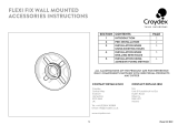
To carry out any servicing on the oil pump. Turn off the oil
line isolating valve near to the appliance.
SEE FIG. 17
1. A container must be put under the pump to catch any
oil when starting to clean the oil pump strainer.
2. Remove 4 socket head screws.
3. Remove filter.
4. Wash with clean kerosene.
5. Re-assemble in reverse order.
1. Turn OFF the line isolating valve fitted prior to the oil
line filter.
2. Follow manufacturers instructions to remove filter
element from the housing, taking care to collect
kerosene residue from the filter housing.
3. Wash filter thoroughly in clean kerosene.
4. Re-assemble in reverse order.
NOTE: Flexible fuel hose (s) must be replaced at each
service, ie annually.
14
INTRODUCTION
OIL PUMP STRAINER CLEANING
Oil Pump Servicing
OIL LINE FILTER CLEANING
Fig. 17 DESN 512002 A
COVER
STRAINER
FUEL INLET
SEAL

SEE FIG. 15
Disconnect the flexible oil pipe line at the pump inlet, open
the stop valve slowly and run off some of the oil into a
receptacle to establish an air free supply to the pump. Re-
make the connection oil tight and leave valve open.
SEE FIG. 15
Remove the bleed screw from the manifold and fit an oil
pressure gauge with R1/8 connection to check the pump
output pressure.
Set the boiler burner time clock to continuous and turn the
boiler thermostat to maximum. The boiler burner should
run on pre-purge for 7-15 seconds. With the ignition spark
energised. The oil solenoid valve should open allowing
the burner to fire.
Until all the air from the oil pump is flushed out there may
be some flame instability, resulting in the burner locking
out. This will be shown by the burner stopping and the
illumination of the signal light in the reset button of the
control box (See Fig. 18). IN THIS EVENT, WAIT AT
LEAST ONE MINUTE, then press the re-set button to
restart.
SEE FIG. 18
Whilst the burner is running, vent air from the pump by
slackening the pressure gauge port sufficiently to allow air
to bleed out. When bubble free oil seeps out, re-tighten.
SEE FIG. 19
With the burner running check the oil pressure on the
pressure gauge.
If the pressure gauge is not indicating the correct reading,
then adjust the pressure by turning the pressure regulator
clockwise to increase or anti-clockwise to decrease the
pressure until the pressure gauge reads:
BOILER - 8.5 bar (125Ibf/In
2
)
COOKER - 10 bar (145Ibf/In
2
)
15
BLEED AIR FROM OIL SUPPLY
FIT PRESSURE GAUGE
SWITCH ON ELECTRICITY
VENT OIL PUMP
ADJUST OIL PRESSURE
Re-commissioning
Fig. 18 DESN 516263
BOILER BURNER
RESET BUTTON
PRESSURE PORT
BLEED SCREW
COOKER BURNER
RESET BUTTON
DESN 515912Fig. 19
VACUUM
SUCTION
LINE
PRESSURE GAUGE
CONNECTION
PRESSURE
REGULATION

SEE FIG. 20 & 21
After 15 minutes of the boiler burner running:
1. Remove top LH door (Rayburn 680KCD C/F only),
store in a safe place.
2. Open control door.
3. Remove the plugging screw and insert the sensing
end of a portable indicator to check the CO2 (Carbon
Dioxide) level. Adjust the boiler burner air intake until a
reading of 11.0/11.5% is recorded on the indicator.
SEE FIG. 21
Remove the CO2 sampling tube and using the same hole
for flue sampling, insert the sensing end of a Baccarach
Smoke Pump and check that the smoke in the boiler
flueways does not exceed No. 2 on the scale.
Replace the plugging screw and plug.
Switch off the boiler burner.
COOKER BURNER - SEE FIG. 21
Switch on cooker burner.
After 15 minutes of the cooker burner running.
Repeat the above procedures for the cooker burner. To
sample the flue gases from the cooker burner lift up the
RH insulating cover and remove the countersunk headed
screw in the hotplate. The cooker burner should be set to
11.0/11.5% maximum Smoke No. 2.
Replace the countersunk headed screw on completion
ensuring that it will not interfere with any pots and pans
placed on the hotplate.
16
SET COMBUSTION AIR
CHECK SMOKE
Re-commissioning
Fig. 20 DESN 515955
+-
Fig. 21 - Rayburn 680KCD C/F DESN 516264

SEE FIG. 22
Follow instructions in sections BURNER ACCESS, Steps
1 to 3 and BURNER REMOVAL.
1. Isolate electric supply.
2. Remove 3-pin plug.
3. Remove solenoid plug.
4. Disconnect oil pipe.
5. Undo 2 screws and remove snorkel.
6. Remove 4 countersunk screws from fan case and split
the case.
7. Remove grub screw and withdraw fan.
8. Remove 4 countersunk screws and remove fan motor
from case.
9. Remove 3 socket head screws and withdraw pump.
10.Re-assemble in reverse order.
NOTE: Ensure that gaskets and seals are in place and in
good condition.
SEE FIG. 23
1. Release two countersunk head screws and remove
blast tube.
2. Remove two screws and slide out nozzle support
cradle c/w ignitor assembly from burner head.
3. Disconnect ignition leads.
4. Remove ignitor assembly by removing countersunk
screw and clamp.
5. Fit new ignition electrode assembly, re-assemble in
reverse order.
6. Check electrode gap and reset if necessary.
17
FAN MOTOR
Fig. 22 DESN 515970
IGNITION ELECTRODES
Replacement of parts (Burner)
Fig. 23
FAN MOTOR

SEE FIG. 24
Follow instructions in sections BURNER ACCESS, Steps
1 to 3, and BURNER REMOVAL.
1. Remove both HT leads from ignitor.
2. Remove mains plug from ignitor.
3. Remove 2 ignitor securing screws.
4. Remove ignitor.
5. Fit new ignitor, re-assemble in reverse order.
SEE FIG. 25
Follow instructions in sections BURNER ACCESS, Steps
1 to 3, and BURNER REMOVAL.
1. Remove plug.
2. Remove solenoid securing nut and washer.
3. Remove solenoid coil.
4. Fit new solenoid coil, re-assemble in reverse order.
18
Replacement of parts (Burner)
Fig. 24 DESN 516265
SOLENOID COIL
IGNITOR
Fig. 25 DESN 515972
SOLENOID

SEE FIG. 26
Follow instructions in section BURNER ACCESS, Steps 1
to 3.
1. Undo central fixing screw.
2. Gently pull control box away from base.
3. Fit new control box, re-assemble in reverse order.
SEE FIG. 27
Follow instructions in section BURNER ACCESS, Steps 1
to 3.
1. Withdraw PEC from burner head.
2. Push in retaining clip and remove PEC from plug.
3. Fit new PEC.
4. Re-attach plug and re-insert PEC taking care to insert
the correct way round.
19
Replacement of parts (Burner)
PEC
CONTROL BOX
Fig. 26
Fig. 27
DESN 515973
DESN 515974
PHOTO
ELECTRIC
CELL

SEE FIG. 28
Follow instructions in section BURNER ACCESS, Steps 1
to 3 and BURNER REMOVAL.
1. Isolate fuel supply.
2. Disconnect flexible hose (This must be replaced
annually).
3. Remove solenoid plug.
4. Remove feed pipe.
5. Slacken three securing screws and remove pump.
6. Check drive, replace if worn or damaged.
7. Replace pump, re-assemble in reverse order.
Replacement of parts (Burner)
PUMP ACCESS
Fig. 28 DESN 515976
20
PUMP
/