Page is loading ...

1
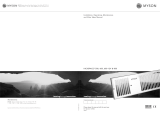
Installation & User Guide
Kitchen Plinth Heater models
KPH 1800-LV and KPH 2100-LV
Low Voltage Models
Introduction
This heater is intended to install behind the plinth in the space under the kitchen cupboards. However,
it can be installed in similar kind of application.
This unit is made for two pipe pumped central heating systems. Flow and return and pipes should be
connected as per drawing mentioned in page 2.This unit should not be installed in one pipe system.
To allow enough airflow a minimum clearance 0f 20-25mm from the top of the unit to the any shelving.
This unit must be installed of flat surface to avoid vibration.
Isolating valves (not supplied) should be fitted to both pipes (flow & return) to allow easy servicing.
The flexible hose should be fitted to both pipe (flow & return) to allow easy servicing.
This unit operate with low voltage DC power supply hence suitable to be installed in bath room or high
humid areas.
The following items should be in the carton:
DC power supply.
Flexible connecting Hoses
Fitted Grille
Fixing screws (2)
In the event of any items missing or visibly damaged, please contact us on email.

2
Installation:
1. The heater should be installed by a qualified
plumber. We recommend the use of a knee pad
when installing this product. Cut the opening in
the plinth to the size shown in the table. Use
method A or B.
Model
Width
A
Height
B*
KPH 1800 LV & 2100 LV
462mm
97mm
* The overall height of the grille is 100mm. Use
care when cutting the opening.
A
A
B
B
2. Fit isolating valves (not supplied) to the
system flow and return pipes. Failure to fit
isolating valves may mean that the product is
not serviceable in the event of failure. Remove
and discard the two protection bung in the
copper pipes and connect the flexible hoses
between system pipework and heater. Open
the isolating valves and check for leaks.
N.B. either pipe may be used on flow or return.
3. Vent air through bleed screw if
necessary.
Flate heat
screw driver
Bleed Valve
I
O
II
4. Please use the supplied DC power
supply unit to operate the fans. Power
supply should be located in right
location to comply with electrical
regulations (please consult your
electrician)
Power supply has preset at 5 V
to keep the keep the fan noise
lower.
If you prefer to run at higher
fan speed you can select 6V.
I
O
II
Fused Spur
Flow
Return

3
Commissioning:
Fault Finding:
1. Turn on the electrical supply.
2. Set the switch to l
3. Turn on the central heating system.
4. Set any room thermostat/s to maximum.
5. Set the switch to l – the fan should run and
heat will flow within a few minutes if water
temperature in the system is more than 40°C.
6. Balance the central heating system if Kitchen
plinth heater is installed on the same circuit as
panel radiators.
7. When the installation is working correctly,
remember to reset any room thermostat/s to its
normal setting
1. Fan does not run on any
switch setting.
a). Check the power supply is switched ON.
b). Check the switch has turned ON.
2. No heat output.
a). Check the power supply is switched ON.
b). If fitted, ensure any room thermostats are calling for heat.
c). Balance the central heating system if installed on same circuit
as panel radiators and increase the circulating pump speed if
required.
d). Increase the boiler water temperature.
5. Position heater, making sure the
flexible hoses is not kinked and the
electrical cable is not snagged.
Electrical Cable
Plinth
HOSE
BEND RADIUS
60mm MIN
6. Fix the heater to plinth
using fixing screw holes
located at either end of grille.
I
O
II
Grille to plinth securing
screws

4
Electrical Connections:
Only use the power supply provided with the unit.
If you need to extend the power supply cable to reach the heater unit please cut the power supply
cable at the end the cable and extend using the suitable cable. You can use the DC Jack plug to connect
into the extended cable.
Note: Please make sure the polarities are correct when you extending the cable.
Product Performance Table:
Model
Speed
Output @
75°C
( watts)
Output @
70°C
( watts)
Output @
65°C
( watts)
Output @
60°C
( watts)
Output @
55°C
( watts)
Output @
50°C
( watts)
Output @
45°C
( watts)
KPH-1800LV
Low
1611
1505
1382
1235
993
738
513
KPH-2100LV
Low
1925
1669
1472
1386
1227
1039
937
Note: Outputs are based on the running the fan at 6V DC power.
Warranty:
Products with this symbol (crossed out wheelie bin) cannot be disposed as household waste. Old electrical and electronic equipment must be recycled at a
facility capable of handling these products and their waste by-products. If you are purchasing replacement equipment your retailer may offer a 'take back'
scheme, or will be able to give details of the nearest approved authorised treatment facility. Proper recycling and waste disposal will help conserve
resources whilst preventing detrimental effects on our health and the environment.
This product is covered by a standard 12 month product replacement warranty against any manufacturing defects
or workmanship. Warranty is only for the main product not for any accessories that comes with the heater. The
manufacturer reserves the right to replace or repair the product.To extend your warranty to 24 months the product
must be registered online within 28 days from purchase date. See the warranty instruction note included for more
details.
This warranty will not cover:
Necessary maintenance and repair or replacement of parts due to normal wear and tear.
Transport costs, labour cost related to commissioning/decommissioning the product from the central heating
system.
Any damage resulting from modifications or adjustments which may be made to the product.
Thermix UK Ltd
The North Colchester Business,
340 The Crescent, Colchester, CO4 9AD
email: technical@thermix.co.uk
/