Tektronix MTM400A Technical Reference

Type
Technical Reference

This manual is also suitable for

xx
MTM400A, IPM400A, and RFM300
DTV Monitors
Specications and Performance Verication
ZZZ
Technical Reference
*P077017602*
077-0176-02
MTM400A, IPM400A, and RFM300
DTV Monitors
Specications and Performance Verication
ZZZ
Technical Reference
xx
This document applies to rmware versions 4.0 and above.
www.tektronix.com
077-0176-02
Copyright © Tektronix. All rights reserved. Licensed software products are owned by Tektronix or its subsidiaries
or suppliers, and are p rotected by national copyright laws and international treaty provisions.
Tektronix products are covered by U.S. and foreign patents, issued and pending. Information in this publication
supersedes that in all previously published material. Specications and price change privileges reserved.
TEKTRONIX and TEK are registered trademarks of Tektronix, Inc.
FlexVuPlus is a registered trademarks of Tektronix, Inc.
Contacting Tektronix
Tektronix, Inc.
14200 SW Karl Braun D rive
P.O. Box 5 0 0
Beaverton, OR 97077
USA
For product information, sales, service, and technical support:
In North America, call 1-800-833-9200.
Worldwide, visit www.tektronix.com to nd contacts in your area.
Table of Contents
General Safety Summary ......................................................................................... iv
Preface ............................................................................................................. vii
Product Documentation ..................................................................................... vii
Specicati
ons ....................................................................................................... 1
Electrical, Hardw are, and Signal Specications............................................................ 1
Power Source Characteristics................................................................................ 15
Environmental Characteristics .............................................................................. 16
Mechanical (Physical) Characteristics...................................................................... 16
Performance Verication ......................................................................................... 17
Require
ments.................................................................................................. 17
Procedure ...................................................................................................... 17
MTM400A, IPM400A, and RFM300 Specications and Performance Verication i
Table of Contents
List of Figure
s
Figure 1: DTV monitor RUI display ............................................................................ 18
ii MTM400A, IPM400A, and RFM300 Specications and Performance Verication
Table of Contents
List of Tables
Table i: Product documentation................................................................................. vii
Table 1: Rem
ote User Interface (RUI) platform characteristics............................................... 1
Table 2: TS processor card - system timing clock .............................................................. 1
Table 3: TS processor card - ASI interface ...................................................................... 1
Table 4: TS processor card - SMPTE310M interface ......... ................................................ . 2
Table 5: TS processor card - alarm connector................................................................... 3
Table 6: TS processor card - alarms.............................................................................. 4
Table 7: T
S processor card - LTC connector .................................................................... 4
Table 8: TS processor card - Ethernet RJ-45 connector........................................................ 4
Table 9: QAM Annex A interface card characteristics......................................................... 5
Table 10: QAM Annex B2 interface card characteristics ...................................................... 5
Table 11: QAM Annex B2 measurements ....................................................................... 5
Table 12: QAM Annex C interface card characteristics........................................................ 6
Table
13: 8PSK/QPSK interface card characteristics with 8PSK input ...................................... 6
Table 14: 8PSK/QPSK interface card characteristics with QPSK input...................................... 7
Table 15: 8PSK and QPSK measurements ...................................................................... 7
Table 16: DVB-S2 interface card characteristics ............................................................... 8
Table 17: DVB-S2 measurements ................................................................................ 8
Table 18: 8VSB interface card characteristics .................................................................. 9
Ta
ble 19: 8VSB measurements ................................................................................... 9
Table 20: COFDM interface card characteristics .............................................................. 11
Table 21: COFDM measurements ............................................................................... 11
Table 22: GigE interface card - general characteristics ....................................................... 13
Table 23: GigE interface card - Ethernet electrical port....................................................... 13
Table 24: GigE interface card - Ethernet Optical port......................................................... 13
Table 25: GigE interface card - ASI input...................................................................... 14
Table 26: GigE interface card - ASI output (active loopthrough of ASI/SMPTE input or TS from GigE
interface card) ................................................................................................. 14
Table 27: GigE interface card - SMPTE310M input (loopthrough to ASI output)................... ...... 15
Table 28: AC power source characteristics..................................................................... 15
Table 29: Transport stream card batteries....................................................................... 15
Table 30: Environmental characteristics ........................................................................ 16
Table 31: Mechanical characteristics............................................................................ 16
MTM400A, IPM400A, and RFM300 Specications and Performance Verication iii
General Safety Summary
General Safet
ySummary
Review the fo
llowing safety precautions to avoid injury and prevent damage to
this product or any products connected to it.
To avoid pot
ential hazards, use this product only as specied.
Only qualied personnel should perform service procedures.
To Avoid Fi
re or Personal
Injury
Use Proper Power Cord. Use only the power cord specied for this product and
certied for the country of use.
Ground the Product. This product is grounded through the grounding conductor
of the power cord. To avoid electric shock, the grounding conductor must be
connected to earth ground. Before making connections to the input or output
terminals of the product, ensure that the product is properly grounded.
Observe All Terminal Ratings. To avoid re or shock hazard, observe all ratings
and markings on the product. Consult the product manual for further ratings
information before making connections to the product.
The inputs are not rated for connection to mains or Category II, III, or IV circuits.
Power Disconnect. The power cord disconnects the product from the power source.
Donotblockthepowercord;itmustremain accessible to the user at all times.
Do Not Operate Without Covers. Do not operate this product with covers or panels
removed.
Do Not Operate With Suspected Failures. If you suspec t that there is damage to this
product, have it inspected by qualied service p ersonnel.
Avoid Exposed Circuitry. Do not touch exposed connections and components
when power is present.
Use Proper Fuse. Useonlythefusetypeandratingspecied for this product.
Do Not Operate in Wet/Damp Conditions.
Do Not Operate in an Explosive Atmosphere.
Keep Product Surfaces Clean and Dry.
Provide Proper Ventilation. Refer to the manual’s installation instructions for
details on installing the product so it has proper ventilation.
iv MTM400A, IPM400A, and RFM300 Specications and Performance Verication
General Safety Summary
Terms in this Manual
These terms may
appear in this manual:
WARNING. Warning statements identify conditions or practices that could result
in injury or loss of life.
CAUTION. Caution statements identify conditions or practices that could result in
damage to this product or other property.
Symbols and Terms on the
Product
These terms may appear on the product:
DANGER in
dicates an injury hazard immediately accessible as you read
the marking.
WARN IN G
indicates an injury hazard not immediately accessible as you
read the marking.
CAUTIO
N indicates a hazard to property including the product.
The following symbol(s) may appear on the product:
MTM400A, IPM400A, and RFM300 Specications and Performance Verication v
General Safety Summary
vi MTM400A, IPM400A, and RFM300 Specications and Performance Verication
Preface
This manual contains the following information about the MTM400A, IPM400A,
andRFM300DTVMonitors:
Specications lists the electrical, physical, and environmental specications
of the DTV monitors.
Performance Verication contains a procedure to verify that the DTV
monitors is operating normally.
Product D ocumentation
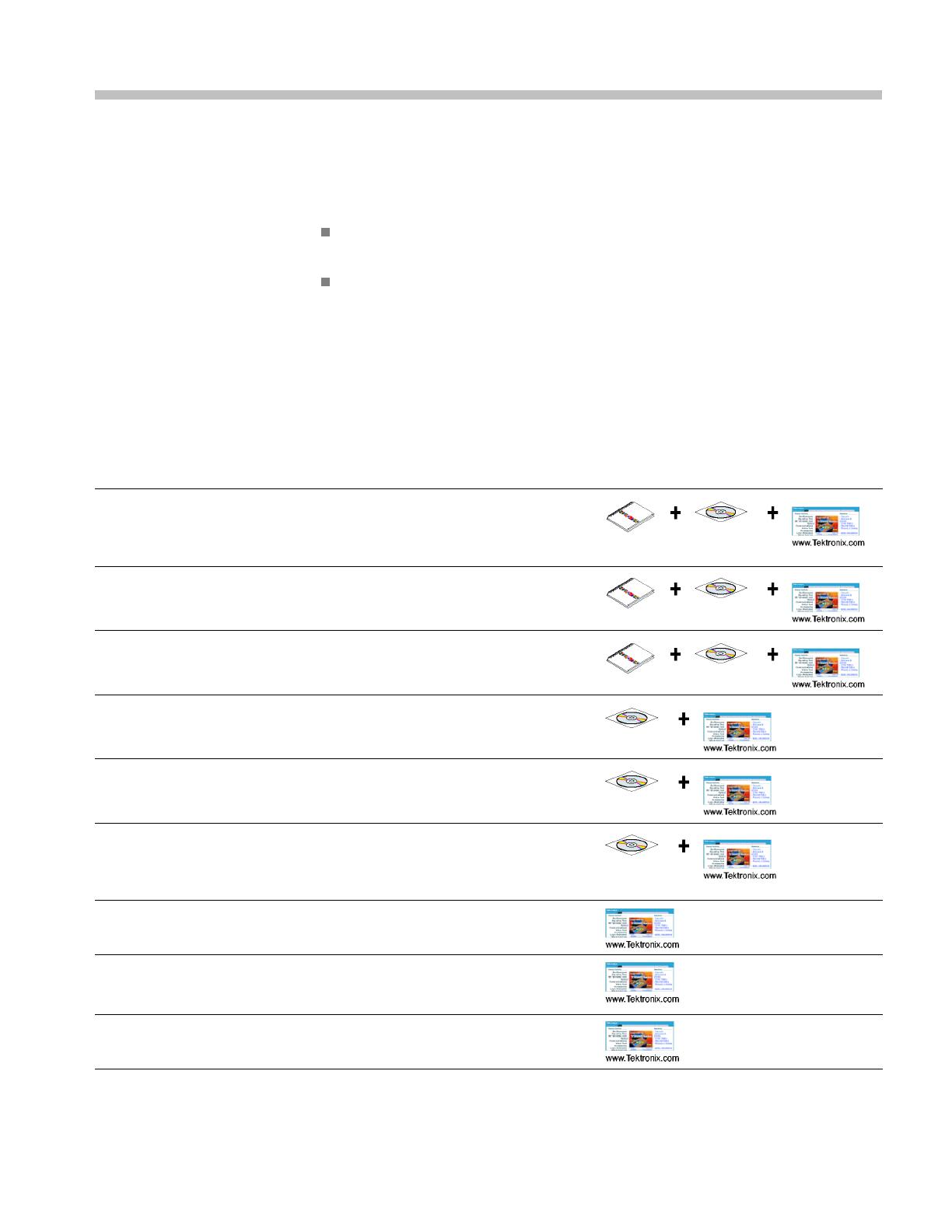
Table i lists the product documentation supporting the DTV monitor.
Table i: Product documentation
Item (Tektronix part number) Purpose Location
MTM400A DTV Monitor Quick Start
User Manual (071-2492-xx English,
071-2493-xx Japanese 071-2632-xx
German)
Provides installation and high-level
operational overviews
IPM400A DTV Monitor Quick Start User
Manual (071-2698-xx English)
Provides installation and high-level
operational overviews
RFM300 DTV Monitor Quick Start User
Manual (071-2700-xx English)
Provides installation and high-level
operational overviews
MTM400 and MTM400A RUI v3.x
Upgrade Technical Reference
(077-0174-xx)
Describes the remote user interface
(RUI) changes introduced with the
MTM400A monitor
MTM400A, IPM400A, and RFM300
Technical R eference (077-0175-xx)
Provides in-depth operating information
MTM400A, IPM400A, and RFM300
Specications and Performance
Verication Technical Reference
(077-0176-xx)
Provides complete product
specications and a procedure
for verifying the operation of the
instrument (this document)
MTM400A, IPM400A, and RFM300 Read
This First (071-2654-xx)
Describes late breaking product
information and operational issues
MTM400A, IPM400A, and RFM300
Test Parameter and Conguration File
Technical R eference (077-0177-xx)
Provides information about using test
parameters and conguration les
MTM400A, IPM400A, and RFM300
Programmer Manual (077-0178-xx)
Provides information about remote
command syntax
MTM400A, IPM400A, and RFM300 Specications and Performance Verication vii
Preface
Table i: Product documentation (cont.)
Item (Tektronix part n umber) Purpose Location
MTM400A, IPM400A, and RFM300
Declassication and Security Instructions
(077-0179-xx)
Provides instructions for removing
your proprietary information from the
instrument
MTM4UP Upgrade Instructions
(075-0973-xx)
Provides instructions for upgrading the
MTM400A DTV Monitor
IPM4UP Upgrade Instructions
(075-0997-xx)
Provides instructions for upgrading the
IPM400A DTV Monitor
RFM3UP Upgrade Instructions
(075-0993-xx)
Provides instructions for upgrading the
RFM300 DTV Monitor
viii MTM400A, IPM400A, and RFM300 Specications and Performance Verication
Specications
This section lists the electrical, environmental, and p hysical specications of
the DTV monitors. All specications are guaranteed unless labeled typical.
Typical spec
ications are provided for your convenience and are not guaranteed.
Electrical characteristics apply to test systems operating within the environmental
conditions.
Electrical, Hardware, and Signal Specications
Table 1: Remote User Interface (RUI) platform characteristics
Characteristic Description
Minimum Specication 1.2 GHz Intel Pentium Processor (Preferred: 2 GHz)
Operating System Microsoft Windows operating systems Windows 2000, Windows XP, and Windows Vista
(Recomm
ended: Windows XP Pro)
Disk Sp
ace
2GBfre
e disk space
Ethernet
10/100
-base T
Insta
lled Software
Micro
soft Internet Explorer, Version 7.0 minimum; Sun Java Runtime Environment Version
6 Update 3 minimum (1.6.0_10)
RAM
1GB
CD-ROM Drive
8x
Dis
play
1024 x 768 pixel video monitor w ith 16 bit (65000) available colors
Table 2: TS processor card - system timing clock
Characteristic Description
PCR Offset Measurement Accuracy
± 2.0 ppm
System Timing Clock Drift ± 1.0 ppm per year (maximum)
Table 3: TS processor card - ASI interface
Characteristic Description
ASI Input
Connector BNC
Transport Stream Rate
155 Mbps maximum, 250 kbps minimum
Data Format
Accepts both Burst and Packet mode ASI format
Signal Amplitude
2.0 V
p-p
maximum; 200 mV
p-p
minimum
Termination
75 nominal, transformer coupled
Return Loss 10 dB min, 5 MHz to 270 MHz
Link Rate 270 Mbaud ± 100 ppm
MTM400A, IPM400A, and RFM300 Specications and Performance Verication 1
Specications
Table 3: TS processor card - ASI interface (cont.)
Characteristic Description
ASI Output (The Output is an active loopthrough of the Input.)
Connector BNC
Impedance
75 nominal, transformer coupled
Transport Stream Rate Same as the ASI input
Signal Amplitude 1.0 V
p-p
max, 600 mV
p-p
min, into a 75 load
Return Loss 10 dB min at 270 MHz
Table 4
: TS processor card - SMPTE310M i nterface
Characteristic Description
SMPTE310M Input
Connector BNC
Termi
nation
75 , transformer coupled
Data
Format
Bi-phase coded. Compliant with SMPTE310M
Inp
ut Bit Rate
19,
392,658.5 bps ± 2.8 ppm
Sig
nal Amplitude
2.0 V
p-p
maximum, 200 mV
p-p
minimum
Return Loss 10 dB min at 20 MHz
SMPTE310M Output (The Output is an active loopthrough of the Input.)
Connector BNC
Output Bit Rate Same as the SMPTE310M input
Signal Amplitude 600 mV min, 1.0 V max, into a 75 load
Output Impedance 75 , transformer coupled
Return Loss 10 dB min at 20 MHz
2 MTM400A, IPM400A, and RFM300 Specications and Performance Verication
Specications
Table 5: TS proc
essor card - alarm connector
26-Pin, D-typ
e connector
Pin Function Description
1
DGND Ground
2 TTL02
TTL Output 2
3
DGND Ground
4 P5V 5 V
5
RL1NC
Relay 1: Normally closed contact
6
RL2NC
Relay 2: Normally closed contact
7
RL3NC
Relay 3: Normally closed contact
8
RL4NC
Relay 4: Normally closed contact
9
RL5NC
Relay 5: Normally closed contact
10
DGND Ground
11
DGND Ground
12 TTL03
TTL Output 3
13 P5V 5 V
14
RL1CC Relay 1: Common contact
15
RL2CC Relay 2: Common contact
16
RL3CC Relay 3: Common contact
17
RL4CC Relay 4: Common contact
18
RL5CC Relay 5: Common contact
19 TT
L01
TTL Output 1
2
0
DGND Ground
2
1
T
TLI1
T
TL Input 1
22
RL1NO
Relay 1: Normally open contact
23
RL2NO
Relay 2: Normally open contact
24
RL3NO
Relay 3: Normally open contact
25
RL4NO
Relay 4: Normally open contact
26
RL5NO
Relay 5: Normally open contact
Connector shell - Chassis ground
MTM400A, IPM400A, and RFM300 Specications and Performance Verication 3
Specications
Table 6: TS proc
essor card - alarms
Characteristic Value
Alarm Relay
Number of rel
ays
5
Maximum Swi
tching Current
1Amp
Maximum Swi
tch Voltage
24 V
DC
Contact Re
sistance
100 milli-
max
TTL Output
Pins of the Alarms
Output Connector
Output Type
TTL open c
ollector, requires external pull-up resistor
Logic Hi
gh Voltage
2.0 V min
Logic Low Voltage 0.8 V max, sinking 100 mA
Maximum Switching Current
100 mA
TTL Input Pins of the Alarms Output
Connec
tor
Maximum Input Voltage 5.1 V
Logic High Input Voltage 2.0 V min
Logic
Low Input Voltage
0.8 V m
ax
+5 V O
utput, Pins 4 and 13 of the
Alarms Output Connector
Output Voltage
4.9
V min, 5.1 V max, no load
Maximum Output Current
100
mA
Output Protection Fused, self resetting
Table 7: TS processor card - LTC connector
LTC 2-pin connector Pin Function Description
1IN+
2IN-
Connector shell - Chassis ground
Port Specication
Type
Linear time code, SMPTE standard to ANSI/SMPTE 12M - 1995
Input Voltage
2.0 V p-p differentially minimum
Table 8: TS processor card - Ethernet RJ-45 connector
Characteristic Description
Connector 10/100 Base-T; RJ-45 Use only good quality screened cable; Cat 6
4 MTM400A, IPM400A, and RFM300 Specications and Performance Verication
Specications
Table 9: QAM Ann
ex A interface card characteristics
Characteristic Description
Input Frequen
cy Range
51 MHz to 858 MH
z, 62.5 kHz steps
Modulation Format
16 QAM, 64 QAM
, 256 QAM (compliant with DVB-C ETS 300 421)
Modulation
Baud Rate, QAM A
5.0 Mbaud/s
minimum, 6.952 Mbaud/s maximum
Input Signa
l Level
-57 dBm (50 d
BuV) to -27 dBm (80 dBuV), with a 16, 64, and 256 QAM input, providing ve or
fewer Transport Error Flags in 10 seconds, w hich corresponds to a post FEC rate of 1e
-8
Modulation Error Ratio (with
equalizer)
38 dB min, with a 64 Q AM input and 256 QAM input
Receiver Bandwidth, Q AM A
8 MHz nominal
Input Termination Impedance
75 nominal
Input Return Loss 6 dB min, 10 dB typical, 51 MHz to 858 MHz
Loop Through Power Gain
1.5 dB to
4 dB typical, 51 MHz to 858 MHz typical
Loop Th
rough Noise Figure
8dBtyp
ical
Loop Th
rough Output Return Loss
Greate
rthan10dBtypical
Table 10: QAM A nnex B2 interface card characteristics
Characteristic Description
Input Frequency Range 88 MHz to 858 MHz
Input Signal Level -64 dBm to -19 dBm (45 dBuV to 90 dBuV relative to 75 ) (With either a 64 or 256 QAM
input, there are ve or fewer Transport Error Flags in 11 seconds, which corresponds to a post
FEC rate of 1e
-8
) -55 dBm to ensure compliance to EN 55103-2 immunity
Modulation Format
64 Q AM, 256 QAM (compliant with ITU J-83 Annex B)
Interleaving Mode Level 1 and Level 2 interleaving support compliant with all ITU J-83 Annex B, excluding I, J =
(128,7) and (128,8), and in 256 QAM excluding (8, 16) and (16, 8)
Modulation Baud Rate
64 QAM: 5.056941 Mbaud/s 256 QAM: 5.360537 Mbaud/s
Spectrum Polarity Demodulates both Normal and Inverted IF Spectrum.
Receiver Bandwidth, Q AM B
6 MHz nominal
Connector Type
Ftype
Input Termination Impedance
75 nominal
Input Return Loss 5 dB typical
Ultimate Modulation Error Ratio
with Equalizer
37 dB with equalizer; typical
Table 11: QAM Annex B2 measurements
Characteristic Description
RF Lock
RF lock is indicated by LED and Status
Input Level (Signal Strength)
(Typical)
Range: -64 dBm to -19 dBm (45 dBuV to 90 dBuV relative to 75 s)
Resolution: 1 dB
Accuracy: ± 3 dB
MTM400A, IPM400A, and RFM300 Specications and Performance Verication 5
Specications
Table 11: QAM Annex B2 measurements (cont.)
Characteristic Description
EVM (Error Vector Magnitude)
(Typical)
Display Range for 64 QAM: 1% to 5% rms
Display Range for 256 QAM: 1% to 2.5% rms
Resolution: 0.1%
Accuracy: "1%
MER (Modulation Error Ratio) with
Equalizer (Typical)
Display Range:
64 QAM: 22 dB to 37 dB
256 QAM: 28 dB to 37 dB
Resolution: 0.1 dB
Accuracy:±1dBforMER<25dB;(plus-min)3dBforMER25dBto34dB
(measured at -30 dBm input)
SNR (Signal to Noise Ratio)
(Typical)
Display Range:
64 QAM: 22 dB to 37 dB
256 QAM: 28 dB to 37 dB
Resolution: 1 dB
Accuracy: "1 dB for SNR < 25 dB; ± 3 dB for SNR 25 dB to 34 dB
BER (Bit Error Ratio) Pre-RS BER is displayed
TEF (Transport Error Flag) Transport Error Flags (uncorrectable error count) ina1secondwindow and 10 second window
are displayed.
Constellation
The RF constellation is displayed.
Table 12: QAM Annex C interface card characteristics
Characteristic Description
Input Frequency Range 88 MHz to 858 MHz, 62.5 kHz steps
Modulation Format
16 QAM, 64 QAM, 256 QAM (compliant with ITU J-83 Annex C)
Modulation Baud Rate, QAM C 4.5 Mbaud/s min; 5.5 Mbaud/s max
Input Signal Level -57 dBm (50 dBuV) to -27 dBm (80 dBuV ), with a 16, 64, and 256 QAM input, p roviding ve or
fewer Transport Error Flags in 12 seconds, which corresponds to a post F EC rate of 1e
-8
Modulation Error Ratio (with
equalizer)
38 dB typical, with a 64 QAM input
Receiver Bandwidth, Q AM C
6 MHz nominal
Input Termination Impedance
75 nominal
Input Return Loss 6 dB min, 10 dB typical, 88 MHz to 858 MHz
Table 13: 8PSK/QPSK interface card characteristics with 8PSK input
Characteristic Description
Input Frequency Range 950 MHz to 2150 MHz with 1 MHz step size
Input Signal Amplitude Range -60 dBm to -30 dBm for a CBER of <1e
-6
Modulation Format
QPSK in accordance with ETSI EN 300 421
Modulated Baud Rate 1 MBaud min, 30 MBaud max
Turbo Viterbi Values Supported 2/3, 3/4 (2.05), 3/4 (2.1), 5/6, 8/9
6 MTM400A, IPM400A, and RFM300 Specications and Performance Verication
Specications
Table 13: 8PSK/QPSK interface card characteristics with 8PSK input (cont.)
Characteristic Description
Turbo FEC
Turbo code
Connector Style
F-style
Input Termination Impedance
75 nominal
Input Return Loss 4 dB min, 950 MHz to 2050 MHz typical
LNB Supply Voltage Selectable; 13.0 V ± 1.5 V or 18.0 V (plus-min) 1.5 V, with 100 , 5 w att resistor load
LNB Supply Maximum Current
200 mA maximum
LNB 22 kHz Signaling Frequency 17.6 kHz min, 26.4 kHz max (22 kHz ± 20%)
LNB 22 kHz Signaling Amplitude 600 mV p-p with 100 load
Ultimate Modulation Error Ratio
(with equalizer)
26 dB with equalizer
Table
14: 8PSK/QPSK interface card characteristics with QPSK input
Characteristic Description
Inpu
t Frequency Range
950 M
Hz to 2150 MHz with 1 MHz step size
Inp
ut Signal Amplitude Range
-60
dBm to -30 dBm for a CBER of <1e
-6
Modulation Format
QPS
K in accordance with ETSI EN 300 421
Modulated Baud Rate 1 MBaud min, 30 MBaud max
Viterbi Values Supported 1/2, 2/3, 3/4, 5/6, 6/7, 7/8
FEC In accordance with ETSI E N 300 421
Turbo Viterbi Values Supported 1/2, 2/3, 3/4, 5/6, 7/8
Turbo FEC
Turbo code
Connector Style
F-style
Input Termination Impedance
75 nominal
Input Return Loss 4 dB min, 950 MHz to 2050 MHz typical
LNB Supply Voltage Selectable; 13.0 V ± 1.5 V or 18.0 V (plus-min) 1.5 V, with 100 , 5 w att resistor load
LNB Supply Maximum Current
200 mA maximum
LNB 22 kHz Signaling Frequency 17.6 kHz min, 26.4 kHz max (22 kHz ± 20%)
LNB 22 kHz Signaling Amplitude 600 mV p-p with 100 load
Ultimate Modulation Error Ratio
(with equalizer)
26 dB with equalizer
Table 15: 8PSK and QPSK measurements
Characteristic Description
RF Lock
RF lock is indicated by LED and Status.
Input Level (Signal Strength)
Range: -60 dBm to -30 dBm; Resolution: 1 dBm; Accuracy: ± 5 dBm; typical
MTM400A, IPM400A, and RFM300 Specications and Performance Verication 7
Specications
Table 15: 8PSK and QPSK measurements (cont.)
Characteristic Description
EVM (Error Vector Magnitude) Display Range: 4.0% to 30.0% rms;
Resolution: 0.1%;
Accuracy: ± 20% of reading; typical
MER (Modulation Error Ratio) with
Equalizer
Display Range: 10 dB to 26 dB with equalizer;
Resolution: 1 dB;
Accuracy: ± 2 dB for range 10 dB to 20 dB; typical
SNR (Signal to Noise Ratio)
Display Range: 5 dB to 35 dB; Resolution: 1 dB;
Accuracy: ± 2 dB for range from 5 dB to 30 dB; typical
Pre R eed Solomon (RS) BER (Bit
Error Rate)
Pre-RS BER is displayed.
Post RS BER and TEF (Transport
Error Flag)
Post Reed Solomon BER (TEF ratio), TEF rate, and number of Transport Error Flags (TEF
count) are displayed.
Constellation
The RF constellation is displayed.
Table 16: DVB-S2 interface card characteristics
Characteristic Description
Input Frequency Range 950 MHz to 2150 MHz with 1 MHz step size
Input Signal Amplitude Range -60 dBm to -30 dBm for a CBER of <1e
-6
Modulation Format
QPSK in accordance with DVB-S (ETSI EN 300 421)
Modulated Baud Rate 1 MBaud min, 60 MBaud max
Viterbi Values Supported DVB–S: 1/2, 2/3, 3/4, 5/6, 6/7, 7/8
DVB-S2: 1/4, 1/3, 2/5, 1/2, 3/5, 2/3, 3/4, 4/5, 5/6, 8/9, 9/10
FEC modes Viterbi and Reed-solomon in accordance with DVB-S.
LDPC (low density parity c heck) and BCH in accordance with DVB-S2.
Short and Normal FEC blocks in accordance w ith DVB-S2.
Roll Off
0.2, 0.25, 0.35
Connector Style
F-style
Input Termination Impedance
75 nominal
Input Return Loss > 6 dB min, 950 MHz to 2150 MHz typical
LNB Supply Voltage Selectable; 13.0 V ± 1.5 V or 18.0 V ± 1.5 V, with 100 , 5 watt resistor load
LNB Supply M aximum Current
200 mA maximum
LNB 22 kHz Signaling Frequency 17.6 kHz min, 26.4 kHz max (22 kHz ± 20%)
LNB 22 kHz Signaling Amplitude 800 mV p-p with 100 load
LNB Mode
DiSEqC 2 (Digital Satellite Equipment Control)
Table 17: DVB-S2 measurements
Characteristic Description
RF Lock
RF lock is indicated by LED and Status.
8 MTM400A, IPM400A, and RFM300 Specications and Performance Verication
  • Page 1 1
  • Page 2 2
  • Page 3 3
  • Page 4 4
  • Page 5 5
  • Page 6 6
  • Page 7 7
  • Page 8 8
  • Page 9 9
  • Page 10 10
  • Page 11 11
  • Page 12 12
  • Page 13 13
  • Page 14 14
  • Page 15 15
  • Page 16 16
  • Page 17 17
  • Page 18 18
  • Page 19 19
  • Page 20 20
  • Page 21 21
  • Page 22 22
  • Page 23 23
  • Page 24 24
  • Page 25 25
  • Page 26 26
  • Page 27 27
  • Page 28 28
  • Page 29 29
  • Page 30 30

Tektronix MTM400A Technical Reference

Type
Technical Reference
This manual is also suitable for

Ask a question and I''ll find the answer in the document

Finding information in a document is now easier with AI