Page is loading ...

CamilleCamilleCamille
For Your Records and
Warranty Assistance
For reference, also attach your receipt or a copy
of your receipt to the manual.
__________________________________________
Model Name
__________________________________________
Model No.
__________________________________________
Date Purchased
__________________________________________
Where Purchased
English
Français
Owner’s Guide and Installation Manual
Form M0022-01
04/06/2015
Hunter Fan Company

2
M0022-01 • 04/06/15 • Hunter Fan Company
Welcome
© 2012–2015 Hunter Fan Company
Your new Hunter
®
ceiling fan is an addition to your home or office that
will provide comfort and performance for many years. is installation
and operation manual gives you complete instructions for installing
and operating your fan.
We are proud of our work. We appreciate the opportunity to supply
you with the best ceiling fan available anywhere in the world.
Before installing your fan, for your records and warranty assistance,
record information from the carton and Hunter nameplate label
(located on the top of the fan motor housing).
Cautions and Warnings
• READ THIS ENTIRE MANUAL CAREFULLY BEFORE BEGINNING
INSTALLATION. SAVE THESE INSTRUCTIONS.
•UseonlyHunterreplacementparts.
•Toreducetheriskofpersonalinjury,attachthefandirectlytothe
support structure of the building according to these instructions,
and use only the hardware supplied.
•Toavoidpossibleelectricalshock,beforeinstallingyourfan,
disconnect the power by turning off the circuit breakers to the
outlet box and associated wall switch location. If you cannot lock
the circuit breakers in the off position, securely fasten a prominent
warning device, such as a tag, to the service panel.
•Allwiringmustbeinaccordancewithnationalandlocalelectrical
codesandANSI/NFPA70.Ifyouareunfamiliarwithwiring,usea
qualified electrician.
•Toreducetheriskofpersonalinjury,donotbendtheblade
attachment system when installing, balancing, or cleaning the fan.
Neverinsertforeignobjectsbetweenrotatingfanblades.
•Toreducetheriskofre,electricalshock,ormotordamage,donot
useasolid-statespeedcontrolwiththisfan.UseonlyHunterspeed
controls, which are solid state.
•isproductconformstoULSTD507andiscertiedtoSTDC22.2
No.113
•Washyourhandsafteryourfaninstallationiscomplete.
Table Of Contents
1•GettingReady......................6
2•InstallingtheCeilingBracket........7
3•AssemblingandHangingtheFan ...8
4•SecuringFantoSecondarySupport
System ...........................9
5•WiringtheFan .....................10
6•InstallingtheCanopy ...............11
7•AssemblingtheBlades..............12
8•CompletingYourInstallationWitha
BowlLightFixture .................13
9•OperatingandCleaningYourCeiling
Fan ...............................16
10•Troubleshooting ..................17

3
M0022-01 • 04/06/15 • Hunter Fan Company
Preparing the Fan Site
7’ Minimum
Blades to
Floor
8’ Minimum
Ceiling
Height
30” From
Wall or
Nearest
Obstruction
Step 1 - Choose the Fan Site
Properceilingfanlocationandattachmenttothebuilding
structure are essential for safety, reliable operation, maximum
efficiency, and energy savings.
Choose a fan site where:
•Noobjectcancomeincontactwiththerotatingfanbladesduring
normal operation.
•efanbladesareatleast7feetabovetheoorandtheceilingis
at least 8 feet high.
•efanbladeshavenoobstructionstoairow,suchaswallsor
posts,within30inchesofthefanbladetips.
•efanisdirectlybelowajoistorsupportbracethatwillholdthe
outlet box and the full weight of the fan.
Checklist for Existing Fan Site
If you want to use an existing fan site, complete the following checklist to determine
if the site is acceptable and safe for your new Hunter fan. If you cannot check off
every item, prepare a new fan site as described on this page.
Fan Support System
•Fan attaches directly to building structure.
•Fansupportsystemwillholdfullweightofthefanandlightkit.
Ceiling Hole
•eoutletboxclearanceholeisdirectlybelowthejoistorsupportbrace.
Outlet Box
•eoutletboxisanUL-approvedoctagonal4”x1-1/2”outletbox(orasspecied
by the support brace manufacturer).
•eoutletboxissecuredtothejoistorsupportbracebywoodscrewsandwashers
through the inner holes of outlet box.
•eouterholesoftheoutletboxarealignedwithjoistorsupportbrace.
•ebottomoftheoutletboxisrecessedaminimumof1/16”intoceiling.
Wiring
•eelectricalcableissecuredtooutletboxbyanapprovedconnector.
•Sixinchesofleadwiresextendfromoutletbox.
Ifyourexistingfansiteissuitable,skipaheadtoSection2 • Installing the Ceiling Plate.
Suitable Existing Fan Site
FanSupport
System
FanSupport
System
Wiring
OutletBox

4
M0022-01 • 04/06/15 • Hunter Fan Company
Preparing the Fan Site (continued)
CAUTION:Allwiringmustbein
accordance with national and local
electricalcodesandANSI/NFPA70.If
you are unfamiliar with wiring, use a
qualified electrician.
Steps 2 – 3
Step 4
Step 5
Step 2 - Cut the Ceiling Hole
2-1.Locatethesitefortheceilingholedirectlybelowthejoistorsupportbracethat
will hold the outlet box and fan.
2-2.Cuta4”diameterholethroughthedrywallorplasteroftheceiling.Youwilluse
the hole to install the support brace and outlet box.
Step 3 - Install a Support Brace, If Necessary
Determineifthereisaceilingjoistdirectlyabovetheceilinghole.Ifthejoististhere,
determine if it is positioned to allow you to recess the outlet box a minimum of
1/16”intotheceiling.IfNOT,installasupportbraceasfollows:
3-1.Attacha2”x4”supportbracebetweentwojoists.Positionittoallowyouto
recessthebottomoftheoutletboxaminimumof1/16”intotheceiling.
3-2.Checkthesupportbracetoensureitwillsupportthefullweightofthefanand
light kit.
Step 4 - Install the Outlet Box
4-1.ObtainaUL-approvedoctagonal4”x1-1/2”outletbox,plustwo#8x1-1/2”
wood screws and washers, available from any hardware store or electrical supply
house.
4-2.Orienttheoutletboxsothatboththeinnerandouterholesintheboxalign
withthejoistorsupportbrace.
4-3.Drillpilotholesnolargerthantheminordiameterofthewoodscrews(5/64”)
through the inner holes of the outlet box.
4-4.Attachtheoutletboxdirectlytothesupportbraceorjoistwithtwo#8x1-1/2”
wood screws and washers. e bottom of the outlet box must be recessed a
minimumof1/16”intotheceiling.
Step 5 - Prepare the Wiring
5-1.Makesurethecircuitbreakerstothefansupplylineleadsandassociatedwall
switch location are turned off . If you cannot lock the circuit breakers in the
off position, securely fasten a prominent warning device, such as a tag, to the
service panel.
5-2.readthefansupplylinethroughtheoutletboxsothatthefansupplyline
extendsatleast6”beyondthebox.
5-3.Attachthefansupplylinetotheoutletboxwithanapprovedconnector,
available at any hardware store or electrical supply house.
5-4.MakecertainthewiringmeetsallnationalandlocalstandardsandANSI/NFPA70.
Youhavenowsuccessfullypreparedyourceilingfansite.Forinstructionstoinstall
yourceilingfan,gotoyourfanmanualandcontinuewithSection2 • Installing the
Ceiling Plate.

5
M0022-01 • 04/06/15 • Hunter Fan Company
Installer’s Choice and Optional Accessories
Standard Mounting hangs from the
ceiling by a downrod (included).
Angled Mounting recommended for a
vaulted or angled ceiling
Support Brace
Standard
Mounting
Style
Ceiling
Outlet Box
Support Brace
Ceiling
Outlet Box
Angled
Mounting
Style
8
12
Understanding Mounting and Installer’s Choice®
Hunter’spatented2-positionmountingsystemprovidesyoumaximum
installationexibilityandease.YoucaninstallyourHunterfaninone
oftwoways,dependingonceilingheightandyourpreference:Standard
orAngledmounting.estepsinthismanualincludeinstructionsfor
bothInstaller’sChoicemountingmethods.
Considering Optional Accessories
ConsiderusingHunter’soptionalaccessories,includingawall-mounted
orremotespeedcontrol.Toinstallandusetheaccessories,follow
theinstructionsincludedwitheachproduct.Forquietandoptimum
performance of your Hunter fan, use only Hunter speed controls.
CAUTION: Toreducetheriskof
personalinjury,attachthefandirectly
to the support structure of the building
according to these instructions, and use
only the hardware supplied.
Forceilingshigherthan8feet,youcanpurchase
Hunterextensiondownrods.AllHunterfansuse
sturdy3/4”diameterpipetoassurestabilityand
wobble-free performance.

6
Installing Multiple Fans?
If you are installing more than
one fan, keep the fan blades and
blade irons (if applicable) in sets,
as they were shipped.
1 • Getting Ready
Toinstallaceilingfan,besureyoucandothefollowing:
•Locatetheceilingjoistorothersuitablesupportinceiling.
•Drillholesforandinstallwoodscrews.
•Identifyandconnectelectricalwires.
•Lift40pounds.
If you need help installing the fan, your Hunter fan dealer can direct
you to a licensed installer or electrician.
Gathering the Tools
Youwillneedthefollowingtoolsforinstallingthefan:
•Electricdrillwith9/64”bit
•Keyholesaw
•2’x4’supportbrace
•UL-approvedoctagonal4”x1-1/2”outletbox
•Two#8x1-1/2”woodscrewsandwashers
•Approvedconnectorforelectricalwire
•Standardscrewdriver(magnetictiprecommended)
•Phillips-headscrewdriver(magnetictiprecommended)
•Wrenchorpliers
•Ladder(heightdependentuponinstallationsite)
Checking Your Fan Parts
Carefullyunpackyourfantoavoiddamagetothefanparts.Referto
theincludedPartsGuide.Checkforanyshippingdamagetothemotor
or fan blades. If any parts are missing or damaged, contact your Hunter
dealerorcallHunterTechnicalSupportDepartmentat866-268-1936.
M0022-01•04/06/15•HunterFanCompany

7
CAUTION: Toavoidpossibleelectricalshock,beforeinstallingyourfan,
disconnect the power by turning off the circuit breakers to the outlet box
and associated wall switch location. If you cannot lock the circuit breakers
in the off position, securely fasten a prominent warning device, such as a
tag, to the service panel.
2-1. Note: e ceiling bracket may be mounted to an existing ceiling-
-fan-rated outlet box. If the outlet box is not ceiling-fan-rated,
drill two pilot holes into the wood support structure.
epilotholesshouldbe9/64”indiameterandthroughthe
outermost holes in the outlet box.
2-2.Yourfancomeswithfourneoprenenoiseisolators.Positionthe
isolators between the ceiling bracket and the ceiling by inserting
the raised areas on each isolator into the holes in the ceiling
bracket.
2-3. Aligntheslottedholesintheceilingbracketwiththepilotholes
you drilled in the wood support structure. Note: e isolators
shouldbeushagainsttheceiling.
2-4. Placeaatwasheroneachofthetwo3”woodscrewsandpass
the screws through the slotted holes in the ceiling bracket into the
pilot holes you drilled.
2-5.Tightenthescrewsintothe9/64”pilotholes;donotuselubricants
onthescrews.Donotovertighten.
FlatWasher
3”Wood
Screw
Steps 2-3 – 2-5
Step 2-2
Ceiling
Bracket
Isolator
2 • Installing the Ceiling Bracket
M0022-01•04/06/15•HunterFanCompany

8
3 • Assembling and Hanging the Fan
WARNING:Fanmayfallifnotassembledasdirectedinthese
installation instructions.
You can assemble your fan for standard or angled mounting as
shown in steps below.
3-1.Unbundlethewiresfromthefan.
3-2.Feedthewiresfromthefanthroughthedownrod.
Note:Makesureallthewiresareonthesamesideofthemetal
dowel pin inside the downrod.
3-3.Loosenthesquareheadsetscrewontheadapterinorderto
install the downrod.
3-4.Insertthedownrodintotheadapter.Tightenbyturningthe
downrodassemblyatleast4-5fullturnsuntilitstops.
Note: Whenthedownrodassemblyisfullyinstalled,2-3threads
onthepipewillstillbevisible;thisisnormal.Securely
retighten the setscrew with a wrench or pliers.
WARNING: If the setscrew is not tightened securely, the fan
may fall.
3-5.(Optional)-ewirescanbecut(shortened),butleaveat
least8”extendingfromthetopofthedownrod.
3-6.Raisethefanandplacethedownrodballintotheceilingbracket.
Steps 3-1 – 3-4
Step 3-6
Downrod
Downrod
Canopy
Ceiling
Bracket
Setscrew
Adapter
For angled ceilings, point
opening toward peak
M0022-01•04/06/15•HunterFanCompany

9
M0022-01 • 04/06/15 • Hunter Fan Company
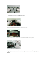
4-1.Findtheloopedendofthebraidedcableandinsertitthroughthe
ceiling plate and one of the holes in the outlet box into the ceiling.
4-2.Accessthesupportbraceintheceiling.Youmaynotbeabletodo
this from below the ceiling depending on your installation site.
4-3.Driveawoodscrewandwasherintothesideofthebracethat
holdstheoutletbox.Leave3mm(1/8”)ofspacebetweenthe
support brace and the washer.
4-4. Wrap the braided cable around the support brace once creating a
complete circle.
4-5.Hooktheloopedendofthecableoverthewoodscrewsothatthe
braided cable lies between the washer and the support brace.
4-6.Tightentheloopandsecurethescrewandwasheralltheway
down to the support brace.
4-7.Coiluptheexcesscable.
4-8.Returntothefansoyoucancompletethefanwiring.
3mm (1/8")
Steps 4-2 – 4-3
Steps 4-4 – 4-5
Steps 4-6 – 4-7
Support
Brace
Ceiling
OutletBox
Braided
Cable
4 • Securing Fan to Secondary Support System
Step 4-1

10
M0022-01 • 04/06/15 • Hunter Fan Company
All wiring must be in accordance with national and local electrical
codes and ANSI/NFPA 70. If you are unfamiliar with wiring, use a
qualified electrician.
5-1. Makesurethepowerisstilloatthebreakerbox.
5-2. Toconnectthewires,holdthebaremetalleadstogetherandplacea
wireconnectoroverthem,thentwistclockwiseuntiltight.Forallwire
connections use the wire connector provided.
5-3. Usingalarge(orange)wireconnector,connectthegreenorbare
wire (grounding) wire from the ceiling to the green with yellow
striped wire from the ceiling bracket and the green with yellow
striped wire from the downrod.
5-4.Single Switch Wiring:
Usingthelarge(orange)wireconnectors,connectthewiresfrom
thefanasfollows:
•eblackwire(ungrounded)fromtheceilingtotheblackwire
and the blue wire from the fan
•ewhitewire(grounded)fromtheceilingtothewhitewire
from the fan
5 • Wiring the Fan
F
R
O
M
C
E
I
L
I
N
G
B
R
A
C
K
E
T
F
R
O
M
F
A
N
F
R
O
M
C
E
I
L
I
N
G
Step 5-3
Step 5-4
green or bare
(grounding)
green with
yellow stripe
green with
yellow stripe
Wire
Connector
F
R
O
M
F
A
N
White
Black
(Grounded)
Blue
F
R
O
M
C
E
I
L
I
N
G
(Ungrounded)

11
5 • Wiring the Fan (continued)
6-1. Raisethecanopyovertheceilingbracketand
align the two holes of the canopy and the
ceiling bracket.
6-2.Insertandtightenthecanopyscrewssecurely.
Step 6-1
Steps 6-2
CanopyScrew
Canopy
Hanger
Bracket
Canopy
Screw
6 • Installing the Canopy
5-5. Dual Switch Wiring:
Usingthelarge(orange)wireconnectors,connectthewiresfromthe
fanasfollows:
•
e white (grounded) wire from the ceiling to the white wire from
the fan
•eblack(ungrounded)wirefromtheceilingtotheblackwire
from the fan
•esecond(ungrounded)wirefromtheceilingtothebluewire
from the fan
ATTENTION : Checkeachconnectiontomakesurenobarewire
or wire strands are visible.
5-6. Turnwireconnectorsupwardandpushthemupintotheoutletbox.
Be sure to separate the grounded wires from the ungrounded wires
inside the outlet box.
Step 5-5
11
F
R
O
M
F
A
N
White
(Ungrounded)
Black
Blue
(Grounded)
F
R
O
M
C
E
I
L
I
N
G
(Ungrounded)
M0022-01•04/06/15•HunterFanCompany

12
M0022-01 • 04/06/15 • Hunter Fan Company
Blade Assembly
Screw
Grommet
Steps 7-1 – 7-2
Step 7-1 (Detail)
7-1. Insertgrommetsintotheholesintheblades.
7-2. Installonebladeontoabladeironwiththreebladeassembly
screws.
7-3. RepeatSteps7-1–7-2untilallthreebladesareinstalled.
7 • Assembling the Blades

13
M0022-01 • 04/06/15 • Hunter Fan Company
Housing
Assembly
Screw
Shroud
Step 8-5
Step 8-4
WARNING:Useonlythelightxturesuppliedwiththisfanmodel.
8-1. Partiallyinstalltwohousingassemblyscrewsintothemounting
plate on the bottom of the fan.
8-2. Feedtheupperplugconnectorfromthemotorthroughthe
center opening of the shroud.
8-3. Slidethepartiallyinstalledscrewsthroughthekeyholeslotsinthe
shroud.Turntheshroudcounter-clockwiseuntilthescrewsare
nestled in the narrow ends of the keyhole slots.
8-4. Install a third housing assembly screw into the remaining screw
holeintheshroud.Securelytightenallthreescrews.
8-5. Installsix#6-32machinescrewsintotheouterholesintheshroud.
8 • Completing Your Installation With a Bowl Light Fixture

14
M0022-01 • 04/06/15 • Hunter Fan Company
Housing
Assembly
Screw
8-6. Connecttheupperplugconnectorfromthefantothelowerplug
connector in the light fixture.
Note: Both plug connectors are polarized and will only fit together
oneway.Makesuretheconnectorsareproperlyalignedbefore
connecting them. Incorrect connection could cause improper
operation and damage to the product.
8-7. Partiallyinstalltwohousingassemblyscrewsintotheshroud.
8-8. Slidethekeyholeslotsinthelightxtureintothepartially
installedscrews.Turnthelightkitcounter-clockwiseuntilthe
screws are nestled in the narrow ends of the keyhole slots.
8-9. Install a third housing assembly screw into the remaining screw
holeinthelightxture.Securelytightenallthreescrews.
CAUTION:Makesuretheshroudissecurelyattachedtothe
switchhousingmountingplate.Failuretoproperlyattachand
tighten all three assembly screws could result in the switch housing
and light fixture falling.
Step 8-7
8 • Completing Your Installation With a Bowl Light Fixture (Continued)
Note: IncompliancewithCanadianfederalenergy
regulations, this ceiling fan contains a device that restricts
itslightoutput.Exceedingthewattagelimitmarkedon
theMAXwattagestickeraxedtothelightsocket(s)may
result in fire hazard or improper operation.

15
M0022-01 • 04/06/15 • Hunter Fan Company
Breakaway
Connector
Steps 8-10 – 8-11
Step 8-10
8 • Completing Your Installation With a Bowl Light Fixture (Continued)
8-10.Installtheincludedbulbs(40Wmax).
8-11.Holdtheglassbowlupsoittsintheshroud.
8-12.Holdthecoverplateuptothebottomoftheglass
bowl and secure them both by screwing the finial into
the threaded rod on the bottom of the light fixture.
8-13.Attachtheextrapullchainswithpendants(included)
to the light and fan pull chains using the breakaway
connector. (You may find the breakaway connector
on the end of the extra chains.)

16
M0022-01 • 04/06/15 • Hunter Fan Company
In warm weather, use
downward air ow pattern
In cold weather, use upward
air ow pattern
To Change Airflow Direction
Turnthefanoandletitcometoacompletestop.
Unscrewthecapatthebottomoftheglassglobe
andremovethecap,nial,andglassshade.Slidethe
reversing switch on the fan to the opposite position.
Afterreinstallingglass,nial,andcap,restartfan.
Reversing
Switch
9 • Operating and Cleaning Your Ceiling Fan
9-1. Turnonelectricalpowertothefan.
9-2. efanpullchaincontrolsthespeed:fromhightoo.
elightpullchaincontrolsthelightxture:onando.
9-3. Ceilingfansworkbestbyblowingairdownward
(counterclockwise blade rotation) in warm weather to cool the
room with a direct breeze. In winter, having the fan draw air
upward (clockwise blade rotation) will distribute the warmer air
trapped at the ceiling around the room without causing a draft.
9-4. Forcleaningnishes,useasoftbrushorlint-freeclothto
preventscratching.Avacuumcleanerbrushnozzlecanremove
heavierdust.Removesurfacesmudgesoraccumulateddirtand
dust using a mild detergent and a slightly dampened cloth. You
may use an artistic agent, but never abrasive cleaning agents as
they will damage the finish.
9-5. Cleanwoodnishbladeswithafurniturepolishingcloth.
Occasionally,applyalightcoatoffurniturepolishforadded
protectionandbeauty.Cleanpaintedandhigh-glossbladesin
the same manner as the fan finish.

17
M0022-01 • 04/06/15 • Hunter Fan Company
Problem: Nothing happens; fan does not move
1.Turnpoweron,replacefuse,orresetbreaker.
2.Loosencanopy,checkallconnectionsaccordingtothewiringthefansection.
3.Checktheplugconnectionintheswitchhousing.
4.Pushmotorreversingswitchrmlyleftorrighttoensurethattheswitchisengaged.
5.Pullthepullchaintoensureitison.
6.Removetheshippingbumpers.
Problem: Noisy operation
1.Tightenthebladeassemblyscrewsandbladeironarmaturescrewsuntilsnug.
2.Checktoseeifthebladeiscracked.Ifso,replacealltheblades.
Problem: Excessive wobbling
1.Makesurethebladesaresecurelyattachedtothebladeironsaccordingtothebladeassemblyinstructions
provided.
2.Afterthoroughlyverifyingthebladesaresecurelyattachedtothebladeirons,followtheinstructionsinthe
enclosed balancing kit to balance the fan.
3.Turnpowero,supportfanverycarefully,andcheckthatthehangerballisproperlyseated.
Problem: Lights shut off suddenly, but fan is still operating
1.Checktomakesurethewattageandtypeofthelightbulbsthatareinstalledmeetthespecicationsonthe
light socket.
2.Turnthepowertothefanoatthewallswitch.Wait5minutes,thenresumepowertothefan.
If you need parts or service assistance, please call
866-268-1936orvisitusatourwebsiteat
http://www.HunterFan.com.
HunterFanCompany
7130GoodlettFarmsParkway#400
Memphis,Tennessee38016
10 • Troubleshooting
/