Page is loading ...

A.E.B. INDUSTRIALE s.r.l.
Via Brodolini, 8 - 40056 Crespellano (Bo) - ITALIA
Tel. + 39 051 969870 - Fax. + 39 051 969725
Internet: www.dbtechnologies.com
E-mail: [email protected]
MANUALE d’USO
USER MANUAL
Made in Italy
REV 4.0 Codice 420120193
DRK 20
Digital Vertical ArrayDigital Vertical Array
BEDIENUNGSANLEITUNG
CARACTERISTIQUES TECHNIQUES

INSTALLATION
DRK 20
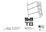
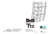
The DRK 20 flybar system and its rigging systems used for DVA T4, DVA T8, DVA T12,
DVA S09dp, DVA S10dp, DVA S1518N e DVA S2585N speakers is designed and verified
by tests in accordance with safety requirements documents, Italian Ministerial Decree DM
of 14.01.2008 "New technical standards for construction" and "Eurocode 1" and Eurocode
3 " with regard to steel structures.
The system are technically tested and certified to comply with the maximum load declared
by Certificate of Compliance issued by CERMET n.reg. PA 68913 V 00001 2011.
The DRK 20 must be used only by qualified persons!
For correct use it is necessary to observe the following guidelines:
a) Maximum load allowed depends on the position of the point of attachment of the
lifting hook (see Figure A)
b) Maximum inclination angle (allowance + / - 5 °).
c) Ensure that all connections and fixing pins are made correctly.
d) Use only original parts of dBTechnologies
The structural calculations certify that maximum weight applicable to the flybar DRK20
depends on the attachment point of the lifting hook.
5
4
6
2
1
3
11
10
12
8
7
9
17
16
18
14
13
15
22
20
19
21
1200Kg
(12KN)
1000Kg
(10KN)
1300Kg
(13KN)
750Kg
(7.5KN)
Lifting hook Maximun
position load
1 - 9 1200kg
9 - 13 1300kg
13 - 16 1000kg
16 - 22 750kg
Figure A
LIFTING HOOK
WARNING! with particular attention the maximum load of point of attachment
of the lifting hook. Failure to comply with all warnings may cause danger of structure
and content falling with potential damage to people, things and animals.
Observe
!
91
22
12
20
81
1716
51
14
13
12
8
11
01
9
7
65
4
3
2
1
RKD -20
Rgn F migig rae
auma itMx im Lod:6 00Kg Depending on pick point posion
Mauac
t Yar2 01nf ure
e 1
uThe system ms tbe assembled by qulie d person only!
aif
19
22
12
20
18
1716
15
14
13
12
8
11
01
9
7
65
4
3
2
1
RK0D -2
Rigin g ra
mg F e
mL :60 Ddg i p onMaximu o ad 0 Kg epenin o npckoi ntpsi tio
Mnu act e e 201af urYar 1
b sTh
e systemmust e asseble d by qalifed p
eron on
ly! m
u i
Always use the double pins to fix
lifting hook provided.
6
5
EnglishEnglishEnglish
user manualuser manual
EnglishEnglishEnglish
user manualuser manual
DVA T12 configuration (example 1 - 10 speakers)
Reference weight of the single DVA T12 = 30Kg (66lbs.)
Reference weight of the DRK 20 flybar = 19Kg (42lbs.)
Refer to table 1 to determine the total weight borne by flybar according to following
configuration
Quantity Weight
[kg] [lbs.]
1 30 66
2 60 132
3 90 198
4 120 264
5 150 330
6 180 396
7 210 462
Table1 8 240 528
9 270 594
10 300 660
5
4
6
2
1
3
11
10
12
8
7
9
17
16
18
14
13
15
22
20
19
21
DVA T12 configuration (example 2 - 20 speakers)
Reference weight of the single DVA T12 = 30Kg (66lbs.)
Reference weight of the DRK 20 flybar = 19Kg (42lbs.)
Refer to table 2 to determine the total weight borne by flybar according to following
configuration
Quantity Weight
[kg] [lbs.]
1 30 66
2 60 132
3 90 198
4 120 264
5 150 330
6 180 396
7 210 462
8 240 528
9 270 594
10 300 660
11 330 720
12 360 792
13 390 858
14 420 924
15 450 990
16 480 1056
17 510 1122
18 540 1188
Table 2 19 570 1254
20 600 1320
5
4
6
2
1
3
11
10
12
8
7
9
17
16
18
14
13
15
22
20
19
21
!

Mixed configuration with DVA T4 and DVA T12
The modular structure of DVA System permits mixed suspension configuration between
DVA T4 and DVA T12. For this reason, it is necessary to calculate the total weight.
Consider that one DVA T12 hanging corresponds, in weght terms, to two DVA T4.
Example:
Quantity Weight x qty Configuration weight
DVA T12 10 300Kg
DVA T4 6 90Kg
390Kg
Mixed configuration with DVA T12 and DVA S09dp
The modular structure of DVA System permits mixed suspension configuration between
DVA T12 and DVA S09dp. For this reason, it is necessary to calculate the total weight.
Example:
Quantity Weight x qty Configuration weight
DVA T12 20 600Kg
DVA S10dp 4 184Kg
784Kg
Mixed configuration with DVA T12 and DVA S10dp
The modular structure of DVA System permits mixed suspension configuration between
DVA T12 and DVA S10dp. For this reason, it is necessary to calculate the total weight.
Example:
Quantity Weight x qty Configuration weight
DVA T12 14 420Kg
DVA S09dp 4 152Kg
572Kg
5
4
6
2
1
3
11
10
12
8
7
9
17
16
18
14
13
15
22
20
19
21
5
4
6
2
1
3
11
10
12
8
7
9
17
16
18
14
13
15
22
20
19
21
Note : It is not possible use the system
from 16 to 22 points
8
Structural modification of DRK 20 flybar
Original parts dB Technologies
Note
Initiation and Operation
It is prohibited to make any changes to the structure of the DRK 20 flybar and on the stirrups
assembling of the speakers.
Tampering and/or modify the structure or the accessories may be causes risk of failure or
breakage.
It is forbidden to use parts and accessories other than those supplied.
Use only dB Technologies original parts.
Always install parts in accordance with these installation instruction!
Compile and store all DVA system documents in a safe place!
Warning
dB Technologies is not responsible for any possible damage to people, things and
animals if the security norms and total weight calculations are not observed!
During installation ensure that carrying structure of the system has added in the total weight
also the DRK 20 flybar weight, chain hoists, motors, cables and further weights.
§ 39, VBG 9a of the German employers' liability insurance association's accident prevention
regulations requires that load-carrying equipment be inspected by a qualified expert and
possible defects be eliminated prior to initial commissioning by the recipient.
§ 41 VBG 9a requires that load-carrying equipment be subjected to a non-routine inspection
following damage, repair work and other incidents that can affect load-carrying capacity.
Warning
The safety regulations might be different in other countries. Please check with your
national safety authority the valid regulations!
7
EnglishEnglishEnglish
user manualuser manual
EnglishEnglishEnglish
user manualuser manual
DVA T4
DVA T12
DVA T4
DVA S10dp
DVA T4
DVA S09dp
!
!
!
DVA Composer Acoustical Simulation and aiming for DVA Systems
DVA Composer is a 2D software for aiming and simulating acoustical response of all line
arrays and Subwoofers from DVA Series.
The software allows you to set up a stereo system composed by tops and subs, and
simulates separately the acoustical response of both.
DVA Composer also gives to the user all the information about phase alignment between
flown systems and ground stacked subwoofers, as well as it suggests an optimized
aiming of the line arrays modules and their suggested EQ presets, in order to guarantee
maximum performances even for non-expert customers.
It is recommended to download DVA_Composer free software directly from
dB Technologies (www.dbtechnologies.com) in the special section «Software
& Controller»
DOWNLOAD

SET-UP EXAMPLES
N 10°OF BOXES:
STRAIGHT
from 0° to 1,5°
from 8° to 10°
CURVED
CONFIGURATION SYSTEM
E
G
A
R
E
V
O
C
set-up 8
from 0° to 1,5°
from 3° to 10°
from 0° to 1,5°
from 3° to 10°
*
from 3° to 6°
from 8° to 10°
NUMBER
OF BOXES
STRAIGHT
CURVED
STRAIGHT
CURVED
STRAIGHT
MID
CURVED
CURVED
ANGLES
FROM 9 TO 12
FROM 6 TO 8
FROM 4 TO 5
SHAPE
EQU
SET
33
22
55
44
88
77
66
from 0° to 1,5°
*
*
set-up 2
set-up 2
set-up 3
set-up 3
N 4°OF BOXES:
STRAIGHT
from 0° to 1,5°
from 3° to 10°
CURVED
from 3° to 6°
MID CURVED
set-up 8
set-up 7
set-up 7
set-up 7
set-up 6
set-up 6
set-up 6
set-up 6
set-up 6
STRAIGHT
from 0° to 1,5°
from 3° to 10°
CURVED
DVA T12 QUICK CONFIGURATIONS
Flat Response
Front Field
RESPONSE
CURVE
NAME
11
00
EQU
SET
18
17
Angolo di inclinazione massimo ammesso del DRK20 (telaio rigging) + / - 5 °.
!
Max +5°
Max -5°
!

19
20
DRK 20 accessorio
Accessory DRK 20
Appeso
Hanging on
INSTALLAZIONE INSTALLATION
INSTALLATIONEN INSTALLATIONS
Phase 1
Phase 2
Phase 4
Phase 6
Phase 5
Phase 8
Phase 9
Phase 7
Phase 10
Phase 3
Appeso
Hanging on
INCLINAZIONE INCLINATION
NEIGUNG INCLINAISON
3°
0°
6°
10°
8°
4.5°
1.5°
DVA T12
10°
8°
6°

DRK 20 accessorio
Accessory DRK 20
INSTALLAZIONE INSTALLATION
INSTALLATIONEN INSTALLATIONS
In appoggio
Ground stacking
Phase 1
Phase 2
Phase 7
Phase 8
°
0
°
0
°
5
°
5
°
, 5
2
G U
E
O
S
AC
K
DR T N
D
O
E
N
L
U
Y
S
°
,
5
2
,
2- °
5
°
-
,
5
2
-
,5
7
° ,5
7
°-
5
-
°
-
°
5
°
, 57
°
, 5
7
Phase 3
Phase 4
Phase 5
Phase 6
2
1
2
2
2
Phase 9
Phase 10
0°0° 0°0°
5°5° 5°5°
2,5°2,5°
GROUND STACKED
USE ONLY
GROUND STACKED
USE ONLY
2,5°2,5°
-2,5°-2,5° -2,5°-2,5°
-7,5°-7,5° -7,5°-7,5°
-5°-5° -5°-5°
INCLINAZIONE INCLINATION
NEIGUNG INCLINAISON
3°
0°
6°
10°
8°
4.5°
1.5°
DVA T12
1
1
2
2
2
2
°0
0°
°
5
5°
2, °5
GR
O
UN
D T E
AC
KDS
E ONL
U
S Y
,5
2
°
- ,5°
2
,-
5
°2
5
7 °
- ,
7
-
,5°
-5°
5- °
5
°7,
7,5°
°0
0°
°
5
5°
2,5°
DGR
O
UN T K
E
SA C
D
E
ONL U
S Y
,5°
2
-
,5
2 °
,5°-
2
5
7 °
- ,
7
- ,5°
5- °
5- °
5°7,
7,
5°
Pins per bloccaggio
Fixing pins
Quick Release Pin
Staffa di fissaggio posteriore
Rear stirrup fixing
Staffa di fissaggio anteriore
Front stirrup fixing
21
22
/