Page is loading ...

A.E.B. INDUSTRIALE s.r.l.
Via Brodolini, 8 - 40056 Crespellano (Bo) - ITALIA
Tel. + 39 051 969870 - Fax. + 39 051 969725
Internet: www.dbtechnologies.com
E-mail: [email protected]
Made in Italy
COD. 420120203 Rev 2.0
Digital Vertical ArrayDigital Vertical Array
T8
MANUALE D’USO - Sezione 1
USER MANUAL - Section 1
BEDIENUNGSANLEITUNG - Abschnitt 1
CARACTERISTIQUES TECHNIQUES - Section 1

DESCRIPTION
The DVA T8 is equipped with three class D amplifiers of DIGIPRO® G2 series, high
efficiency, which delivers high output power in a compact size and low weight. Thanks to
its high efficiency the cooling of the amplifier module is obtained statically, thus avoiding
the use of a fan.
®
The power supply circuits of the DIGIPRO G2 amplifier has been conceived to work in
full-range mode; thanks to the SMPS (Switched-Mode Power Supplies) technology with
PFC (Power Factor Correction) the operation with supply voltages between 100 Vac and
240Vac is guaranteed by ensuring the same sound performances even with floating and
non-stabilized power supply systems.
The amplifier module is able to deliver 350W (RMS) for the bass section, 175W (RMS) for
the mid-section and 175W (RMS) for the treble section.
The bass section controls a 8"
neodymium woofer (2.5" voice coil)
guarantees a high SPL and the
obtainment of frequencies of up to 70Hz.
The mid-section controls one 6.5"
neodymium midranges (2" voice coil),
enclosed in its own acoustic chamber
and horn loaded with a power factor
corrector. The plug phases located in
front of the cones prevent the vertical
phases from overlapping, creating in fact
a local array with 3 output slot that
increases directivity. The horn design
was specifically created to couple it
correctly with the DVA T4 and DVA T12
modules.
The treble section controls two 1"
neodymium drivers (1.4" voice coil)
positioned vertically and spaced to
optimize the vertical cover. The horn
design was specifically created to couple
it correctly with the DVA T4 and DVA T12
modules.
EnglishEnglishEnglish
user manualuser manual
12
Modifiche strutturali alla supporto flybar
Accessori originali dBTechnologies
Inizio e funzionamento
E’ vietato apportare qualunque modifica alla struttura del flybar e relative staffe a corredo
dei diffusori stessi.
Manomettere e/o modificare la struttura o gli accessori a corredo può provocare pericolo
di cedimenti o rottura.
E’ vietato utilizzare parti e accessori diversi da quelli forniti a corredo.
Utilizzare solo parti originali fornite da dBTechnologies.
Ogni installazione ed utilizzo delle parti fornite deve essere eseguito in accordo alle
istruzioni di montaggio a corredo.
Conservare ed archiviare tutti i documenti del sistema DVA in un posto sicuro!
Attenzione
La dB Technologies non può essere ritenuta responsabile di danne a persone, a
cose ed animali nel caso in cui le prescrizioni di sicurezza e i calcoli dei pesi massimi
non siano rispettati!
Note
Durante le installazioni accertarsi che nella struttura portante del sistema vengano inclusi
nel calcolo dei pesi totali anche il peso del flybar, delle catene dei sollevatori, dei motori,
dei cavi e ulteriori pesi aggiuntivi.
§ 39, VBG 9a sull'assicurazione obbligatoria da parte datori di lavoro Tedeschi per la
prevenzione degli incidenti richiede che l'equipaggiamento del carico-portante debba
essere ispezionato da personale qualificato ed i possibili difetti debbano essere eliminati
prima della consegna al utente finale.
§ 41 VBG 9a richiede che l'equipaggiamento del carico-portante debba essere soggetto a
una manutenzione non ordinaria successivamente a danni, riparazioni e altri incidenti che
possono avere effetto sulla capacità del carico-portante.
Attenzione
Le normative sulla sicurezza possono essere diverse in funzione del paese di
destinazione. L’utilizzatore è tenuto a verificare le regolamentazioni e le leggi
cogenti in materia di sicurezza nel paese in cui utilizza il prodotto!
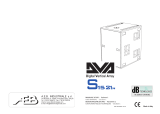
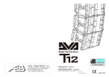
DVA T8
DVA T12
DVA T8
DVA S1518N
!
!
ItalianoItalianoItaliano
Manuale d’usoManuale d’uso
11

EnglishEnglishEnglish
user manualuser manual
14
user manualuser manual
EnglishEnglishEnglish
13
This specific design has made it possible to obtain a constant and precise 100° coverage
in a horizontal direction and 15° coverage in a vertical director for each diffuser.
CONTROLS AND FUNCTIONS
"Balanced Audio" section
1) " INPUT” INPUT CONNECTOR
Balanced input at line level. It is able to accept “XLR” sockets.
2) "LINK” OUTPUT CONNECTOR
The “XLR” connector connected in parallel with input (1) can be used to send the
input audio signal to another amplified speaker.
"Status" section
3) “LIMITER” INDICATOR LIGHT
This indicator comes on red to indicate that the internal limiter circuit has tripped.
This prevents amplifier distortion and protects the speakers against overloads.
Always avoid operating conditions where the system works for long periods of
time with LED flashes or it is always ON
4) “SIGNAL” INDICATOR LIGHT
This indicator comes on green to indicate the presence of an input signal to a level
higher than-20dBu.
5) “MUTE/PROT” INDICATOR LIGHT
This yellow indicator indicates amplifier status. In normal operating conditions, the
LED is off; if it flashes or is always on, refer to the diagnostics table to check amplifier
status.
6) “READY” INDICATOR LIGHT
This indicator comes on green to indicate that the main power voltage is correct. In
normal operating conditions, the LED is on; if it flashes or is off, refer to the
diagnostics table to check amplifier status.
"Input control " section
7) “INPUT SENS” INPUT SENSITIVITY CONTROL
This control regulates the sensitivity of the signal amplifier input.
This control does not affect the “BALANCED LINK/OUT” output level
"RDNET " section
8) INPUT CONNECTOR "DATA INPUT”
RJ45 connector 'data input.
9) OUTPUT CONNECTOR "DATA INPUT”
RJ45 connector 'data output for cascading connections.
10) “LINK” INDICATION LIGHT
This green indicator turns on only when the amplifier has recognized and is
connected with the main RDNET unit via the computer.
11) “ACTIVE” INDICATOR LIGHT
This yellow indicator flashes when there is an active data transmission between
RDNET and the amplifier module.
!!
100°
15°
DVA Network
DVA USB Manager
The firmware of the amplifier module can be updated via the USB port.
To make this update possible and simple, a dedicated program has been developed.
DVA T8 is equipped with proprietary network interface, called RDNET, for PC interface
through a device (RDNET control).
For this purpose, a proprietary communication protocol has been developed for receiving
and sending data; this connection permits real-time monitoring of the diffuser parameters,
such as output power, amplifier temperature, limiter status, etc...
It is also possible to select various equalizations or create new ones, set the desired
volume levels using the specific plug-in.
It is recommended to download DVA Network free software directly from
dB Technologies (www.dbtechnologies.com) in the special section
«Software & Controller»
It is recommended to download DVA USB Manager free software directly
from dB Technologies (www.dbtechnologies.com) in the special section
«Software & Controller»
DVA Composer Acoustical Simulation and aiming for DVA Systems
DVA Composer is a 2D software for aiming and simulating acoustical response of all line
arrays and Subwoofers from DVA Series.
The software allows you to set up a stereo system composed by tops and subs, and
simulates separately the acoustical response of both
DVA Composer also gives to the user all the information about phase alignment between
flown systems and ground stacked subwoofers, as well as it suggests an optimized
aiming of the line arrays modules and their suggested EQ presets, in order to guarantee
maximum performances even for non-expert customers.
It is recommended to download DVA_Composer free software directly from
dB Technologies (www.dbtechnologies.com) in the special section «Software
& Controller»
PC
DOWNLOAD
DOWNLOAD
DOWNLOAD

EnglishEnglishEnglish
user manualuser manual
16
user manualuser manual
EnglishEnglishEnglish
15
"DSP configuration" section
12) “Remote Preset Active” INDICATION LIGHT
This yellow indicator indicates the exclusion of the Volume control and the “DSP
Preset” rotary switch (13) when the amplifier is remotely controlled by a
computer via RDNET.
The indicator flashes slowly if the rotary switch is set to 9 and a previously saved
user equalization has been stored.
13) “DSP Preset” 10-position ROTARY SWITCH
This 10-position rotary switch makes it possible to select the nine preset
equalization curves (selector 0-8) or to select the equalization previously saved
by the user via RDNET (selector 9).
If this option is not used, curve 9 will be equal to curve 0
Refer to the table for the correspondence of the equalization curve.
14) “Service Data USB” Connector
Via this USB connector, it is possible to update the firmware of the DVA T8
amplifier module using the computer and a dedicated program.
15) "MAINS INPUT" POWER SOCKET
For connecting the power cable.
The connector used for mains connection is a POWER CON® (blue)
16) “MAINS OUTPUT LINK” RELAUNCH POWER SOCKET
For relaunching the mains power. The output is connected in parallel with input (15)
and can be used to power another amplified speaker.
The connector uses a POWER CON® (grey)
17) "MAINS FUSE" FUSE CARRIER
Mains fuse housing.
CHARACTERISTICS AND PROTECTION
The speakers’s components in the box are protected by 1.2mm metal steel grille
covered by foam on backside.
Cooling
Thermal control is managed by the main microprocessor that interacts with the local
microprocessors (amplifiers and power supply) and communicates the data to the
DSP for any corrections.
If the amplifier module heats up excessively, the volume is gradually reduced step
wise to 0.1dB until the module is thermally stabilised.
The volume is automatically restored when the normal operating temperature is
reached.
Power on
The diffusor is powered up normally by an initialization process during which the
module is powered by the auxiliary power supply.
When all of the amplifier peripherals are correctly detected, the main power supply is
activated.
The IPOS technology (Intelligent Power-On Sequence) introduces a random and
differentiated delay for each module prior to the power on of the main PSU (Power
Supply Unit).
This prevents the breakaway starting currents of the various modules from
accumulating, overloading the AC power supply line.
At the end of the power on procedure, only the green “READY” LED will remain on
fixed on the amplifier module.
Failure indications and safeties
The microprocessor is able to signal three different kinds of failure by flashing the
“READY”, “ ” and “LIMIT” LED as reported in the table of diagnostic.
The three types of failure are:
1) WARNING: a non severe error or auto-ripristinate malfunction is detected and the
performance of the speaker is not limited
2) LIMITATION: an error is detected and diffuser performance is limited. The sound
level is reduced or one or more amplifiers are disabled.
This state partially influences the correct functioning of the diffuser.
If the problem persists the next time the module is turned on, contact the support
centre for assistance.
3) FAILURE: a severe malfunction is detected. The speaker switches to “mute”.
If the case of a malfunction, before contacting the support centre, try to turn the
module off and on to check if the problem still exists.
Connecting to the mains supply
Each active speaker features its own power cable. Connection is done by a Neutrik
POWER CON® (blue) model which permits easy and fast connection to the speaker
as well as being an excellent locking system.
The same connector serves as a switch to turn ON and OFF the active loudspeaker by
turning the connector to the left (OFF) or right (ON).
The active speaker must be connected to a power supply able to deliver the maximum
required power.
Main power supply linking
On the rear of the speaker, a Neutrik POWER CON® connector (grey) offers linking
the mains power supply.
This socket links the power supply to another speaker, thereby reducing the direct
connections to the mains. Maximum amplifier input power is shown on the amplifier
panel.
The maximum number of speakers connected together varies of max input power
and of the maximum allowed current of the first power socket.
Front Grille
MUTE/PROT
7
15
16
17
Made in Italy
Input
Link
Audio
Input Sens
READY
MUTE/PROT
SIGNAL
LIMITER
0dB
+10dB
+4dB
1 = GND
2 = HOT
3 = COLD
1
0
2
3
4
5
6
7
8
9
Active
Data
Link
Link
Active
Data
Input
Input Control
Balanced Audio
Status
Service
Data
User
Remote
Preset
DSP Configuration
SERIAL N.
“CAUTION”
RISK OF ELECTRICAL SHOCK
DO NOT OPEN
“AVIS”
RISQUE DE CHOCH ELECTRIQUE
NE PAS OUVRIR
dd
BB
TECHNOLOGIESTECHNOLOGIES
(REPLACE FUSE WITH SAME RATINGS)
MAINS
FUSE
220-240V~
(18Amax)
3680Wmax
100-120V~
(16Amax)
1320Wmax
100-120V~
4Amax
MAINS
LINK
MAINS
INPUT
FULL RANGE
ACTIVE P.F.C.
100-240V~ 50-60Hz
Digital Vertical Array
8
220-240V~
2Amax
220-240V~
(T3,15A L 250V~)
100-120V~
(T6,3A L 250V~)
PUSH
PUSH
PUSH
1
2
6
5
4
3
11
10
98
14
13
12
L177007324
REV SW 2.32

EnglishEnglishEnglish
user manualuser manual
18
user manualuser manual
EnglishEnglishEnglish
17
TECHNICAL SPECIFICATION
System Active 3-Amps
Type of amplifier Digital - Class D
DIGIPRO G2 technology
RMS power 700W
High (HF) RMS 175W
Mide (MF) RMS 175W
Low (LF) RMS 300W
Musical power 1400W
Frequency response (-6dB) 66-18.000Hz
Frequency response (-10dB) 61-19.900Hz
Crossover MF-HF (Mid-High) 1900Hz
24dB/Oct
Crossover LF-MF (Low-Mid) 400Hz
24dB/Oct
Sound pressure (SPL) 132dB max
Component parts 1 woofer 8" - VC 2.5" - Neodymium
1 midrange 6,5" - VC 2" - Neodymium
2 compression driver 1" - VC 1.4" -
Neodymium
Input sensitivity nominal 0dBu
Input impendence
Balanced 20Kohm
Unbalanced 10Kohm
Power supply Full-range with PFC and SMPS
100-240V~ 50-60Hz
Inrush current 3,3A
Dimension (WxHxD) 580x386x327mm
(23,2x9,6x13,08 inch.)
Weight 14,2Kg
(31,3 lbs)
DSP PROCESSOR
DSP Analog Device 56 bits
Audio conversion 24 bit / 96kHz S/N=114dB
Volume control Digital
Equalization 9 preset EQU
MECHANICAL PARTS
Box material Polipropilene (PP)
Box internal reinforcement Steel
Flying support material Steel
Stirrup angle 0° - 1,5° - 3° - 4,5° - 6° - 8° - 10° - 12,5° - 15°
Housing shape Trapezoidal - angle 15°
Handle 1 x side
Rear grille Performed sheet 1.2mm with internal foam
®
EMI CLASSIFICATION
According to the standards EN 55103 this equipment is designed and suitable to operate in E3
(or lower E2, E1) Electromagnetic environments.
MODULE LED LED LED LED
STATUS «READY» «MUTE/PROT» «SIGNAL» «LIMIT»
Power ON OFF ON for 5 sec. OFF OFF
Normal use ON OFF
Partial fault ON
Total fault OFF ON OFF
Amplifier temperature management:
First thermal ON
threshold The amplifier module begins a gradual
decrease of the volume in 0.1dBm steps to
compensate 'temperature increase up to a
maximum reduction of 3dBm.
Second thermal ON Audio ACTIVE
threshold The amplifier module reduces the volume further 3dBm
always in 0.1dBm steps up to a maximum reduction of
6dBm respect original volume.
NB The temperatures shown on the plug-in RDnet software refer to the internal temperature of the power semiconductors.
These temperatures are not displayed the temperatures of accessible parts user
MODULE FUNCTIONS
Audio MUTED
Initialization of the amplifier module
Normal operation Normal operation Audio ACTIVE
Module initialization complete and correct
Cyclic flashing Normal operation Normal operation Audio ACTIVE
(3 or more quick flashes) The module has detected a partial anomaly
and remains active with limited functions
Cyclic flashing Audio MUTED
The module has detected a serious anomaly
and is in protected mode
Cyclic flashing Normal operation Normal operation Audio ACTIVE
(1 slow flashes)
Cyclic flashing Normal operation Normal operation
(2 quick flashes)
DIAGNOSTICS TABLE
MODULE STATUS LED LED LED MODULE FUNCTIONS
« » « » «ACTIVE»
RDNET not active OFF OFF OFF
RDNET connect ON ON
OFF OFF
Remote Preset Active LINK
The module is functioning normally.
The volume (INPUT SENS) and the rotary switch (DSP Preset)
are active
Cyclic flashing The amplifier module is remotely controlled by RDNET.
The volume (INPUT SENS) and the rotary switch (DSP Preset)
are bypassed
Equalization «USER Eq» Cyclic flashing The module functions normally.
(rotary switch The equalization saved by means of RDNET is being used.
«DSP Preset» set to 9)

19
EnglishEnglishEnglish
user manualuser manual
DRK 10
DVA system has obtained the TÜV certification for suspension of DVA T4, DVA T8,
DVA T12, DVA S09dp, DVA S10dp, DVA S1518N and DVA S2585N speakers through
flybar stirrup DRK 10 for maximum weight applying is 250Kg.
WARNING! Observe with particular attention the maximum load allowed.
Failure to comply with all warnings may cause danger of structure and content falling
with potential damage to people, things and animals.
Quantity Weight
DVA S10dp [kg] [lbs]
(Neodymium woofer)
1 48 106
2 96 212
3 144 317
4 192 423
5 240 528
Quantità Weight
DVA S10dp [kg] [lbs]
(Ceramic woofer)
1 54 119
2 108 238
3 162 357
4 216 476
INSTALLATION
DVA S1518N configuration
(Neodymium woofer)
(Neodimium woofer)
The DRK 10 flybar attests that the maximum number of DVA S1518N is 5.
Refer to table 3 to determine the total weight borne by flybar according to the different
configurations.
Quantity Weight
[kg] [lbs.]
1 46 102
2 92 203
3 138 304
Table 3 4 184 405
5 230 506
Mixed configuration
The modular structure of DVA system permits mixed suspension configuration between
speakers.
For this reason it is necessary to calculate the total weight according to the different
configurations.
Examples:
DRK 20
The DRK 20 flybar system and its rigging systems used for DVA T4, DVA T8, DVA T12,
DVA S09dp, DVA S10dp, DVA S1518N e DVA S2585N speakers is designed and
verified by tests in accordance with safety requirements documents, Italian Ministerial
Decree DM of 14.01.2008 "New technical standards for construction" and "Eurocode
1" and Eurocode 3 " with regard to steel structures.
The system are technically tested and certified to comply with the maximum load
declared by Certificate of Compliance issued by CERMET n.reg. PA 68913 V 00001
2011.
The DRK 20 must be used only by qualified persons!
The structural calculations certify that maximum weight applicable to the flybar DRK20
depends on the attachment point of the lifting hook.
Refer to the dedicated manual for details
!
!
!
!
!
20
EnglishEnglishEnglish
user manualuser manual
DVA S10dp configuration
The DRK 10 flybar attests that the maximum number of DVA S10dp with Neodymium
woofer is 4 and DVA S10dp with Ceramic woofer is 5.
Refer to table 2 to determine the total weight borne by flybar according to the different
configurations.
DVA T8 configuration
The DRK 10 flybar attests that the maximum number of DVA T8 is 16.
Refer to table 1 to determine the total weight borne by flybar according to the different
DVA T8 configurations.
Quantità Peso
[kg] [lbs.]
1 15 33
2 30 66
3 45 99
4 60 132
5 75 165
6 90 198
7 105 231
8 120 264
9 135 297
10 150 330
11 165 363
12 180 396
13 195 429
14 210 462
15 225 495
Table 1 16 240 528
WARNING
Make sure that the loudspeaker is securely installed in a stable position to avoid any
injuries or damages to persons or property.
Before hanging the loudspeaker check all the components for damages, deformations,
missing or damaged parts that may compromise safety during installation.
ATTENTION
The installation of the speaker on speaker stand must be carried out exclusively by
professionally qualified staff, being careful to place a speaker stand foot in the
direction of the output side of the sound (front side of the speaker) so as to maximize
stability in relation to the centre of gravity of the speaker (ref. page 58).
ATTENTION
When using the speaker with a pole mount for subwoofer (ref. page 59), in order to
avoid the danger of overturning and damage to people, animals and properties,
before proceeding with the installation of the system, check the allowed
configurations, the indications and the related requirements on the site of
dBTechnologies. However, make sure that the subwoofer which supports the speaker
is placed on a horizontal surface without inclinations.
CAUTION
TO REDUCE THE RISK OF ELECTRICAL SHOCK, GROUNDING OF THE
CENTER PIN OF THIS PLUG (POWERCON AC MAINS CONNECTOR) MUST BE
MAINTAINED
Table 2
Quantity x qty Configuration weight
DVA T8 8 120Kg
DVA S10dp (Neodymium woofer) 2 96Kg
Weight
Quantity x qty Configuration weight
DVA T8 12 180Kg
DVA S1518N (Neodymium woofer) 1 46Kg
Weight
216Kg
226Kg
!

5
4
6
2
1
3
11
10
12
8
7
9
17
16
18
14
13
15
22
20
19
21
1200Kg
(12KN)
1000Kg
(10KN)
1300Kg
(13KN)
750Kg
(7.5KN)
Lifting hook Maximun
position load
1 - 9 1200kg
9 - 13 1300kg
13 - 16 1000kg
16 - 22 750kg
LIFTING HOOK
Mixed configuration with DVA T8 and DVA T12
The modular structure of DVA System permits mixed suspension configuration between
DVA T8 and DVA T12.
For this reason, it is necessary to calculate the total weight.
Example:
Quantity Weight x qty Configuration weight
DVA T12 10 300Kg
DVA T8 6 90Kg
390Kg
Mixed configuration with DVA T8 and DVA S1518N (Neodimium woofer)
The modular structure of DVA System permits mixed suspension configuration between
DVA T8 and DVA S1518N (Neodimium woofer).
For this reason, it is necessary to calculate the total weight.
Example:
Mixed configuration with DVA T8 and DVA S10dp (Neodimium woofer)
The modular structure of DVA System permits mixed suspension configuration between
DVA T8 and DVA S10dp (Neodymium woofer).
For this reason, it is necessary to calculate the total weight.
Example:
5
4
6
2
1
3
11
10
12
8
7
9
17
16
18
14
13
15
22
20
19
21
5
4
6
2
1
3
11
10
12
8
7
9
17
16
18
14
13
15
22
20
19
21
22
Structural modification of flybar
Original parts dB Technologies
Note
Initiation and Operation
It is prohibited to make any changes to the structure of the flybar and on the stirrups
assembling of the speakers.
Tampering and/or modify the structure or the accessories may be causes risk of failure or
breakage.
It is forbidden to use parts and accessories other than those supplied.
Use only dB Technologies original parts.
Always install parts in accordance with these installation instruction!
Compile and store all DVA system documents in a safe place!
Warning
dB Technologies is not responsible for any possible damage to people, things and
animals if the security norms and total weight calculations are not observed!
During installation ensure that carrying structure of the system has added in the total
weight also the flybar weight, chain hoists, motors, cables and further weights.
§ 39, VBG 9a of the German employers' liability insurance association's accident
prevention regulations requires that load-carrying equipment be inspected by a qualified
expert and possible defects be eliminated prior to initial commissioning by the recipient.
§ 41 VBG 9a requires that load-carrying equipment be subjected to a non-routine
inspection following damage, repair work and other incidents that can affect load-carrying
capacity.
Warning
The safety regulations might be different in other countries. Please check with your
national safety authority the valid regulations!
EnglishEnglishEnglish
user manualuser manual
!
!
21
EnglishEnglishEnglish
user manualuser manual
!
WARNING! with particular attention the maximum load of point of attachment
of the lifting hook.
Failure to comply with all warnings may cause danger of structure and content falling
with potential damage to people, things and animals.
Observe
Quantity x qty Configuration weight
DVA T8 20 300Kg
DVA S1518N (Neodymium woofer) 4 184Kg
Weight
Quantity x qty Configuration weight
DVA T8 14 210Kg
DVA S10dp (Neodymium woofer) 4 192Kg
Weight
484Kg
402Kg
DVA T8
DVA T12
DVA T8
DVA S1518N

Français
Caracteristiques techniquesCaracteristiques techniques
37
Caracteristiques techniquesCaracteristiques techniques
Français
38
7
15
16
17
Made in Italy
Input
Link
Audio
Input Sens
READY
MUTE/PROT
SIGNAL
LIMITER
0dB
+10dB
+4dB
1 = GND
2 = HOT
3 = COLD
1
0
2
3
4
5
6
7
8
9
Active
Data
Link
Link
Active
Data
Input
Input Control
Balanced Audio
Status
Service
Data
User
Remote
Preset
DSP Configuration
SERIAL N.
“CAUTION”
RISK OF ELECTRICAL SHOCK
DO NOT OPEN
“AVIS”
RISQUE DE CHOCH ELECTRIQUE
NE PAS OUVRIR
dd
BB
TECHNOLOGIESTECHNOLOGIES
(REPLACE FUSE WITH SAME RATINGS)
MAINS
FUSE
220-240V~
(18Amax)
3680Wmax
100-120V~
(16Amax)
1320Wmax
100-120V~
4Amax
MAINS
LINK
MAINS
INPUT
FULL RANGE
ACTIVE P.F.C.
100-240V~ 50-60Hz
Digital Vertical Array
8
220-240V~
2Amax
220-240V~
(T3,15A L 250V~)
100-120V~
(T6,3A L 250V~)
PUSH
PUSH
PUSH
1
2
6
5
4
3
11
10
98
14
13
12
L177007324
REV SW 2.32

SET-UP EXAMPLES
E
G
A
R
E
V
O
C
DVA T8 QUICK CONFIGURATIONS
CONFIGURATION FRONT FIELD
N 2
:
°OF BOX:
CONFIGURATION FRONT FIELD
N 2
:
°OF BOX:
set-up 0
set-up 1
set-up 0
set-up 1
0°
6°
SET-UP EXAMPLES
set-up 2
set-up 2
set-up 3
set-up 3
STRAIGHT
from 0° to 4,5°
from 6° to 15°
CURVED
CONFIGURATION LINE ARRAY
N 4
:
°OF BOX:
set-up 8
STRAIGHT
from 0° to 3°
from 8° to 15°
set-up 8
from 4,5° to 6°
set-up 7
set-up 7
set-up 7
set-up 6
set-up 6
set-up 6
set-up 6
set-up 6
set-up 6
CONFIGURATION LINE ARRAY
N 11
:
°OF BOX:
CURVED
MID CURVED
set-up 4
set-up 4
set-up 4
set-up 4
set-up 5
set-up 5
set-up 5
set-up 5
STRAIGHT
from 0° to 4,5°
from 6° to 15°
CURVED
CONFIGURATION LINE ARRAY
N 8
:
°OF BOX:
45
46

48
47
SCHEMA A BLOCCHI
BLOCK DIAGRAM
BLOCKSCHALTBILD
SCHEMAS FONCTIONNELS
DIMENSIONI
DIMENSIONS
ABMESSUNGEN
DIMENSIONS
DAC
BALANCED
LINK/OUTPUT
RDNET
L
N
FULL RANGE
MAINS INPUT
MAINS LINK
WOOFER 8”
MIDRANGE 6,5”
COMPRESSION
DRIVER 1”
COMPRESSION
DRIVER 1”
Switching Mode
Power Supply
PFC
Power Factor
Correction
SMPS
MAINS
FUSE
DSP
28/56 bit Audio processor core
Power Supply Unit
PSU main
ADC
Analogic Digital
Converter
Digital Analogic
Converter
EMI filter
ElectroMagnetic
Interference
filter
Power Supply Unit
PSU auxiliary
CPU
(SLAVE)
CPU
(MASTER)
Filtered AC
Ready
Limiter
Signal
Mute/Prot
Data
Input
Data
Link
Service
Data
USB
Remote
Preset
Active
Link
Active
0dB
+4dB
Input
Sens
0
1
2
3
4
5
6
7
8
9
DSP
Preset
BALANCED
INPUT
POWER SUPPLY
Balanced
Audio
High voltage
I2C
UART
(serial communication)
Digital Signal Processor
AMPLIFIER
PREAMPLIFIER
MODULE
Auxiliary voltage
Low voltage
Balanced
Audio
RS485
Filtered AC
Filtered AC
Class D
DIGIPRO G2
Class D
DIGIPRO G2
Class D
DIGIPRO G2
Class D
DIGIPRO G2
RS485
96KHz Sample Rate
96KHz Sample Rate
96KHz Sample Rate
Main Board
Digital isolator
580
240
327
Made in Italy
“CAUTION”
RISK OF ELECTRICAL SHOCK
DO NOT OPEN
“AVIS”
RISQUE DE CHOCH ELECTRIQUE
NE PAS OUVRIR
a e n ItalyM d i
udiA o
I Sensnput
0dB
+10dB
4dB
+
1
0
2
3
4
5
6
7
8
9
tAcive
np o roI ut C nt l
serU
Remote
sPre et
S C nfigur iD P o aton
“AVIS”
RIQ EDE CH CH LE RQUSU O E CTI E
NE S OUVRIPA R

49
50
INCLINAZIONE INCLINATION
NEIGUNG INCLINAISON
EESRISEESRIS
Phase 6
Phase 5
Phase 7
Phase 8
DRK 10 accessorio
Accessory DRK 10
Appeso
Hanging on
In appoggio
Groundstack
Phase 1
Phase 2
Phase 4
Phase 3
INSTALLAZIONE INSTALLATION
INSTALLATIONEN INSTALLATIONS
Appeso
Hanging on
5
°
4,
6
°
8°
10
°
2
1
,
5 °
1°
5

51
52
Phase 1 Phase 2
Phase 5
Phase 7
Phase 8
Phase 3
Phase 4
Phase 6
0°0° 0°0°
5°5° 5°5°
2,5°2,5°
GROUND STACKED
USE ONLY
GROUND STACKED
USE ONLY
2,5°2,5°
-2,5°-2,5° -2,5°-2,5°
-7,5°-7,5° -7,5°-7,5°
-5°-5° -5°-5°
RSSEIERSSEIE
In appoggio
Groundstack
INSTALLAZIONE INSTALLATION
INSTALLATIONEN INSTALLATIONS
INCLINAZIONE INCLINATION
NEIGUNG INCLINAISON
,5
4
°
°6
8°
0°1
°
,5
12
5°1

53
54
DRK 20 accessorio
Accessory DRK 20
Appeso
Hanging on
Appeso
Hanging on
Phase 1 Phase 2
Phase 4Phase 3
INSTALLAZIONE INSTALLATION
INSTALLATIONEN INSTALLATIONS
INCLINAZIONE INCLINATION
NEIGUNG INCLINAISON
EESRISEESRIS
Phase 6
Phase 5
Phase 7
Phase 8
5
°
4,
6
°
8°
10
°
2
1
,
5 °
1°
5

DVA T8 + DVA S1518N
Utilizzo in appoggio verticale (DVA T8 montaggio “Ground stacking”)
Supported use (DVA T8 “Ground stacking” assembling)
DVA T8 + DVA S30N
Utilizzo in appoggio verticale (DVA T8 montaggio “Ground stacking”)
Supported use (DVA T8 “Ground stacking” assembling)
55
56

Staffa a muro - opzione DWB 3
Wall bracket - DWB 3 option
Fissaggio a muro con staffe
Wall brackets fixing
Fissaggio a muro con staffa e catene
Wall bracket and chains fixing
Gli accessori per il fissaggio della staffa
non sono forniti in dotazione
The fixing accessory for wall bracket are
not suppling with the kit
Fissaggio su strutture a traliccio
Fixing on truss structures
59
60
Solo con / Only with
DVA S10dp or DVA S1518N
Per supporto asta
Stand adaptor
87 cm
Carello - opzione DT 6
Trolley - DT 6 option
Carello
Trolley
Flybar

Flightcase per 4 DVA T8 - opzione DF 4
Flightcase for 4 DVA T8 - DF 4 option
Opzione DTF 4
DTF 4 Option
DTF 4 = DT 6 + DF 4
Quando viene utilizzato un carrello, usare cautela durante lo spostamento
dell’apparecchio per evitare infortuni a causa di capovolgimenti.
When a cart is used, use caution when moving the cart-apparatus combination to
avoid injury from tip-over.
Beim Verfahren des Geräts auf einem Wagen darauf achten, dass es nicht zu
Unfällen kommt, weil das Gerät umkippt.
Quand on utilise un chariot, déplacer l'appareil avec précaution afin d'éviter des
accidents à cause de renversements.
61
62
Sollevatore per diffusori - opzione DRL 45
Lift for speakers - DRL 45 option
Nota:
Utilizzare il sollevatore solo con l’accessorio
DRK 10 (flybar)
Note:
To use the lift of speaker only with DRK 10
accessory (flybar)
/