Page is loading ...

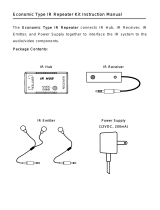
PLASMA PROOF IR REPEATER KIT
IR-KIT
For Receiving and Routing
Infrared Commands from Any
Remote Control to Concealed
Audio/Video Equipment
INSTALLATION & USER GUIDE

IR-KIT
PLASMA PROOF IR REPEATER KIT
TABLE OF CONTENTS
Features............................................................................................................................1
Product Overview...........................................................................................................2
Package Contents ..........................................................................................................4
Preparing for Installation..............................................................................................4
Installation.......................................................................................................................5
Operation..........................................................................................................................8
Troubleshooting ..............................................................................................................9
Specifications...............................................................................................................11
Warranty.........................................................................................................................13

1
FEATURES
IR-CB2
n Provides two IR Receiver
inputs and five IR Emitter
outputs
n Selectable high/low emitter
outputs for use with IR-E1HO
high output emitter or single
and dual emitters
n LED power indicator
n 12V DC status input jack and
LED indicator
Installation friendly design:
n Snap and Lock Connector
secures wire in place without
the use of a screwdriver
n 3.5mm emitter output jacks
n Wings allow for either vertical
of horizontal mounting
n Includes in-line UL listed
regulated power supply
IR-SMR Surface Mount IR Receiver
n Plasma-proof design
n Rejects interference from flat
panel displays, CFL lighting or
indirect sunlight
n Works with practically all
remotes
n Extended receiving range
n Green talkback LED indicates
when A/V system is on
n Blue talkback LED confirms
reception of IR signals
Installation friendly design:
n 10' of connecting wire included
n Reliable adhesive backing
IR-E1 Infrared Emitter
n Infrared pass through housing
n Miniature size and shape
Installation friendly design:
n 10' of cable with 3.5mm plug
n Reliable adhesive backing
n Includes IR Blocking Cover

PRODUCT OVERVIEW
2
1
3
7
4
2
6
5
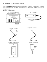
IR-CB2
IR-SMR
IR Blocking
Cover
Infrared
Transparent
Housing
10 feet of 2-conductor
24-gauge connecting wire
3.5mm mono
mini-plug
Self-adhesive tape
IR-E1
Infrared
LED

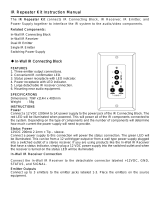
1. 12V DC Jack – Provides 12Volt DC power to
IR-CB2 via a regulated power supply.
2. IR Emitter Outputs – 3.5mm jacks provide output for
either single or dual low-level flashers.
3. 3-30V AC/DC Status – 3.5mm jack provides
system status to sensors/keypads via a 12V power
supply attached to a switched outlet on the system
receiver or a 12V trigger output.
4. 12V Output – When 12V DC is detected at the
status jack (#3) the 12V output jack will output
12V/200mA DC. This is useful for triggering external
devices and system automation.
5. Status/IR Confirmation LED – This LED performs
two functions: (1) it provides a visible indication of
system status via a green LED and (2) confirms the
reception of IR data via a blinking blue LED.
6. Emitter Hi/Low switch – Setting these switches to
the appropriate position allows you to connect
either a high-output flooding emitter (IR-E1HO)
or low-output emitter. There is one Hi/Low switch
for emitter port four and one Hi/Low switch for
emitter port five.
7. Sensor Inputs – Removable quick connect sensor
plug for connection of IR sensors to the system.
3

4
PACKAGE CONTENTS
n IR-CB2 x 1
n Snap and Lock Connectors x 2
n In-line power supply x 1
n Self-adhesive rubber feet x 4
n IR-SMR Receiver x 1
n Adhesive-backed strip for mounting x 1
n IR-E1 Emitters x 5
n IR Blocking Covers x 5
n Extra emitter adhesive strips x 10
PREPARING FOR INSTALLATION
The IR Receiver cables, emitter cables and the 12V
DC power supply cable must all reach the proposed
location of the IR-CB2 Connecting Block. Mark the
cables with wire labels, describing where the cables
originate from, rather than where they will terminate.
Locate a local un-switched AC outlet to be used to
power the IR-CB2 power supply.
Tools Required
n 1/8" Slotted screwdriver
n Wire labels
n Wire stripper

5
INSTALLATION
1. Select an appropriate location for the IR-CB2.
2. Run all the necessary wiring to the IR-CB2. Label
the wires for future reference.
3. Plug the supplied 12V DC power supply into the
un-switched AC outlet.
4. Plug the 12V DC power supply connector into the
IR-CB2 socket marked POWER.
5. After verifying that the AC outlet works, unplug the
power supply connector.
6. Determine the mounting location for the IR-SMR.
7. Make sure the mounting surface is clean.
8. Remove the protective coating from the self-
adhesive tape and attach the IR-SMR to the
mounting surface.
9. Run the IR-SMR cable. Label the cable for future
reference.
10. Locate the IR Connecting Block Snap and
Lock Connectors and remove them if they are
plugged in.
11. Use a small flathead screwdriver or your thumb to
raise the locking
tabs, exposing the
holes on the
connectors.
12. Insert each wire into
the appropriate hole
and snap down the locking tabs.
Figure 1
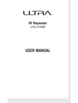
13. Insert the smooth side of the connector plug into
the smooth side of the IR Connecting Block socket.
14. Connect the IR-E1 Emitters to the emitter outputs.
15. Plug the 12V DC power supply connector into the
IR-CB2 socket marked POWER.
See installation diagram (page 6).
(White)
(Yellow) (Black)
(Red)
Figure 1

JobSite
IR-E1
Emitters
IR-SMR
Receiver
Home
Theater
Plasma Display
12V DC Power
Supply
(Not Supplied)
plugged into the
Switched Outlet
Home Theater
Receiver
Satellite Receiver
Cable TV Receiver
DVD Player
CD/Audio Player
Zone 2
In-Wall
Speaker
Optional
IR-FMR Receiver
IR-CB2
INSTALLATION DIAGRAM
6

7
Power Status
You can send a Power Status signal to IR-SMR
receiver by connecting a 12V DC power supply from
the switched AC power outlet of the preamp/receiver
to the status input jack of your IR-CB2. Any 12V DC
power supply with a minimum of 100mA current
capacity can be used.
Hi/Low Emitter Output Switches
Emitter Output positions 4 and 5 have Hi/Low output
options. Set these switches to the appropriate
position depending on what
JobSite Emitter you intend to
use. When you are using an
IR-E1 or IR- E2 Emitter, set the
switch in the LOW position. If
you are using a JobSite
IR-E1HO Emitter, set the
switch in the HI position.
Note: Using an IR-E1 or IR-E2 Emitter with the
Emitter Output Switch set to the HI position, can
damage the emitter.
12-Volt Trigger Output
The JobSite IR-CB2 provides a 12V
DC output that can be triggered
one of two ways:
1. The presence of status voltage
on the 12V DC status input jack.
2. Discrete infrared On and Off
commands.
This output can be used to trigger any device that
requires 12V DC to be activated.
Note: Status voltage takes priority over IR command.
Figure 2
3-30V
AC/DC
STATUS
IN
Figure 3

8
OPERATION
Test your IR Repeater system by following three
principal guidelines:
1. All components can be operated: Test all of your
remote controls for all of your equipment.
2. Operation is consistent: A good test is to
repeatedly step from Pause to Play with your VCR,
CD, DVD, or Tape player remote control. Operation
should be identical to standing in front of the
component with the remote control pointed
directly at the receiver window.
3. Maximum range between the remote control and
the JobSite IR Receiver is similar to the maximum
range between the remote control and the A/V
component’s IR Receiver: Typically a remote
control with two batteries will have a 15 to 20 foot
range and a remote with four batteries will have a
20 to 30 foot range.
Additional IR Receivers
The IR-Kit includes one surface mount receiver. The
included IR-CB2 Connecting Block will accommodate
a second IR Receiver. JobSite makes a variety of
receivers for virtually any application. See your
JobSite dealer for more information.

9
TROUBLESHOOTING
Bad Connections or Wiring
If the connections or wiring are wrong, loose,
shorted or open, the system will not operate properly.
The symptoms could include: Power LED flickers or
is off, IR Test LED is continuously flickering or on
without any remote control use, intermittent
operation or no operation.
Solution: Systematically troubleshoot
the wiring by:
1. Testing your power supply connections.
2. Testing your receiver connections.
3. Testing your emitter connections.
4. Testing your cable for shorts and opens.
IR Saturation
Sometimes the emitter output can saturate the IR
receiving window of a component. When this
occurs, the IR command will not be executed. This
can occur on an intermittent basis when there is a
Plasma TV in the system.
Solution:
1. Remove the IR Blocking Cover if you are using one.
2. Turn on the Plasma TV, because this may be
contributing to the problem.
3. Relocate the IR Emitter approximately 1/2" away
from the IR Receiving window.
4. Some experimentation will be required to
determine the best location for emitter.
Note: Do not use an IR Blocking Cover if a
component is sensitive to IR saturation.

10
Optical or Electromagnetic
Interference
Direct sunlight, reflections, neon signs and other
sources of infrared light or television sets, light
dimming controls and other sources of
electromagnetic fields can induce noise and
interference into your IR repeater system. Symptoms
can include: flashback LEDs continuously flickering
or on without any remote control use, poor range,
intermittent operation or no operation.
Solution: To eliminate EMI try the
following methods
1. Move the receiver or the receiver cable away from
the EMI source or move the source of the EMI
away from the receiver or the cable.
2. Connect the receiver’s GND terminal to true earth
ground (if this isn’t feasible use the main system
unit’s GND terminal).
Optical Feedback Loop
If you have an IR Receiver in the same room as a
emitter, and you have some low-level noise or
interference, an optical feedback loop can occur
which will interfere with proper operation. Symptoms
can include: poor range, intermittent operation or no
operation.
Solution: Replace IR-E1HO Emitters
You can eliminate optical feedback by replacing any
IR-E1HO “flooding Emitters” with IR-E1 or
IR-E2 Emitters and covering all emitters with the
supplied IR Blocking Covers.

11
SPECIFICATIONS
IR-CB2
IR system:
Works with practically all brands of IR remote
controls
Connections:
2 receiver inputs, 5 emitter outputs
Wiring requirements:
Category 5 or better
Home runs required from each IR receiver
Mounting:
Wall or flat surface: use drywall screws
Dimensions:
5-11/16" wide x 1-1/4" high x 2" deep
Power requirements:
110V to 12V DC power supply (included)
Warranty: 2 year limited
IR-SMR
IR system:
Works with practically all brands of IR remote
controls
IR receiving (varies by brand of remote control):
18'-30' range
From 20', 30 degrees off-axis
Wiring requirements:
Category 5 or better, home runs required
Mounting:
Self-adhesive, surface mount
Dimensions:
2" long x 1/2" wide x 1/4" high
Warranty: 2 year limited

12
SPECIFICATIONS (CONTINUED)
IR-E1
IR system:
Works with practically all brands of IR remote
controls
IR transmitting:
4' (line of sight)
Emitters mount directly to the IR window of a
component
Wiring requirements:
10' of 2-conductor 24-gauge wire with a 3.5mm plug
is supplied
Use 18-gauge for distances up to 20' and 16-gauge
for up to 200'
Mounting:
Self-adhesive, surface mount
Dimensions:
5/16" wide x 3/16" high x 1/2" deep
IR Blocking Cover Dimensions
2" wide x 2" high x 1/4" deep
Warranty: 2 year limited

13
LIMITED WARRANTY
JobSite Systems (“JOBSITE”), a Niles Audio Corporation
company, warrants its passive products (those not requiring
AC or battery power) to the original purchaser to be free of
manufacturing defects in material and workmanship for a
period of ten years from date of purchase.
JOBSITE warrants its passive loudspeaker products (those
not requiring AC or battery power) to the original purchaser
to be free of manufacturing defects in material and
workmanship for a period of five years from date of
purchase.
JOBSITE warrants its indoor/outdoor loudspeaker products
to the original purchaser to be free of manufacturing
defects in material and workmanship for a period of two
years from date of purchase.
JOBSITE warrants its all weather rock loudspeaker
products to the original purchaser to be free of
manufacturing defects in material and workmanship for a
period of five years from date of purchase.
JOBSITE warrants its active products (those requiring AC
or battery power) to the original purchaser to be free of
manufacturing defects in material and workmanship for a
period of two years from date of purchase.
This Warranty is subject to the following additional
conditions and limitations. The Warranty is void and
inapplicable if JOBSITE deems that the product has been
used or handled other than in accordance with the
instructions provided by the manufacturer, including, but not
limited to, damage caused by accident, mishandling,
improper installation, abuse, negligence, or normal wear
and tear, or any defect caused by repair to the product
other than by JOBSITE or an authorized JOBSITE wholesale
distributor.
To obtain warranty service, you must write to JOBSITE:
Include your name, address, telephone number, model
number and serial number of your unit, and a brief
description of the problem.
A factory Return Authorization Number will be sent to you.
DO NOT RETURN ANY UNIT WITHOUT FIRST RECEIVING
WRITTEN AUTHORIZATION AND SHIPPING
INSTRUCTIONS FROM JOBSITE.

14
If the above conditions are met, the purchaser’s sole
remedy shall be to return the product to JOBSITE, in which
case JOBSITE will repair or replace, at its sole option, the
defective product without charge for parts or labor.
JOBSITE will return the unit repaired or replaced under
warranty by shipping it by its usual shipping method from
the factory (only) at its expense within the United States of
America. THERE ARE NO OTHER WARRANTIES,
INCLUDING, WITHOUT LIMITATION, EITHER EXPRESS OR
IMPLIED WARRANTIES OF MERCHANTABILITY OR
FITNESS FOR A PARTICULAR PURPOSE, WITH RESPECT TO
THE PRODUCT.
REPAIR OR REPLACEMENT AS PROVIDED UNDER THIS
WARRANTY IS THE EXCLUSIVE REMEDY OF THE
CONSUMER/PURCHASER. NILES SHALL NOT BE
RESPONSIBLE FOR ANY INCIDENTAL OR CONSEQUENTIAL
DAMAGES EXCEPT TO THE EXTENT PROVIDED (OR
PROHIBITED) BY APPLICABLE LAW.
Some states do not allow the exclusion or limitation of
incidental or consequential damages, so the above
limitation may not apply to you. This warranty gives you
specific legal rights, and you may also have other rights,
which vary from state to state.
For the name of the nearest authorized JOBSITE wholesale
distributor, contact:
JobSite Systems
12331 S.W. 130 Street, Miami, Florida 33186
WWW.JOBSITESYSTEMS.COM

15
NOTES:

16
NOTES:

17

JOBSITE SYSTEMS
12331 S.W. 130 STREET, MIAMI, FLORIDA 33186
P 866.4JB.SITE (866.452.7483) – F 305.238.0185
WWW.JOBSITESYSTEMS.COM
© 2005 JobSite Systems. All rights reserved. JobSite, Pure Custom and Niles are registered trademarks of Niles Audio Corporation and the JobSite Logo
is a trademark of Niles Audio Corporation. All other trademarks are the property of their respective owners. Some JobSite products (or components
thereof) are manufactured under one or more U.S. Patents, foreign equivalents and/or pending patents (see product for details). Because we constantly
strive to improve our products, JobSite reserves the right to change product specifications, descriptions, and prices without notice. The technical and
other specifications of information contained herein are not intended to set forth all technical and other specifications of JobSite products. Additional
information can be obtained at WWW.JOBSITESYSTEMS.COM or by calling JobSite at 866.452.7483. Printed in China. 1/05 DS00428ACN
/