Zebra 49579LBr1.book Owner's manual
- Category
- Label printers
- Type
- Owner's manual
This manual is also suitable for

Zebra
170PAX3
™
-Series
User’s Guide

Proprietary Statement
This manual contains proprietary information of Zebra Technologies Corporation. It is intended solely for the
information and use of parties operating and maintaining the equipment described herein. Such proprietary infor-
mation may not be used, reproduced, or disclosed to third parties for any other purpose without the expressed writ-
ten permission of Zebra Technologies Corporation.
Product Improvements
Continuous improvement of products is a policy of Zebra Technologies Corporation. All specifications and signs
are subject to change without notice.
FCC Compliance Statement
This equipment has been tested and found to comply with the limits for a Class A digital Device, pursuant to Part
15 of the FCC Rules. These limits are designed to provide reasonable protection against harmful interference when
the equipment is operated in a commercial environment. This equipment generates, uses and can radiate radio fre-
quency energy and, if not installed and used in accordance with the instructions manual, may cause harmful inter-
ference to radio communications. Operation of this equipment in a residential area is likely to cause harmful
interference in which case the user will be required to correct the interference at his own expense.
In order to insure compliance, this print engine must be used with a Shielded Power Cord and Shielded Communi-
cation Cables.
“The user is cautioned that any changes or modifications not expressly approved by Zebra Technologies Corpora-
tion could void the user’s authority to operate the equipment.”
Canadian DOC Compliance Statement
This digital apparatus does not exceed the Class A limits for radio noise emissions from digital apparatus as set out
in the radio interference regulations of the Canadian Department of Communications.
Liability Disclaimer
Zebra Technologies Corporation takes steps to assure that its published Engineering Specifications and Manuals
are correct; however, errors do occur. Zebra Technologies Corporation reserves the right to correct any such errors
and disclaims liability resulting therefrom.
No Liability for Consequential Damage
In no event shall Zebra Technologies Corporation or anyone else involved in the creation, production, or delivery
of the accompanying product (including hardware and software) be liable for any damages whatsoever (including,
without limitation, damages for loss of business profits, business interruption, loss of business information, or other
pecuniary loss) arising out of the use of or the results of use of or inability to use such product, even if Zebra Tech-
nologies Corporation has been advised of the possibility of such damages. Because some states do not allow the
exclusion or limitation of liability for consequential or incidental damages, the above limitation may not apply to
you.
Copyrights
The copyrights in this manual and the label print engine described therein are owned by Zebra Technologies Cor-
poration. All rights are reserved. Unauthorized reproduction of this manual or the software in the label print engine
may result in imprisonment of up to one year and fines of up to $10,000 (17 U.S.C.506). Copyright violators may
be subject to civil liability.
Zebra 170PA X ™, 172PA X ™, 173PA X ™, ZebraNet™, ProPlus™, Platinum™, and Z-Tools™ are trademarks and
ZPL
®
, ZPL II
®
, and BAR-ONE
®
are registered trademarks of Zebra Technologies Corporation.
Centronics
®
is a registered trademark of Genicom Corporation.
IBM
®
is a registered trademark of IBM Corporation.
© 2000 Zebra Technologies Corporation. All rights reserved.

1
Table of Contents
Introduction ............................................................................................... 5
Zebra 170PAX3 Print Engine .......................................................................................5
Getting Started ..............................................................................................................5
Print Engine Mounting..................................................................................................5
Communications ...........................................................................................................6
Print Engine Power .......................................................................................................6
Media & Ribbon Loading......................................................................... 9
Ribbon Loading ..........................................................................................................11
Right Hand Units ........................................................................................................11
Left Hand Units ..........................................................................................................12
Removing Used Ribbon..............................................................................................13
Media Sensor Position............................................................................. 15
Reflective Media Sensor.............................................................................................15
Transmissive Media Sensor ........................................................................................15
Print Engine Operation .......................................................................... 17
Power On/Off Switch..................................................................................................17
Control Panel Keys .....................................................................................................17
Liquid Crystal Display................................................................................................18
Control Panel Indicator LEDs.....................................................................................19
Configuration & Calibration.................................................................. 21
Entering the Setup Mode ............................................................................................21
Changing Password-Protected Parameter ..................................................................21
Leaving the Setup Mode .............................................................................................22
Configuration and Calibration Sequence....................................................................23
Media and Ribbon Sensor Calibration........................................................................27
Media and Ribbon Calibration Procedure ..................................................................28
Setting Communication Parameters............................................................................29
Selecting Prefix and Delimiter Characters..................................................................31
Selecting ZPL Mode ...................................................................................................32
Power-Up and Head Close Parameters.......................................................................33
Label Positioning Parameters .....................................................................................34
Printing Controls.........................................................................................................36
Sensor Values .............................................................................................................38
Care & Adjustments ............................................................................... 43
Cleaning ......................................................................................................................43
Toggle Positioning......................................................................................................46
Printhead Pressure Adjustment...................................................................................46

2
Troubleshooting .......................................................................................49
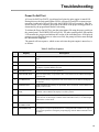
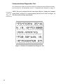
Power On Self Test .....................................................................................................49
Power On Troubleshooting.........................................................................................50
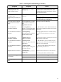
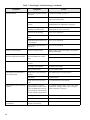
Print Engine Troubleshooting.....................................................................................50
Print Engine Self Tests ...............................................................................................54
CANCEL Key Self Test .............................................................................................55
PAUSE Key Self Test.................................................................................................56
FEED Key Self Test ...................................................................................................57
FEED Key and PAUSE Key.......................................................................................58
Communications Diagnostics Test .............................................................................59
Options......................................................................................................61
Single In-line Memory Module (SIMM) ....................................................................61
Personal Computer Memory Card Interface Association
(PCMCIA) Memory Card...........................................................................................61
Communication Interfaces..........................................................................................61
ZebraNet™ PrintServer II...........................................................................................61
Print Engine Specifications.....................................................................63
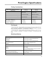
Printing Considerations...............................................................................................63
Print Speeds ................................................................................................................63
Media Specifications...................................................................................................63
Ribbon Specifications .................................................................................................64
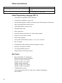
Zebra Programming Language (ZPL II) .....................................................................64
Bar Codes....................................................................................................................64
Communication Specifications ...................................................................................65
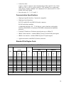
Standard Print Engine Fonts .......................................................................................65
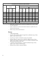
Memory.......................................................................................................................66
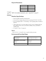
Physical Dimensions...................................................................................................67
Electrical Specifications .............................................................................................67
Fuses ...........................................................................................................................67
Environmental Operating Range ................................................................................67
Appendix A...............................................................................................69
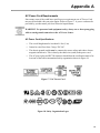
AC Power Cord Requirements ...................................................................................69
Power Fuse Replacement............................................................................................70
Shipping ......................................................................................................................71
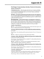
Appendix B...............................................................................................73
Print Engine Communications Interface Technical Information................................73
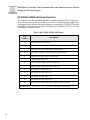
RS-232/RS-422/RS-485 Serial Data Port ...................................................................74
Centronics-Compatible Parallel Data Port..................................................................77
Cabling Requirements.................................................................................................78
Applicator Interface Connector...................................................................................78
Appendix C...............................................................................................81
ASCII Code Chart.......................................................................................................81

3
Appendix D .............................................................................................. 83
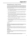
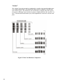
Adjusting Darkness For “In-Spec” Bar Codes ...........................................................83
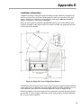
Appendix E............................................................................................... 85
Installation Information ..............................................................................................85
Glossary.................................................................................................... 89

4

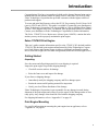
5
Introduction
Congratulations! You have just purchased a high-quality thermal demand print engine
manufactured by the industry leader in quality, service, and value. For over 30 years,
Zebra Technologies Corporation has provided customers with the highest caliber of
products and support.
To create and print label formats, refer to the ZPL II Programming Guide Volume I & II
(part #s 45541L and 45542L). This guide is available by contacting your distributor or
Zebra Technologies Corporation. It is also available as a file to download from Zebra’s
web site “www.support.zebra.com”. In addition, label preparation software is available.
Contact your distributor or Zebra Technologies Corporation for further information.
The Zebra 170PAX™-Series Maintenance Manual (part # 49803L) contains the infor-
mation you may need to properly maintain the print engine.
Zebra 170PAX3 Print Engine
This user’s guide contains information specific to the 172PAX3 (203 dot/inch) and the
173PAX3 (300 dot/inch) print engines manufactured by Zebra Technologies Corpora-
tion. Each of these print engines comes in either a right hand configuration (media
moves from left to right) or a left hand configuration (media moves from right to left.)
Getting Started
Unpacking
Save the carton and all packing materials in case shipping is required.
Inspect the print engine for possible shipping damage:
• Check all exterior surfaces for damage.
• Raise the front cover and inspect for damage
If you discover shipping damage:
• Immediately notify the shipping company and file a damage report.
• Retain the carton and all packing material for inspection.
• Notify your local Zebra distributor of the damage.
Zebra Technologies Corporation is not responsible for any damage incurred during
shipment of the print engine and will not cover the repair of this damage under its war-
ranty policy. Any damage claim should be filed with the shipping company.
For shipping information, refer to “Appendix A” on page 69.
Print Engine Mounting
For specific information on mounting the print engine into an applicator, refer to
“Appendix E” on page 85.

6
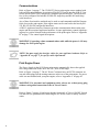
Communications
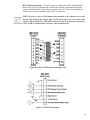
Refer to Figure 1 on page 7. The 170PAX3™-Series print engine comes standard with
both an Electronics Industries Association (EIA) RS-232 serial interface (DB-25 Con-
nector) and an IEEE 1284 Centronics®-compatible parallel interface. The serial inter-
face is also configured for both RS-422/RS-485 single drop and RS-485 multi-drop
serial interfaces.
Any of these four interface methods may be used to send commands and label formats
from a host to the print engine. Print engine status can be sent back to the host by RS-
232, RS-422, RS-485 and parallel interfaces.
A DB-15 Applicator Interface Connector provides communication between the print
engine and the associated applicator hardware. In some applications, control signal tim-
ing may be a critical element in the performance of the print engine. Refer to “Appendix
B” on page 73 for control signal descriptions.
WARNING! Connecting a data communications cable while the power is ON may
damage the PAX3 print engine.
NOTE: You must supply the interface cables for your applicator hardware. Refer to
“Appendix B” on page 73 for specific cable requirements.
Print Engine Power
The Power Supply in the PAX3-Series print engine automatically detects the applied
line voltage and works in the 90 to 264 VAC, 48 to 62 Hz range.
Refer to Figure 1 on page 7. The AC Power Cord must have an IEC230 connector on
one end which plugs into the mating connector at the rear of the print engine. If a power
cable was not included with your print engine, refer to “Appendix A” on page 69.
WARNING! For personnel and equipment safety, always use a three-prong plug
with an earth ground connection to the AC Power Source.
Refer to Figure 7 on page 18 and insure that the front panel AC Power ON/OFF Switch
is in the OFF (O) position before connecting the AC Power cord to a nearby electrical
outlet.

7
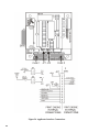
Figure 1. Cable Connections
PARALLEL
INTERFACE
CONNECTOR
DB-25 SERIAL
INTERFACE
CONNECTOR
DB-15 APPLICATOR
INTERFACE
CONNECTOR
AC POWER
CONNECTOR
LEFT HAND PAX PRINT ENGINE
RIGHT HAND PAX PRINT ENGINE
PARALLEL
INTERFACE
CONNECTOR
DB-25 SERIAL
INTERFACE
CONNECTOR
AC POWER
CONNECTOR
DB-15 APPLICATOR
INTERFACE
CONNECTOR

8

9
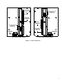
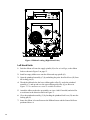
Media & Ribbon Loading
If you have a right hand print engine (printed labels are presented on the right hand side
of the unit), refer to Figure 2 while performing the procedure shown below. If you have
a left hand unit (printed labels are presented on the left hand side of the unit), refer to
Figure 3 on page 10.
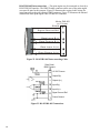
1. Load the media on the media supply reel of the applicator (refer to the applicator’s
user’s manual).
2. Grasp the thumb nut (A) and slide the outer media edge guide (B) as far out from
the print engine frame as possible. (The thumb nut does not have to be loosened.)
3. Open the printhead assembly (C) by unlatching the printhead lock lever (D) from
the locking pin (E).
4. Raise the pinch roller (F) by pressing down on the pinch roller assembly latch (G).
Thread the media under the upper guide post (H), between the pinch roller and the
associated rubber pinch roller, and under the printhead assembly (C) until approxi-
mately 30" (75 cm) of media extends out of the print engine.
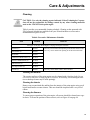
Figure 2. Media Loading (Right-Hand Units)
OPEN
E
G
H
C
D
MEDIA
PATH
MEDIA
BACKING
LABEL
SEE DETAIL
IB
A
F
M
OPEN
DETAIL
K
L
J

10
5. Ensure the media is aligned within the print path then close the printhead assembly
(C) by rotating the printhead lock lever (D) until it latches onto the locking pin (E).
6. Secure the pinch roller (F) in position by pressing down on the top of the pinch
roller latch (G) until the assembly snaps closed.
7. Position the outer media edge guide (B) so it just touches the outer edge of the
media.
8. Raise the peel roller latch (I) and the peel roller assembly (J) will pivot down to a
vertical position.
9. Thread the backing material around the peel bar (K), under the platen roller (L), and
through the peel roller assembly (J). (See DETAIL.)
NOTE: If the applicator has an air tube, route the media between the air tube and the
peel bar. Do not thread the media over this tube!
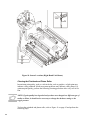
Figure 3. Media Loading (Left-Hand Units)
OPEN
E
G
H
C
D
MEDIA
PATH
MEDIA
BACKING
LABEL
SEE DETAIL
I
B
A
F
M
OPEN
DETAIL
K
L
J

11
10. Rotate the peel roller assembly (J) up until it latches closed.
11. Thread the backing material under the lower guide post (M) and around the take-up
spindle of the applicator (refer to the applicator’s user’s manual).
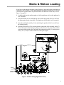
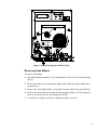
Ribbon Loading
To load ribbon, refer to Figure 4 on page 12 (for right-hand units) or Figure 5 on
page 13 (for left-hand units).
NOTE: Do not load ribbon if the print engine is to be used in the direct thermal
mode.
CAUTION: When installing the ribbon roll on the ribbon supply spindle, make
sure to push the ribbon roll against the stop with the ribbon aligned squarely with
its core. Do not use ribbon narrower than the media. If the printhead is not pro-
tected by the smooth backing of the ribbon, premature printhead failure may
result due to excessive abrasion.
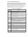
Right Hand Units
1. Push the ribbon roll onto the supply spindle (N) as far as it will go, so the ribbon
feeds as shown in Figure 4 on page 12.
2. Install an empty ribbon core onto the ribbon take-up spindle (O).
3. Open the printhead assembly (C) by unlatching the print- head lock lever (D) from
the locking pin (E).
4. Thread the ribbon below the lower ribbon guide roller (P), under the printhead
assembly (C), and up and over the upper ribbon guide roller (Q) as shown in Figure
4. Use caution not to crease or wrinkle the ribbon!
5. Attach the ribbon to the take-up spindle core (use a label if needed) and wind for
several turns in the direction shown in Figure 4.
6. Close the printhead assembly (C) by latching the printhead lock lever (D) onto the
locking pin (E).
7. Insure the ribbon is located between the Ribbon Sensor and the Sensor Reflector
positioned above it.

12
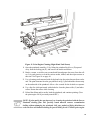
Figure 4. Ribbon Loading (Right-Hand Units)
Left Hand Units
1. Push the ribbon roll onto the supply spindle (N) as far as it will go, so the ribbon
feeds as shown in Figure 5 on page 13.
2. Install an empty ribbon core onto the ribbon take-up spindle (O).
3. Open the printhead assembly (C) by unlatching the print- head lock lever (D) from
the locking pin (E).
4. Thread the ribbon below the lower ribbon guide roller (P), under the printhead
assembly (C), and up and over the upper ribbon guide roller (Q) as shown in
Figure 5. Use caution not to crease or wrinkle the ribbon!
5. Attach the ribbon to the take-up spindle core (use a label if needed) and wind for
several turns in the direction shown in Figure 5.
6. Close the printhead assembly (C) by latching the printhead lock lever (D) onto the
locking pin (E).
7. Insure the ribbon is located between the Ribbon Sensor and the Sensor Reflector
positioned above it.
OPEN
CALIBRA TE
PREVIOUS
NEXT
SETUP /EXIT
PAU S E
CANCEL
FEED
DATA POWERERRORRIBBONMEDI APAU SE
O
N
E
P
C
D
Q

13
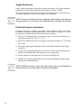
Figure 5. Ribbon Loading (Left-Hand Units)
Removing Used Ribbon
To remove used ribbon:
1. Open the printhead assembly (C) by unlatching the lock lever (D) from the locking
pin (E).
2. Remove the ribbon between the upper ribbon guide roller (Q) and the ribbon take-
up spindle (O).
3. Remove the used ribbon and the core together from the ribbon take-up spindle (O).
4. Remove the empty ribbon core from the ribbon supply spindle (N). This empty rib-
bon core can be saved to use for loading new ribbon.
5. To load the new ribbon, refer to the “Ribbon Loading” on page 11.
OPEN
CALIBRATE
PREVIOUS
NEXT
SETUP/EXIT
PAU SE
CANCEL
FEED
DATA POWERERRORRIBB ONMEDIAPA U S E
O
N
E
P
C
Q
D

14

15
Media Sensor Position
Reflective Media Sensor
Some types of media have black marks printed on the underside of the backing material
that act as “Start of Label” indicators. These black marks are sensed by the reflective
media sensor mounted to the lead screaw. The position of this sensor is not adjustable.
If you are using this type of media, refer to the “Print Engine Specifications” on page 63
of this guide for information about black mark requirements.
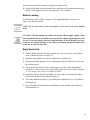
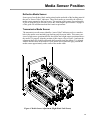
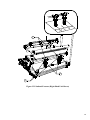
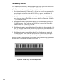
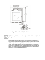
Transmissive Media Sensor
The transmissive media sensor identifies “start of label” indicators such as a notch or
hole in the media or an interlabel gap (backing only) between labels. This sensor con-
sists of a light source (positioned below the media) and a light sensor (positioned above
the media). To properly align the position of this sensor, refer to Figure 6 and turn the
adjustment knob (S) on the media guide shelf assembly until the sensor (T) is aligned
with the notch or hole in the media. If your media uses an interlabel gap, position the
media sensor approximately at the center of the media width.
Figure 6. Media Sensor Adjustment (Right-Hand Unit Shown)
T
S

16

17
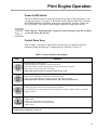
Print Engine Operation
Power On/Off Switch
The Power On/Off Switch is located just to the left (or right) of the print engine’s con-
trol panel (see Figure 7 on page 18). When this switch is placed in the ON (1) position,
the POWER light goes ON and the print engine automatically performs a Power On
Self Test (POST). The Liquid Crystal Display validates the steps in the self test.
NOTE: Refer to “Troubleshooting” on page 49 if the print engine stops due to failing
a test in the Power On Self Test.
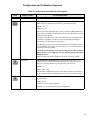
Control Panel Keys
Refer to Figure 7 on page 18. Specific uses of these keys are explained with each
parameter setting description in “Configuration & Calibration” on page 21.
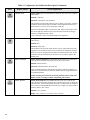
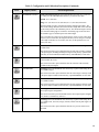
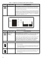
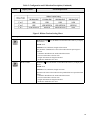
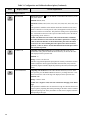
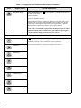
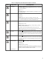
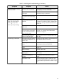
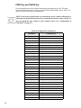
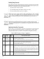
Table 1: Control Panel Key Description
Key Function
Starts and stops the printing process.
• If the print engine is not printing: no printing can occur.
• If the print engine is printing: printing stops once the current label is complete.
Press to remove error messages from the display.
NOTE: Pause mode can also be activated via ZPL II (~PP, ^PP).
Forces the print engine to feed one blank label each time the key is pressed.
• Print engine not printing: one blank label immediately feeds.
• Printing: one blank label feeds after the current batch of labels is complete.
NOTE: Equivalent to the Slew to Home Position (~PH, ^PH) ZPL II instruction.
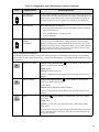
When in the pause mode, this key will cancel print jobs.
• Print job in queue: press once for each print job to be deleted.
• Press and hold for several seconds to cancel all print jobs in the print engine’s memory. The DATA
light will turn off.
When in Pause mode, this key will calibrate the print engine for:
• Media length.
• Media type (continuous or non-continuous).
• Print mode (direct thermal or thermal transfer).
• Sensor values.
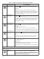
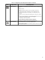
NOTE: The keys below are used only when configuring the print engine. Specific uses of these keys are explained in
“Configuration & Calibration” on page 21.

18
.
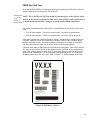
Figure 7. Control Panel (Right-Hand Unit)
Liquid Crystal Display
The control panel shown in Figure 7 contains a backlit Liquid Crystal Display (LCD).
It shows operational status as well as programming modes and feature parameters.
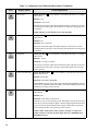
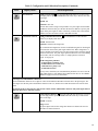
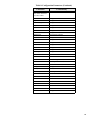
• Scrolls back to the previous parameter.
• Press and hold to quickly go backward through parameter sets.
• Scrolls forward to the next parameter. (Saves any changes you’ve made in the
configuration and calibration sequence.)
• Press and hold to quickly advance through parameter sets.
Enters and exits the configuration mode.
These keys change the parameter values. They are used in different ways depending on the parameter
displayed. Common uses are: to increase/decrease a value, answer “yes” or “no,” indicate “on” or “off,”
scroll through several choices, input the password, or set up the print engine for a firmware download.
Table 1: Control Panel Key Description (Continued)
Key Function
Page is loading ...
Page is loading ...
Page is loading ...
Page is loading ...
Page is loading ...
Page is loading ...
Page is loading ...
Page is loading ...
Page is loading ...
Page is loading ...
Page is loading ...
Page is loading ...
Page is loading ...
Page is loading ...
Page is loading ...
Page is loading ...
Page is loading ...
Page is loading ...
Page is loading ...
Page is loading ...
Page is loading ...
Page is loading ...
Page is loading ...
Page is loading ...
Page is loading ...
Page is loading ...
Page is loading ...
Page is loading ...
Page is loading ...
Page is loading ...
Page is loading ...
Page is loading ...
Page is loading ...
Page is loading ...
Page is loading ...
Page is loading ...
Page is loading ...
Page is loading ...
Page is loading ...
Page is loading ...
Page is loading ...
Page is loading ...
Page is loading ...
Page is loading ...
Page is loading ...
Page is loading ...
Page is loading ...
Page is loading ...
Page is loading ...
Page is loading ...
Page is loading ...
Page is loading ...
Page is loading ...
Page is loading ...
Page is loading ...
Page is loading ...
Page is loading ...
Page is loading ...
Page is loading ...
Page is loading ...
Page is loading ...
Page is loading ...
Page is loading ...
Page is loading ...
Page is loading ...
Page is loading ...
Page is loading ...
Page is loading ...
Page is loading ...
Page is loading ...
Page is loading ...
Page is loading ...
Page is loading ...
Page is loading ...
Page is loading ...
Page is loading ...
Page is loading ...
Page is loading ...
Page is loading ...
Page is loading ...
-
 1
1
-
 2
2
-
 3
3
-
 4
4
-
 5
5
-
 6
6
-
 7
7
-
 8
8
-
 9
9
-
 10
10
-
 11
11
-
 12
12
-
 13
13
-
 14
14
-
 15
15
-
 16
16
-
 17
17
-
 18
18
-
 19
19
-
 20
20
-
 21
21
-
 22
22
-
 23
23
-
 24
24
-
 25
25
-
 26
26
-
 27
27
-
 28
28
-
 29
29
-
 30
30
-
 31
31
-
 32
32
-
 33
33
-
 34
34
-
 35
35
-
 36
36
-
 37
37
-
 38
38
-
 39
39
-
 40
40
-
 41
41
-
 42
42
-
 43
43
-
 44
44
-
 45
45
-
 46
46
-
 47
47
-
 48
48
-
 49
49
-
 50
50
-
 51
51
-
 52
52
-
 53
53
-
 54
54
-
 55
55
-
 56
56
-
 57
57
-
 58
58
-
 59
59
-
 60
60
-
 61
61
-
 62
62
-
 63
63
-
 64
64
-
 65
65
-
 66
66
-
 67
67
-
 68
68
-
 69
69
-
 70
70
-
 71
71
-
 72
72
-
 73
73
-
 74
74
-
 75
75
-
 76
76
-
 77
77
-
 78
78
-
 79
79
-
 80
80
-
 81
81
-
 82
82
-
 83
83
-
 84
84
-
 85
85
-
 86
86
-
 87
87
-
 88
88
-
 89
89
-
 90
90
-
 91
91
-
 92
92
-
 93
93
-
 94
94
-
 95
95
-
 96
96
-
 97
97
-
 98
98
-
 99
99
-
 100
100


Zebra 49579LBr1.book Owner's manual
- Category
- Label printers
- Type
- Owner's manual
- This manual is also suitable for
Ask a question and I''ll find the answer in the document
Finding information in a document is now easier with AI
Related papers

Other documents
-
 Zebra Technologies 170PAX2TM User manual
-
 Zebra Technologies R170XI User manual
-
 Genicom 90 TM User manual
-
Brady Bradyprinter THT 300X-PLUS User manual
-
 Zebra Technologies 3ULQWHUV User manual
-
-
-
SATO TXPSX5 User manual
-
 T'nB NEEC010 Datasheet
-


