Page is loading ...

INSTALLATION INSTRUCTIONS
CHIEF MANUFACTURING INC.
1-800-582-6480 952-894-6280 FAX 952-894-6918
8401 EAGLE CREEK PARKWAY, STE 700
SAVAGE, MINNESOTA 55378 USA
8800-000058 Rev E
2007 Chief Manufacturing
www.chiefmfg.com
06/07
BEFORE YOU BEGIN
LARGE FLAT PANEL IN WALL ENCLOSURE
Model: PAC-500
Specifications:
• Designed for in-wall installation spanning a
minimum of 3 wood studs, 16" on center.
• Accomodates MWR, PWR and PNR swing arm
mounts.
• Cutouts provided for single gang electrical box
and grommet hole for audio/video cables.
• Weight capacity of 200 lbs (90 kg).
NOTE: Shown with PNR mount installed; MWR/PWR
mount similar (mount not included).
WARNING: It is the installer’s responsibility to make sure all components are properly assembled and installed
using the instructions provided. Failure to read, thoroughly understand, and follow all instructions can result in
serious personal injury, damage to equipment, or voiding of factory warranty.
• If you have any questions about this these instructions or your specific installation, contact Chief Manufacturing
at 1-800-582-6480 or 952-894-6280.

Model: PAC-500 Installation Instructions
2
IMPORTANT WARNINGS AND CAUTIONS!
WARNING: A WARNING alerts you to the possibility of serious injury or death if you do not follow the instructions.
CAUTION: A CAUTION alerts you to the possibility of damage or destruction of equipment if you do not follow the
corresponding instructions.
WARNING: It is the installer’s responsibility to make sure the structure to which this unit is attached can support five
times the combined weight of all equipment. Reinforce the structure as required before installing the unit. Failure to
provide adequate structural strength for this unit can result in serious personal injury or damage to equipment!
WARNING: It is the installer’s responsibility to make sure the combined weight of the display, accessories, and any
other attached equipment must not exceed 200 lbs (90 kg), the maximum support weight of this unit. Exceeding the
maximum support weight can result in serious personal injury or damage to equipment!
WARNING: Make sure the latch securing the display is fully closed at all times except when removing or installing
the display. The latch must be fully closed when installing or removing cables from the display.
WARNING: Watch for pinch points. Do not put your fingers between movable parts.
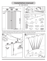
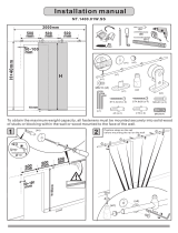
DIMENSIONS
30.00
2 x 19.500
2 x 5.500
12 x 2.000
2 x 2.375
2 x 2.375
DETAIL A
SCALE 1 : 2
2 X 2.125
DETAIL B
SCALE 1 : 2
3.855
1.875
4.000
12.000
12 x .390
20.000
27.000
19.000
7.000 2.000
A
B

Installation Instructions Model: PAC-500
3
TOOLS REQUIRED FOR INSTALLATION
• Stud Sensor
• Level
• Saw
• Tape Measure
• Screwdriver (for wood screws)
• 9/16" Wrench
• 3/16" Hex Key (provided)
• 4mm Hex Key (provided)
• 4mm Hex Bit (provided)
NOTE: Other tools may be required depending on your
method of installation.
PARTS
After unpacking carton, inspect and verify contents (See
Figure 1). If any listed parts are missing or damaged,
contact Chief Customer Service at 1-800-582-6480.
Figure 1: Parts
Table 1: Parts
Item Description Qty
10 HOUSING, In-Wall 1
20 BRACKET, Upper 1
30 BRACKET, Lower (MWR/PWR only) 1
40 BRACKET, Lower (PNR only) 1
50 MOULDING, Vertical 2
60 MOULDING, Horizontal 2
70 SCREW, Button Head Cap, 5/16"-18 x 3/4" 4
80 SCREW, Button Head Cap, 3/8"-16 x 5/8" 4
90 SCREW, Flat Head Cap, 3/8"-16 x 3/4" 2
100 BOLT, Connector, 7mm x 40mm 12
110 WASHER, Flat Machine Screw, 1/4" 4
120 WASHER, Lock, Split, 5/16" 4
130 WASHER, Lock, Split, 3/8" 4
140 PAD, Felt, 1/8" thick 2
150 TAPE, Foam, Square 18
160 COVER, White, 9/16" diameter 4
170 KEY, Hex, 3/16" (slightly larger than 180 below) 1
180 KEY, Hex, 4mm 1
190 BIT, Hex, 4mm 1
200 SHIM, Engineered Wood (package; not shown) 1
201 KEY, Hex, 7/32" 1
SUPPORT BLOCKS, wood 2x4, 8" long
(required, not supplied)
8
HORIZONTAL FRAMING, wood 2x4, 14-1/2"
long; exact length dependent upon specific
installation (required, not supplied)
4
SCREW, Wood, #10 x 2-1/2"
(required, not supplied)
40
ELECTRICAL BOX (optional, not supplied) 1
GROMMET (optional, not supplied) 1
10
20
30
40
60
50
90
100
110
201
140
150
160
170
180
190
70
80
120
200
130

Model: PAC-500 Installation Instructions
4
INSTALLATION AND ASSEMBLY
The following instructions are applicable to:
• Three 2x4 studs, 16" on center; other installations
are possible with increased framing complexity.
• MWR/PWR (single swing arm) and PNR (double
swing arm) mounts.
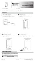
OPEN WALL
1. Determine approximate mounting location, keeping in
mind the display size.
! IMPORTANT: Installation of housing (10) in 2x4 wall
results in nearly direct contact with vertical studs and
opposite (back) wall. Inadequate space will remain for
electrical wires/cables, plumbing, ductwork, or insulation.
Locate housing (10) accordingly.
2. Use a stud sensor to locate applicable wood studs.
Mark locations with a pencil.
3. Center and level housing (10) between marked studs.
Using housing (10) as a template, draw pencil line
completely around housing (10) (See Figure 2).
NOTE: A 1/4" gap between sides of housing (10) and
adjacent studs is typical.
Figure 2: Open Wall
WARNING: ELECTRICAL SHOCK HAZARD! Cutting
or drilling into electrical wires and cables can cause
DEATH or SERIOUS PERSONAL INJURY! ALWAYS
make certain area behind mounting surfaces is free of
electrical wires and cables before cutting, drilling, or
installing mount fasteners.
WARNING: EXPLOSION AND FIRE HAZARD!
Cutting or drilling into gas plumbing can cause DEATH
or SERIOUS PERSONAL INJURY! ALWAYS make
certain area behind mounting surfaces is free of gas,
water, waste, or any other plumbing before cutting,
drilling, or installing mount fasteners.
4. Cut drywall on outside edge of line (to facilitate
installation of housing (10)) and remove.
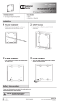
FRAME HOUSING
The exposed portion of the center wood stud must be
removed and the resulting cavity completely framed with
wood. The following steps are suggested; the actual
procedure is dependent upon the specific installation.
WARNING: STRUCTURAL FAILURE HAZARD!
Ensure removal of center stud will not cause
unacceptable loss of structural strength. Consult a
qualified building contractor and applicable building
codes. Failure to take adequate precautions can
cause DEATH or SERIOUS PERSONAL INJURY!
1. Remove exposed portion of center wood stud flush
with upper and lower drywall edges (See Figure 3).
NOTE: Stud may be attached to the opposite (back) wall.
Figure 3: Frame Housing
2. Cut 4 support blocks out of 2x4 wood, each
approximately 8" long.
3. Attach each support block to the corresponding stud
with three #10 x 2-1/2" countersunk wood screws.
Ensure that screws are far enough from end of block
to prevent interference with framing screws installed
in next step (See Figure 3).
NOTE: Use of wood screws (not included) instead of nails
is less likely to cause damage to surrounding
drywall or paint.
4. If necessary, cut rectangular hole in horizontal
framing to accomodate electrical box. Do NOT
eliminate bolts (100) to accomodate electrical
installation. All 12 bolts (100) must be used to secure
housing (10) to wall structure.
Wood Studs
Housing
1/4"
Horizontal
Framing
Support
Blocks
(4 places)
Top View
Wood
(5 places)
Screws
(Typical for each
support block)

Installation Instructions Model: PAC-500
5
5. Attach horizontal framing to each support block with
two #10 x 2-1/2" countersunk wood screws (See
Figure 3).
INSTALL HOUSING
WARNING: ELECTRICAL SHOCK AND FIRE
HAZARD! Consult a qualified electrical contractor and
applicable electrical codes. Failure to take adequate
precautions can cause DEATH or SERIOUS
PERSONAL INJURY!
1. If applicable:
• Attach electrical box to housing (10) and connect
electrical wiring.
NOTE: The cutout in housing is sized to accommodate a
standard RACO Single Gang junction box.
• Route audio/visual cables through grommet (not
supplied) into housing (10).
NOTE: Housing (10) can be rotated 180° to position
electrical and audio/visual cutouts.
2. Center housing (10) in framed cavity. Ensure housing
(10) protrudes 3/8" - 1/2" beyond front face of wood
stud (for 1/2" drywall; adjust as required for other wall
construction) (See Figure 4).
Figure 4: Install Housing
CAUTION: Housing (10) must either be in direct
contact with studs/horizontal framing, or shims must be
installed. Failure to do so will result in deformation of
housing (10) when bolts (100) are tightened.
3. Cut and overlap shims (200) as required to
completely fill space between fastener holes in
housing (10) and studs/horizontal framing
(See Figure 4).
4. Using key (180) or bit (190) install all 12 bolts (100)
through housing (10) (and shims (200), if required)
into studs/horizontal framing (See Figure 4). Tighten
securely.
TRANSFER MWR/PWR/PNR MOUNT ASSEMBLY
NOTE: See instructions that came with MWR/PWR/PNR
mount for specific display removal procedures.
1. Disconnect all cables from display.
NOTE: Cables can remain installed in mount arm
channel(s).
2. Remove PAC-140 Q-Clamp (if installed) and open
latching flag.
WARNING: Display is very heavy! Ensure display can
be safely lifted and maneuvered as required to remove
from mount. Failure to take adequate precautions can
result in serious personal injury or damage to
equipment!
3. Lift and maneuver display mounting buttons out of
button openings. Place display on protective surface.
4. Using 9/16" wrench, remove and discard four bolts
and washers attaching top and bottom brackets to
mount assembly (See Figure 5). Place mount
assembly on protective surface.
Figure 5: Remove Mount
5. Using key (170), attach upper bracket (20) to housing
(10) with screws (70), washers (120), and washers
(110) (See Figure 6). Do not tighten screws (70) at
this time.
NOTE: Bracket (20) is shown centered for PNR
installation. Bracket (20) is offset to the right for
MWR/PWR installation.
200
3/8" - 1/2"
(12 places,
as required)
100
(12 places)
Wood
Stud
NOTE: PNR mount faceplace removed for clarity;
MWR/PWR mount similar.
Attach Bolts

Model: PAC-500 Installation Instructions
6
Figure 6: Attach Upper Bracket
6. Attach lower bracket (30):
• MWR/PWR mount: Using key (170), attach lower
bracket (30) to mount assembly with screws (80)
and washers (130) (See Figure 7). Tighten
securely.
• PNR mount: Using key (170), attach lower
bracket (40) to mount assembly with screws (90)
(See Figure 8). Tighten securely, and then install
adhesive felt pad (140) to each screw head (90).
Figure 7: Attach Lower Bracket (MWR/PWR Mount)
Figure 8: Attach Lower Bracket (PNR Mount)
7. Tilt and insert upper portion of mount assembly into
upper bracket (20), then tilt and insert lower portion of
mount assembly into housing (10) (See Figure 9).
Figure 9: Insert Mount
8. To gain access to fastener holes for next steps, hold
lower mount bracket (30 or 40) and pull mount
faceplate out from housing (10).
9. Attach mount assembly to upper bracket (20):
• MWR/PWR mount: Using key (170), install
screws (80) and washers (130) through inner
holes of bracket (20) into mount assembly (See
Figure 10). Ensure mount assembly is offset to
the right of housing (10). Tighten securely.
• PNR mount: Using key (170), install screws (80)
and washers (130) through outer holes of bracket
(20) (See Figure 11). Ensure mount assembly is
centered in housing (10). Tighten securely.
20
MWR/PWR
PNR
70 (2 places)
120 (2 places)
110 (2 places)
Mount
Mount
MWR/PWR
30
130
80
(2 places)
(2 places)
(2 places)
PNR
40 (2 places)
90 (2 places)
140 (2 places)
20
10
PNR shown;
MWR/PWR similar

Installation Instructions Model: PAC-500
7
Figure 10: Install MWR/PWR Mount
Figure 11: Install PNR Mount
10. Using key (170), securely tighten screws (70)
attaching upper bracket (20) to housing (10) (See
Figure 6).
11. Using key (170), install screws (70), washers (120),
and washers (110) through lower bracket (30 [MWR/
PWR] or 40 [PNR]) into housing (10) (See Figure 10)
or (See Figure 11). Tighten securely.
12. Install covers (160) to unused threaded holes in back
wall of mount (10).
13. Finish housing (10) edge gaps:
• Moulding (50) and (60) may be installed. First
apply tape (150) to inner surface of long leg of
moulding, then press moulding into place (See
Figure 12).
• Other (optional) framing may be installed.
• Housing edge gaps may be filled with (optional)
drywall compound or other filler material.
Figure 12: Install Moulding
INSTALL DISPLAY
NOTE: See instructions that came with MWR/PWR/PNR
mount for specific display installation procedures.
WARNING: Display is very heavy! Ensure display can
be safely lifted and maneuvered as required to install to
mount. Failure to take adequate precautions can result
in serious personal injury or damage to equipment!
1. Ensure latching flag is fully opened.
2. Lift and maneuver display such that all buttons fit into
button openings on mount assembly. Lower display
firmly into place. Ensure each button has fully seated
in its button opening.
3. Close latching flag.
4. Install PAC-140 Q-Clamp (if applicable).
5. Attach all cables to display.
80
(2 places)
130 (2 places)
70
120
110
30
20
(2 places)
(2 places)
(2 places)
NOTE: Faceplace removed for clarity.
80
(2 places)
130 (2 places)
70
120
110
40
20
(2 places)
(2 places)
(2 places)
NOTE: Faceplace removed for clarity.
50
60
150
(18 places)
Edge of
drywall

Model: PAC-500 Installation Instructions
8
/