Page is loading ...

OPERATOR’S MANUAL
651747-2-M
RELEASED: 4-1-03
REVISED: 1-24-11
(REV. E)
INCLUDING: OPERATION, INSTALLATION & MAINTENANCE
STAINLESS STEEL FLUID HEATER
READ THIS MANUAL CAREFULLY BEFORE INSTALLING,
OPERATING OR SERVICING THIS EQUIPMENT.
It is the responsibility of the employer to place this information in the hands of the operator. Keep for future reference.
GENERAL DESCRIPTION
The Aro stainless steel fluid heater models are wired for 220 volt AC ap-
plications. The heating element is a 2000 watt cartridge type and is ther-
mostatically controlled. The wiring, heating element and thermostat are
protected by a preset heat limiter.
The thermostat is adjustable up to approximately 121_ C (250_ F). The
heater is off when the thermostat knob is turned counterclockwise as far
as possible. The heater will not switch on until the knob is rotated to at
least ambient room temperature.
Fluid heaters have been tested in water soluble oil. Some of this fluid
may be left within the heater, therefore flush out this fluid with a solvent
compatible with the material to be pumped.
• This unit utilizes an explosion-proof electrical section and internally
spiraling material section. The material enters the base under line
pressure from the pump and is heated and delivered thru to the ma-
terial outlet at the top.
• Two or more paint heaters may be coupled together by plumbing the
material outlet of the first heater to the material inlet of the next, etc.
However, the distance of piping run between the units should be lim-
ited to no more than three feet (see figure 4, page 4).
TYPICAL INSTALLATION
The heater inlet and outlet should be plumbed (up flow) as shown (see
figure 4, page 4), to minimize chances of trapped air inside the heater. If
the inlet and outlet are reversed (down flow), the temperature rise will be
different.
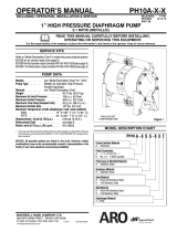
DIMENSIONAL DATA
651747-2-M FLUID HEATER
Figure 1
16-1/16”
(408.0 mm)
4-3/16”
(105.6 mm)
8-13/16”
(223.8 mm)
3-3/4”
(95.3 mm)
7-1/2”
(190.5 mm)
4-3/4”
(120.7 mm)
3/4 - 14 N.P.T.F.
1/2 - 14 N.P.T.F.
(Outlet)
1/2 - 14 N.P.T.F. (Inlet)
Mounting holes (hidden)
Thermometer - Do not over-
tighten. For orientation only.
0891
OPERATING PRECAUTIONS
•
Heed all warnings.
WARNING
Do not exceed 35 MPa (5000 p.s.i.) maximum.
WARNING
HIGH PRESSURE DEVICE. Improper usage of
this equipment could result in serious injury. The possibility of
injection into the flesh is a potential hazard. Never allow any
part of the human body to come in front of, or in direct contact
with, the material outlet. An injection injury can be serious. If
injection should occur, contact a qualified physician for imme -
diate treatment.
CAUTION
Electrical supply power to the heater must be off
during flushing operation.
CAUTION
Use only genuine Aro replacement parts to as-
sure compatible pressure rating and longest service life.
CAUTION
Do not remove cover when energized.
INGERSOLL RAND COMPANY LTD
209 NORTH MAIN STREET – BRYAN, OHIO 43506
(800) 495-0276
FAX(800) 892-6276
© 2010 CCN 15200561
www.ingersollrandproducts.com
FLUID HEATER DATA
Models 651747-2-M.......................
Wetted Parts Material Stainless Steel............
Volts AC 220......................
Amperes 8.3......................
Watts 2000.........................
Accuracy ±1.9_ C(3-1/2_ F)......................
Temperature Rise Above Ambient 38_ C (100_ F)...
Recovery Rate per Hour 56.8 liters (15 gallons)..........
Maximum Working Pressure 35 MPa (5000 p.s.i.).......
Maximum Temperature Range 16 - 121_ C (60 - 250_ F)......
Surface Temperature Code T3 (200_ C / 392_ F)........
Fluid Passage Diameter 9.4 mm (0.370”)...........
Fluid Passage Length 232.9 cm (91.7”)............
Fluid Passage Volume 0.162 lit. (9.86 in.
3
)............
Inlet / Outlet Port Size (female) 1/2 - 14 N.P.T.F. - 1.....
Weight 8.2kg(18lbs)........................
Environment Approval Group II 2 G Ex dII B T3............
CENELEC Standard
EN 60079-0 & EN 670079-1..............
Notified Body Certification TRL04ATEX11052........

Page2of4
651747-2-M
POWER SUPPLY AND INSTALLATION
Do not use neutral as earth ground. A single phase power / earth
ground is required. If this is not available, use a transformer to obtain
single phase power.
Provisions should be made for a quick disconnect or shut-off of all elec-
trical power to this unit.
All wiring must comply with all local and / or national electrical codes.
• Electrical codes that apply must be strictly adhered to. Failure to do
so may lead to shock hazard or serious injury.
• Some local electrical codes may require the installation of rigid con-
duit.
• The installer of this system assumes full responsibility for com-
pliance with these codes.
• Aro is not responsible for accidents resulting from improper installa-
tion of components or hardware.
• No electrical power should be in the system at the time the cover is
removed.
AIR AND LUBE REQUIREMENTS
Commonly used solvents and their lowest boiling points as pertains to
the Aro free flow system:
Hydrocarbons (Petroleum Naphthas)
Boiling Point _ F(_ C) k
VM & P 244 (118)
Mineral Spirits 314 (157)
Odorless Mineral Spirits 353 (178)
Aromatics (Terpenes)
Benzene 172 (78)
Toluene 230 (110)
Xylene 281 (138)
Gum Turpentine 311 (155)
Dipentene 347 (175)
Alcohols
Methanol 147 (64)
Isobutyl Alcohol 223 (106)
Nybutyl Alcohol 241 (116)
Keytones
MEK 174 (79)
Acetone 122 (50)
Diacetone 284 (140)
k International Critical Tables (ref.)
OPERATING INSTRUCTIONS
START-UP PROCEDURE
1. Fill the system with fluid.
2. Circulate the fluid thru the system.
CAUTION
Power should never be on when there is only sol-
vent in the system. Solvents can expand if there is no circula-
tion,causingexcessiveand hazardous pressure in thesystem.
3. Turn the power on.
4. Set the thermostat just below the boiling point of the lowest boiling
solvent in the coating material (see table above).
5. Allow fluid to circulate thru the heater for 5 - 10 minutes.
6. Readjust the thermostat as necessary.
To adjust the temperature, turn the knob:
a. Clockwise -- higher temperature
b. Counterclockwise -- lower temperature
SHUTTING THE SYSTEM OFF
1. Allow the fluid to circulate for 5 - 10 minutes after shutting the heater
off, to cool the system.
2. Always leave the solvent or fluid in the heater.
MAINTENANCE
NOTE: The (26) fluid track is a cast assembly and cannot be disas-
sembled for cleaning. Do not allow material to solidify inside the
heater. Flush the paint heater with the proper solvent immediately fol-
lowing each use.
CAUTION
Shut the electrical supply o ff and relieve all pres-
surefromthesystem before servicing anypartofthefluid heat-
er system.
CLEANING
1. When cleaning the fluid heater, use only solvents compatible with
the material being pumped.
2. The fluid heater should be flushed with solvent when changing me-
dias, or when it is not being used for a period of time.
NOTE: For other maintenance problems, see “Trouble Shooting”, page
4.
DISASSEMBLY
NOTE: The following procedure is for the repair of the (27) heater car-
tridge assembly or (24) thermostat.
1. Relieve all fluid pressure in the system.
2. Rotate the (19) adjusting knobcounterclockwisetothe“off” position.
3. Disconnect the power supply to the fluid heater assembly.
4. Disconnect the fluid lines.
5. Remove the six (2) cap screws.
6. Remove the (16) cover.
7. Remove the two (10) machine screws and (11) lockwashers from
the (15) housing, which retain the thermostat assembly.
8. Remove (as one unit) the (8) terminal block, (24) thermostat and (9)
mounting plate by carefully lifting it out and removing the power lead
wires (1 and 3) from the first two positions on the (8) terminal block
(refer to figure 3).
9. Remove the (27) heater cartridge assemblyleads fromthe (8) termi-
nal block third and fourth positions.
10. Carefully finish removing the assembly by pulling the thermostat
capillary tube out of the (26) fluid track body.
NOTE: Special care must be taken not to sharply bend or kink the capil-
lary tube which will ruin the thermostat. Do not use pliers or other tools
which may also damage the tube.
HEATER CARTRIDGE REMOVAL
1. Pull the (27) heater cartridge assembly from the (26) fluid track.
NOTE: If the (27) heater cartridge assembly does not easily come
out, do the following:
a. Remove the (28) pipe plug from the bottom of the (26) fluid
track.
b. Carefully drive the (27) heater cartridge assembly out thru
the top of the heater (toward the cover).
REASSEMBLY
1. Reassembly is done in the reverse order.
NOTE: When reinstalling the (16) cover, be certain the (19) adjusting
knob is turned out.
2. Rotate the adjusting knob clockwise out as far as it will go and turn it
back in carefully to align the slots with the thermostat.

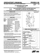
1 2 H3
4
5
6
7
81112
20
17 D18
15
26
28
H 25
23
24
Wiring Schematic
29
31
30
32
View A - A
A
A
H (25) Torque to 10 - 12 ft lbs (13.6 - 16.3 Nm).
D (17) Apply Loctite 242 to threads.
` Apply Crouse Hinds Sealing Compound or Appleton CO-4
Sealing Cement and allow to set before moving wires.
- Apply Dow Corning 340 Silicone Heat Sink Compound.
Z Apply Wat Lube
`
“B”
“C”
“B” Outlet (1/2 - 14 N.P.T.F. - 1)
“C” Inlet (1/2 - 14 N.P.T.F. - 1)
4
3
2
1
Figure 2
Figure 3
42.85 mm
(1.687”)
21
22
27 Z
Mounting Holes (2)
5/16 - 18 UNC -2B
12.7 mm (1/2”) deep
Input Line
(5) Green
(3) Red
(1) Black
(27) Heater Cartridge
(29) Heater Limiter
(24) Thermostat
109
13
14
16
19
1
2
3
4
33
-
4
34
651747-2-M Page3of4
PARTS LIST / 651747-2-M
Item Description (size) Qty Part No.
: 1 14 Gauge Wire (12” long, black) (1) 78140-XXX-X
2 Cap Screw (M8-1.25x30mm) (6) 93475-M
: 3 14 Gauge Wire (12” long, red) (1) 78141-XXX-X
4 Ring Terminal (3) 78143
: 5 14 Gauge Wire (7” l ong, green) (1) 78142-XXX-X
6 Machine Screw (#10 - 24 x 1/4”) (1) Y76-103-C
7 Cable Gland (3/4 - 14 P.T.F.) (1) 93473-M
8 Terminal Block (1) 92932
9 Mounting Plate (1) 93583-1
10 Machine Screw (#6-32x1/4”) (4) Y8-463-C
11 Lockwasher (#6) (4) Y1-6
12 Thermometer (0_ - 250_ F/-10_ - 120_ C) (1) 91696
13 Ground Screw (M5-0.8x10mm) (1) 93474-M
14 Rail (1) 93472-M
15 Housing (1) 92928-M
16 Cover (1) 93466-M
17 Machine Screw (#6-32x5/8”) (2) Y8-468-C
18 Nut (#6 - 32) (2) Y22-6-C
19 Adjusting Knob (1) 93586-1
20 Retaining Ring (1) 93471-M
21 Washer (1/4”) (1) Y13-4-C
22 Spring Washer (1) 93470-M
23 Spindle (1) 93467-M
24 Thermostat (16_ - 121_ C/60_ - 250_ F)
(20 amp. / 480 volt AC)
(1) 92972
25 Cap Screw (3/8” - 16 x 1-1/4”) (3) Y99-63
26 Fluid T rack (1) 92974
27 Heater Cartridge Assembly (+10% / -5%)
(230 / 240 volt AC, 27.36 Ohms)
(1) 66751-2
28 Pipe Plug (1/2 - 14 N.P.T.) (1) Y17-53
29 Heater Limiter (1) 92935
30 Terminal (2) 78035
: 31 14 Gauge Wire (6” long, black) (2) 78140-XXX-X
32 Terminal (4) 78034-1
33 Machine Screw (M4x5mm) (2) 93472- M6
34 Blanking Plug (3/4 - 14 N.P.T.) (1) 93476- M
: Available in bulk rolls only.

Page4of4
651747-2-M
TROUBLE SHOOTING
Fluid heater will not produce heat.
• No current to the heater unit.
Check the main power switch.
Check the power supply fuse, etc.
• Damaged thermostat.
Replace the thermostat.
• The heat limiter is burned out.
Replace the heat limiter.
• The heat element is burned out.
Replace the heater cartridge element.
The temperature of the material is too low.
• The voltage to the heater is too low.
Correct the wiring.
• The thermostat is damaged.
Replace the thermostat.
• The thermostat setting is wrong.
Adjust the thermostat.
• Material build-up inside the heater.
Clean the fluid heater and material lines.
• The material flow is too fast.
Reduce the material flow.
The temperature of the material is too high.
• The thermostat is damaged.
Replace the thermostat.
• Wrong setting on the thermostat.
Reset the thermostat.
The heater takes too long to heat the material.
• The voltage is too low.
Correct the wiring.
• Material build-up inside the heater.
Clean the fluid heater and material lines.
Inadequate material flow.
• Material build-up inside the heater.
Clean the fluid heater and material lines.
TYPICAL INSTALLATION
TYPICAL SINGLE HEATER
Figure 4
TYPICAL DUAL HEATER
“A”
“A”
“B” “B”
“C”
“C”
“A” = Material Outlet
“B” = Material Inlet
“C” = Power In
ACCESSORIES
66258 Mounting Bracket Assembly
Figure 5
11/16” (17.5 mm)
2-1/4”
(57.2 mm)
6” (152.4 mm)
1-11/16”
(42.9 mm)
3/8” dia. (9.5 mm) 6x
PN 97999-1052
/