Page is loading ...

3A2954D
EN
Instructions - Parts
VISCON
®
HF
High Flow, High Pressure Fluid Heater
For variable heating of viscous fluids.
Not approved for use in explosive atmospheres or hazardous locations.
7250 psi (50 MPa, 500 bar) Maximum Working Pressure
See page 2 for model numbers, descriptions, and approvals
information.
Important Safety Instructions
Read all warnings and instructions in this manual.
Save these instructions.
ti20051a
Thermostat
Controlled
Externally Controlled, RTD
Feedback Model

Models
2 3A2954D
Contents
Models ...................................2
Warnings .................................3
Installation ................................5
TypicalInstallationDrawing ................5
Component Identification ....................6
General Information ......................7
SelectingTubing .........................7
Mounting Heater .........................8
Fluid Connections and Accessories ..........9
Electrical Connections ...................10
RTD Temperature Connection .............10
Grounding .............................10
Operation ................................11
Pressure Relief Procedure ................11
Initial Flushing .........................11
Priming System .........................11
Setting Heater Control ...................12
AdjustingforSpraying ....................12
Maintenance ..............................13
Flushing ..............................13
Drain the Heater ........................13
Troubleshooting ...........................14
Repair ...................................16
Primary Thermostat & Probe ...............16
Overtemperature Switch ..................16
Control Knob ...........................18
Heater Core Removal and Fluid Passage
Unclogging .........................19
Heater Cartridges .......................20
RTD Sensor and Fitting Replacement ........21
Parts ....................................22
24P016 ...............................22
262853 ...............................24
Accessories ..............................26
TechnicalData ............................27
Performance Charts .....................28
Dimensions ............................29
Graco Standard Warranty ...................30
GracoInformation .........................30
Models
Model Series Description
VAC (50/60 Hz single phase) /
Watts / Amps
Approvals
24P016 C Thermostat Control 240 / 5400 / 22.5
262853 C
RTD, For Use With
External Digital Control
240 / 5400 / 22.5
9902471
Conforms to
UL Std. 499
CSA Std. 22.2 No. 88

Warnings
3A2954D 3
Warnings
The following warnings are for the setup, use, grounding, maintenance, and repair of this equipment. The exclama-
tion point symbol alerts you to a general warning and the hazard symbols refer to procedure-specific risks. When
these symbols appear in the body of this manual or on warning labels, refer back to these Warnings. Product-specific
hazard symbols and warnings not covered in this section may appear throughout the body of this manual where
applicable.
WARNING
ELECTRIC SHOCK HAZARD
This equipment must be grounded. Improper grounding, setup, or usage of the system can cause electric
shock.
• Turn off and disconnect power at main switch before disconnecting any cables and before servicing
or installing equipment.
• Connect only to grounded power source.
• All electrical wiring must be done by a qualified electrician and comply with all local codes and
regulations.
BURN HAZARD
Equipment surfaces and fluid that’s heated can become very hot during operation. To avoid severe burns:
• Do not touch hot fluid or equipment.
SKIN INJECTION HAZARD
High-pressure fluid from gun, hose leaks, or ruptured components will pierce skin. This may look like just
a cut, but it is a serious injury that can result in amputation. Get immediate surgical treatment.
• Do not spray without tip guard and trigger guard installed.
• Engage trigger lock when not spraying.
• Do not point gun at anyone or at any part of the body.
• Do not put your hand over the spray tip.
• Do not stop or deflect leaks with your hand, body, glove, or rag.
• Follow the Pressure Relief Procedure when you stop spraying and before cleaning, checking, or
servicing equipment.
• Tighten all fluid connections before operating the equipment.
• Check hoses and couplings daily. Replace worn or damaged parts immediately.
FIRE AND EXPLOSION HAZARD
Flammable fumes, such as solvent and paint fumes, in work area can ignite or explode. To help prevent
fire and explosion:
• Use equipment only in well ventilated area.
• Eliminate all ignition sources; such as pilot lights, cigarettes, portable electric lamps, and plastic drop
cloths (potential static arc).
• Keep work area free of debris, including solvent, rags and gasoline.
• Do not plug or unplug power cords, or turn power or light switches on or off when flammable fumes
are present.
• Ground all equipment in the work area. See Grounding instructions.
• Use only grounded hoses.
• Hold gun firmly to side of grounded pail when triggering into pail. Do not use pail liners unless they
are antistatic or conductive.
• Stop operation immediately if static sparking occurs or you feel a shock. Do not use equipment
until you identify and correct the problem.
• Keep a working fire extinguisher in the work area.

Warnings
4 3A2954D
TOXIC FLUID OR FUMES HAZARD
Toxic fluids or fumes can cause serious injury or death if splashed in the eyes or on skin, inhaled, or swal-
lowed.
• Read MSDSs to know the specific hazards of the fluids you are using.
• Store hazardous fluid in approved containers, and dispose of it according to applicable guidelines.
PERSONAL PROTECTIVE EQUIPMENT
Wear appropriate protective equipment when in the work area to help prevent serious injury, including
eye injury, hearing loss, inhalation of toxic fumes, and burns. This protective equipment includes but is not
limited to:
• Protective eyewear, and hearing protection.
• Respirators, protective clothing, and gloves as recommended by the fluid and solvent manufacturer
EQUIPMENT MISUSE HAZARD
Misuse can cause death or serious injury.
• Do not operate the unit when fatigued or under the influence of drugs or alcohol.
• Do not exceed the maximum working pressure or temperature rating of the lowest rated system
component. See Technical Data in all equipment manuals.
• Use fluids and solvents that are compatible with equipment wetted parts. See Technical Data in all
equipment manuals. Read fluid and solvent manufacturer’s warnings. For complete information about
your material, request MSDS from distributor or retailer.
• Do not leave the work area while equipment is energized or under pressure.
• Turn off all equipment and follow the Pressure Relief Procedure when equipment is not in use.
• Check equipment daily. Repair or replace worn or damaged parts immediately with genuine manu-
facturer’s replacement parts only.
• Do not alter or modify equipment. Alterations or modifications may void agency approvals and create
safety hazards.
• Make sure all equipment is rated and approved for the environment in which you are using it.
• Use equipment only for its intended purpose. Call your distributor for information.
• Route hoses and cables away from traffic areas, sharp edges, moving parts, and hot surfaces.
• Do not kink or over bend hoses or use hoses to pull equipment.
• Keep children and animals away from work area.
• Comply with all applicable safety regulations.
PRESSURIZED ALUMINUM PARTS HAZARD
Use of fluids that are incompatible with aluminum in pressurized equipment can cause serious chemical
reaction and equipment rupture. Failure to follow this warning can result in death, serious injury, or prop-
erty damage.
• Do not use 1,1,1-trichloroethane, methylene chloride, other halogenated hydrocarbon solvents or
fluids containing such solvents.
• Many other fluids may contain chemicals that can react with aluminum. Contact your material sup-
plier for compatibility.
THERMAL EXPANSION HAZARD
Fluids subjected to heat in confined spaces, including hoses, can create a rapid rise in pressure due to
the thermal expansion. Over-pressurization can result in equipment rupture and serious injury.
• Open a valve to relieve the fluid expansion during heating.
• Replace hoses proactively at regular intervals based on your operating conditions.
WARNING

Installation
3A2954D 5
Installation
Typical Installation Drawing
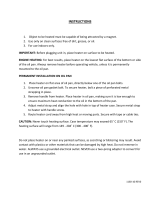
The typical installation drawing is only a guide. Your Graco distributor can assist in designing your system.
FIG. 1: Typical Installation – Heated Circulating System
Key:
A Bleed-type Master Air Valve
B Air Filter
C Air Regulator and Gauge
D Air Line Lubricator
E Pump Runaway Valve
F Ground Wire
G Pump
J Power Cable (not shown)
K Heater
L Fluid Filter
M Drain Valve
N Fluid Pressure Regulator
P Fluid Supply Line
Q Spray Gun
R Fluid Return Line
S Back Pressure Valve
T Fluid Shutoff Valve
U Director Valve
V Drain Back Tube
W Suction Tube
X Pressure Relief Valve
Y Whip End Hose
Z Air Supply Line
Q
05486-524
Y
R
S
P
N
L
M
T
U
XK
GF
EDCBA
V
W
Z
J

Component Identification
6 3A2954D
Component Identification
Key:
A1 Fluid Inlet
A2 Fluid Outlet
A3 Heater ON Indicator Light
A4 Temperature Control Knob (24P016 Only)
A5 Temperature Gauge (24P016 Only)
A6 Optional External RTD Feedback Port (262853 Only)
A7 Optional Inlet Ports (front and bottom)
A8 Optional Outlet Ports (one on outlet manifold and one on
opposite side of heater)
ti20051a
Thermostat
Controlled Model
Externally Controlled, RTD
Feedback Model
A2
A2
A1
A5
A1
A6, A8
A3
A3
A4
A7
A8
A8
A7

Component Identification
3A2954D 7
General Information Selecting Tubing
Fluid loses some heat through the tubing or hose
between the heater and spray gun. Locate heater close
to the spray area to minimize heat loss through plumb-
ing.
The chart in FIG. 2 shows a heat loss curve for 3 com-
mon types of tubing.
Chart Notes:
• Higher flow rates have less heat loss.
• Foam-insulated steel tubing and high pressure air-
less paint hose retain heat best. Insulated tubing
and hose are more expensive, but higher costs are
commonly offset by lower operating costs.
• Select system components that meet temperature
and pressure ratings listed in Technical Data,
page 27. The heater’s normal output range is
adjustable from 84-220°F (29-104°C).
• To prevent fire and explosion, locate heater away
from all flammable materials and where operators
will not come in contact with hot metal surfaces.
• To avoid burns, insulate and/or label lines and
components exiting heater that may become hot.
FIG. 2: Typical Temperature Drop
0
1
2
3
4
5
6
0 0 .5 1 1 .5 2 2.5 3
(1)
(2)
(3)
(4)
(5)
(6)
(7)
(8)
(9)
(0.1) (0.2) (0.3 ) (0.4 ) (0.5) (0.6 ) (0.7) (0.8)
Heat Loss Curve: 70°F (21°C) Ambient
Typical Fluid Temperature Drop
Flow Rate
(20 ft.) 6.1 m steel tube
Fluid: (130° F) 54° C
(20 ft.) 6.1 m steel tube
(3/8 in.) 9 mm foam insulation
Fluid: (110° F) 43° C
(20 ft.) 6.1 m airless paint hose
Fluid: (110° F) 43° C
(°F) °C
LPM
(GPM)

Component Identification
8 3A2954D
Mounting Heater
NOTE: The Viscon HF heaters will mount anywhere a
Viscon HP heater was previously mounted. See the
dimensions listed for accessory bracket 192585 on
page 26 and the heater dimensions shown on page 29.
NOTE: Heater controls must be easily accessible.
NOTE: The mounting surface must be able to support
the weight of the heater and fluid and any stress caused
during operation.
Wall Mounting
NOTE: Use wall bracket as a template to mark bolt
holes.
Accessory Bracket 192585
(FIG.3)
1. Use lockwashers and M8 bolts (AA) of appropriate
length, not supplied, to mount bracket.
2. Install two screws (74) through spacer block and
into top two heater mounting holes until they are
about 1/8 in. (3 mm) from fully installed.
3. Lift heater and slide two screw heads into bracket
slots.
4. Install u-bracket (78) around heater and install
remaining 2 nuts (90). Tighten all nuts and bolts.
Cart Mounting
(FIG.4)
NOTE: For a 2.5 in. square tube frame cart you need to
have 2 each of cart mounting bar 183485 (CC) and
clamp 183484 (BB). See Accessories, page 26, to
order.
Place clamps (BB) around the cart vertical post (DD)
and secure to the heater mounting bars (CC) with bolts
(74) and nuts (90).
FIG. 3: Accessory Bracket 192585
ti20054a
AA
74
90
78
FIG.4
74
CC
BB
DD
90
ti20055a

Component Identification
3A2954D 9
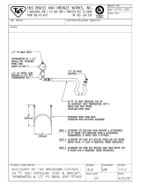
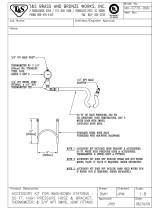
Fluid Connections and
Accessories
(FIG.5)
1. Install a fluid shutoff valve (T) in the heater’s
3/4 in. npt(m) fluid inlet. Do not overtighten. Connect
the fluid supply line to the valve.
To handle fluid expansion caused by heat:
• Use flexible hoses between heater and gun.
• Install a properly sized accumulator down-
stream from the heater.
• Install a pressure relief valve (X) pre-set to
relieve pressure when it exceeds the system
maximum working pressure.
2. If feeding an airless spray gun, install a fluid
filter (L), drain valve (M), and fluid pressure regula-
tor (N) near the heater’s 3/4-14 npt(f) fluid outlet.
Then connect the fluid outlet line.
To prevent serious injury caused by component or
equipment rupture:
• Never install a shutoff device between the heater
and gun as this will trap the heated fluid and not
allow for expansion.
• Never use a fluid regulator as a shutoff device if it
is installed between the heater and gun
• Provide a means for adequately handling fluid
expansion caused by heat.
NOTICE
The RTD sensor must always be mounted on the out-
let side of housing (67). If you plumb the outlet to the
left side, swap position of sensor (88) and plug (82).
FIG. 5: Fluid Connections and Accessories
ti20056a
T
X
N
L
M

Component Identification
10 3A2954D
Electrical Connections
Requirements For All Installations
• The power supply must not exceed heater voltage
and amperage. See Models, page 2.
• Conductors used for supply connection must be
suitable for at least 221°F (105°C). An intermediate
Type “e” junction may be required.
• Branch circuit breaker over-current protection must
be used. The recommended branch circuit breaker
size is 30 amps.
• Connections are made through the strain relief cord
grip (87). It will accept cords with an outside diame-
ter of 0.51-0.71 in. (13-18 mm).
• Make your ground connection to the green ground
lug inside the control head.
• Make your power connections to the single white
and black wires which have loose ends in the control
head. Refer to the applicable schematic on page 15.
RTD Temperature Connection
(Model 262853 Only)
A separate smaller cord grip is provided to bring a cable
and connector into the M8 4-pin connection inside the
heater. Refer to the applicable schematic on page 15
and the Technical Data on page 27.
Grounding
Wire the heater to a properly grounded power supply
through the electrical connections and grounding
screw (8). In a mobile installation, also ground the truck
or trailer to a true earth ground.
Heater installation must be in compliance with all
applicable local codes and regulations. This equip-
ment must be grounded. Improper grounding, setup,
or usage of the system can cause electric shock. All
electrical wiring must be done by a qualified electri-
cian and comply with all local codes and regulations.
NOTICE
To help prevent damage, avoid spilling liquids onto
electrical components and never operate with the
cover removed or screws missing.
The equipment must be grounded to reduce the risk
of static sparking and electric shock. Electric or static
sparking can cause fumes to ignite or explode.
Improper grounding can cause electric shock.
Grounding provides an escape wire for the electric
current.

Operation
3A2954D 11
Operation
Pressure Relief Procedure
Follow the Pressure Relief Procedure whenever
you see this symbol.
Follow Pressure Relief Procedure when you stop
spraying, and before cleaning, checking, or servicing
equipment.
1. Engage the gun trigger lock.
2. Shut off main power to the heater.
3. Circulate fluid for at least 10 minutes to cool the
heated fluid and heater.
4. Shut off all air and fluid supplies.
5. Disengage the gun trigger lock.
6. Hold a metal part of the gun firmly to a grounded
metal pail, and trigger the gun to relieve pressure.
7. Engage the gun trigger lock.
Initial Flushing
The heater was tested with lightweight oil, which needs
to be flushed out before using the equipment. Use a
compatible solvent, and follow flushing instructions in
your fluid supply and spray gun manual.
Priming System
(Refer to FIG.1,page5)
1. Do not turn on the heater yet.
2. If using an airless spray gun, do not install a spray
tip yet.
3. Start the pump according to the instructions sup-
plied with it.
4. Turn the system director valve (U) to circulate, and
circulate fluid for several minutes.
5. Open the spray gun (Q) at the last outlet to prime
the line. Repeat for all gun stations.
6. Engage the gun trigger lock.
7. Shut off the air supply to the pump.
8. Perform Pressure Relief Procedure.
9. Install the gun spray tip.
This equipment stays pressurized until pressure is
manually relieved. To help prevent serious injury from
pressurized fluid, such as skin injection, splashing
fluid and moving parts, follow the Pressure Relief
Procedure when you stop spraying and before
cleaning, checking, or servicing the equipment.
To avoid skin injection, do not point gun at anyone or
at any part of the body. To avoid fire and explosion,
ensure main power is off and heater is cool before
flushing. Do not turn on heater until fluid lines are
clear of solvent.

Operation
12 3A2954D
Setting Heater Control
(Refer to FIG.6)
This procedure applies to model 24P016 only. Heater
262853 with RTD control has no adjustments to make
on the heater, it requires use of an external temperature
controller.
1. Set the heater control knob (33) to a trial setpoint of
4or5.
2. Start the pump and circulate fluid through the sys-
tem at a very low flow rate of about 10-12 oz/min
(0.30-0.35 liter/min).
3. After the indicator light turns off: read the tempera-
ture on the thermometer (2). If it does not match the
desired temperature, adjust the setpoint.
Adjusting for Spraying
1. Adjust pump pressure and heater setpoint to the
lowest settings needed for good fluid atomization.
2. Set all system back pressure valves (S - FIG.1on
page 5) to maintain even fluid pressure at all gun
stations.
FIG. 6: Setting Heater Control
33
05549-524
2
NOTICE
Operating the heater at its highest setting of over
180°F (82°C) for long periods of time decreases the
heater life and can cause fluid to dry out which can
cause heater clogging and a poor spray pattern.

Maintenance
3A2954D 13
Maintenance
Flushing
Clogged fluid passages reduce heating efficiency, flow
rate, and pressure. Flush or clean whenever a change in
heating efficiency, flow rate, or pressure is noticed.
1. Follow Pressure Relief Procedure, page 11.
2. Ensure main power is off and heater is cool before
flushing. Use a compatible solvent, and follow flush-
ing instructions in your fluid supply and spray gun
manual. Do not turn on heater until fluid lines are
clear of solvent.
Drain the Heater
(FIG.7)
1. Follow Pressure Relief Procedure, page 11.
2. Remove heater inlet and outlet fittings or pipe plugs.
Have a container ready to catch the fluid.
To avoid fire and explosion, ensure main power is off
and heater is cool before flushing. Do not turn on
heater until fluid lines are clear of solvent.
FIG. 7: Drain the Heater
ti20057a
Outlet
Inlet

Troubleshooting
14 3A2954D
Troubleshooting
Problem Cause Solution
Heater will not heat. No current. Check circuit and fuses.
Overtemperature switch (10) tripped. • Check continuity of
overtemperature switch. If
circuit is open, press red reset
switch and re-check.
Determine why switch opened
before restarting.
• Model 24P016 only: check that
the thermostat (24) is open
when the knob is turned to the
left and closed when turned to
the right.
Burned out heater cartridges (81). Replace cartridges.
Temperature too low. Fluid requires more warm-up time. Increase warm-up time.
Wrong temperature setting. Adjust setting, page 12.
Flow rate too high. Reduce flow rate or use 2 heaters.
Clogged fluid passages. Heater Core Removal and Fluid
Passage Unclogging, page 19.
One of the two heater cartridges (81)
failed.
Check each cartridge for a resistance
of approximately 21 ohms. The pair
in parallel should have a resistance
of approximately 10.7 ohms. See
Heater Cartridges on page 20.
Temperature too high. Wrong temperature setting. Adjust setting, page 12.
Failed primary thermostat (24). Replace, page 16.
High fluctuating temperatures, about
220-250°F (104-120°C) at 0.1 GPM.
Primary thermostat (24) contacts
sticking.
Replace thermostat (24), page 16.
Too much pressure drop or fluid will
not flow.
Flow rate too high. Reduce flow rate or use 2 heaters.
Clogged fluid passages. Flush or clean, page 13.
Heater fittings leak. Loose or damaged fittings. Tighten or replace fittings.
Heater temperature rises far beyond
the setpoint temperature during heat-
ing
Model 262853 only: RTD sensor (88)
is installed too far into fluid path. Sen-
sor does not sense aluminum core.
Replace sensor (88) and compres-
sion fitting (72). See page 21.
Heater core is dirty or has baked on
material.
Disassemble and clean all parts that
come in contact with material.

Troubleshooting
3A2954D 15
NOTE: See the Parts illustration that applies to your heater on page 22 or 24.
FIG. 8: Electrical Schematic - 262853 Heater with RTD
87
37
10
37
89
89
96
53
81
42, 88
ti20062a
WHITE
BLACK
260°F
RTD Sensor
(1000 ohm)
4
1
3
RTD Pin Wire Color Signal
1 Red Excitation
2 --- ---
3 White RTD Element
4 Red Lead Ohms
FIG. 9: Electrical Schematic - 24P016 Heater with Thermostat
ti20063a
87
98
10
98
89
89
53
81
24
9737
260°F
WHITE
BLACK

Repair
16 3A2954D
Repair
Primary Thermostat & Probe
(Model 24P016 Only, see FIG.10onpage17)
1. Perform Pressure Relief Procedure, page 11.
2. Remove screws (52) then remove housing
cover (18).
3. Loosen screws (25) that secure thermostat in place.
4. Remove wires from the primary thermostat termi-
nals (FF).
5. Loosen setscrew (26) in switch shaft (28)
6. Pull thermostat probe (EE) out of heater block.
7. Remove thermostat (24) from housing (1).
8. Remove screw standoff (35) with washer (27).
9. Remove bracket from thermostat (24) and secure to
new thermostat.
10. Liberally apply thermal lubricant (part no. 110009) to
probe (EE) of new thermostat (24). Loop capillary
tube (GG) several times and wrap the loops with tie
strap (42-not shown). Insert probe in the heater
block.
11. Continue reassembling in reverse order of disas-
sembly. See the following Reassembly Notes sec-
tion.
Overtemperature Switch
NOTE: This switch is a manual reset type. Press the red
button to reset the switch. Check for continuity across
the contacts. If the switch tripped, always determine the
cause before returning the heater to service.
1. Follow Pressure Relief Procedure, page 11.
2. Remove screws (52) then remove housing
cover (18).
3. Unplug wires from tabs (HH) on switch.
4. Remove the two screws (16) securing the switch
then remove the switch (10).
5. Liberally apply thermal lubricant (part no. 110009) to
the bottom of the thermostat switch and reinstall it in
reverse order of disassembly.
Reassembly Notes
• Refer to FIG.8orFIG. 9 for wiring connections.
• Make sure gasket (47) is installed and aligned with
electrical housing screw holes.
• Secure cover (18) with screws (52). Torque screws
to 89 in-lb (10 N•m).
To avoid burns, electric shock, and skin injection,
make sure the main power is OFF, heater is cool, and
pressure is relieved before repairing.
NOTICE
To avoid damaging capillary tube (GG) of the thermo-
stat, which can cause heater malfunction, do not kink
or nick the tube.
To avoid shorting out the heater, do not allow capillary
tube to contact the terminals on switch (10) or
thermostat (24). Follow step 10, below.

Repair
3A2954D 17
FIG. 10: Thermostat Repair - 24P016
52
47
54
51
50
48
20
28
29
33
3030
12
35
27
18
EE
FF (not visible in current view)
24
25
26
HH
81
25
10
16
GG
JJ
24
FIG. 11: Sensor Repair - 262853
47
52
1
54
51
50
48
20
18
10
25
HH
16
88
72

Repair
18 3A2954D
Control Knob
This procedure applies to heater 24P016 only. See the
Parts illustration on page 22.
1. Follow Pressure Relief Procedure, page 11.
2. Turn control knob (33) to setpoint 1.
3. Loosen the control knob setscrew (30).
4. Remove control knob.
5. Remove adjusting knob (12) from the control knob
and press fit it onto the new control knob. Check the
grommet (29) and replace if worn.
6. Position new knob so setpoint 1 aligns with the
12 o’clock position and the knob is about 1/16 in.
(1 mm) away from the housing. Install and tighten
setscrew (30).

Repair
3A2954D 19
Heater Core Removal and Fluid
Passage Unclogging
The heater core (68) can be removed for thorough
cleaning or replacement. See the Parts illustration that
applies to your heater on page 22 or 24.
1. Follow Pressure Relief Procedure, page 11.
2. Disconnect power.
3. Drain the Heater, page 13.
4. Loosen set screws (83) from bottom inlet housing
witha3/16in.hexkey.
5. Unscrew bottom inlet housing (65).
6. Remove nuts (90) then remove cylinder u-bolt
clamp (78).
7. Loosen set screws (83) on upper fluid housing (67).
8. Unscrew cylinder (66). Pull down to remove.
9. Remove screws (52) then remove cover (18).
10. On model 262853 only, remove RTD sensor (88).
Loosen nut on compression fitting (72). Pull nut and
sensor straight up out of heater.
11. Remove 4 screws (71) from top of plate (69).
12. Disconnect heater cartridge (81) wire leads from
wire nuts (89).
13. Pull heater core straight down out of the upper
housing (67).
14. Use a wire brush to clean outside fluid passages
until bare aluminum is visible.
NOTE: Model 24P016 Only: The capillary bulb/tube
from the thermostat (24) will slowly pull out of its hole in
the core (68). The heater core wires will pull down
through plate (69).
Reassembly Notes
• Always replace o-rings (70, 76, and 79).
• Refer to FIG.10orFIG. 11 on page 17 for wiring
connections.
• Model 262853 only: Make sure the core (68) is
aligned with the plug (82) pin in housing (67).
• Make sure gasket (47) is installed and aligned with
electrical housing screw holes.
• Secure cover (18) with screws (52). Torque screws
to 85-90 in-lb (10 N•m).
FIG.12
NOTICE
On model 262853 only, to prevent damaging the RTD
sensor (72), do not rotate the core (68) when perform-
ing the following step.
ti20065a
90
78
66
68
65
76
83
67
76
83
83
79
70
NOTICE
To prevent damage to sensors and wiring, do not turn
core (68). The core pushes straight down out of
housing (67).

Repair
20 3A2954D
Heater Cartridges
See Parts illustration that applies to your heater on
page 22 or 24.
1. Follow Pressure Relief Procedure, page 11.
2. Disconnect power.
3. Drain the Heater, page 13.
4. Perform Heater Core Removal and Fluid Passage
Unclogging procedure on page 19. This includes
removing the inlet housing (65).
5. With the inlet housing removed, remove 5
screws (52) and cover (18).
6. Disconnect wires from heater cartridges (81).
7. Remove pipe plug (95) and springs (31) from bot-
tom of core (68).
8. Use a 3/8 in. (10 mm) rod to push each cartridge out
of the top of the core.
9. Wire new cartridges per FIG.8orFIG. 9, page 15.
/