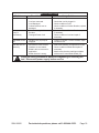
Chicago Electric 66660 Set Up And Operating Instructions Manual
- Category
- Power tools
- Type
- Set Up And Operating Instructions Manual
Chicago Electric 66660
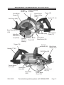
The Chicago Electric 66660 is a 7-1/4" Worm Gear Circular Saw designed for a variety of cutting applications. Its powerful motor and durable construction make it ideal for both professional and DIY projects.
Capabilities:
- Accurate Cuts: The saw features a precision-ground blade that ensures clean, accurate cuts in a variety of materials, including wood, metal, and plastic.
- Versatile Cutting Angles: The adjustable base allows for bevel cuts up to 45 degrees, providing versatility for angled cuts and miters.
- Depth Control: The adjustable cutting depth allows for precise control of the depth of cut, ensuring consistent results.
Chicago Electric 66660
The Chicago Electric 66660 is a 7-1/4" Worm Gear Circular Saw designed for a variety of cutting applications. Its powerful motor and durable construction make it ideal for both professional and DIY projects.
Capabilities:
- Accurate Cuts: The saw features a precision-ground blade that ensures clean, accurate cuts in a variety of materials, including wood, metal, and plastic.
- Versatile Cutting Angles: The adjustable base allows for bevel cuts up to 45 degrees, providing versatility for angled cuts and miters.
- Depth Control: The adjustable cutting depth allows for precise control of the depth of cut, ensuring consistent results.


-
 1
1
-
 2
2
-
 3
3
-
 4
4
-
 5
5
-
 6
6
-
 7
7
-
 8
8
-
 9
9
-
 10
10
-
 11
11
-
 12
12
-
 13
13
-
 14
14
-
 15
15
-
 16
16
-
 17
17
-
 18
18
-
 19
19
-
 20
20
-
 21
21
-
 22
22


Chicago Electric 66660 Set Up And Operating Instructions Manual
- Category
- Power tools
- Type
- Set Up And Operating Instructions Manual
Chicago Electric 66660
The Chicago Electric 66660 is a 7-1/4" Worm Gear Circular Saw designed for a variety of cutting applications. Its powerful motor and durable construction make it ideal for both professional and DIY projects.
Capabilities:
- Accurate Cuts: The saw features a precision-ground blade that ensures clean, accurate cuts in a variety of materials, including wood, metal, and plastic.
- Versatile Cutting Angles: The adjustable base allows for bevel cuts up to 45 degrees, providing versatility for angled cuts and miters.
- Depth Control: The adjustable cutting depth allows for precise control of the depth of cut, ensuring consistent results.
Ask a question and I''ll find the answer in the document
Finding information in a document is now easier with AI
Related papers
-
Chicago Electric 96635 Set Up And Operating Instructions Manual
-
-
-
-
-
-
-
-
-
Other documents
-
CHICAGO 67537 Set Up And Operating Instructions Manual
-
Harbor Freight Tools 4095 User manual
-
-
Bunker Hill Security 95318 Owner's manual
-
Central Machinery 93491 Assembly And Operating Instructions Manual
-
2Wire 94245 Owner's manual
-
-
-
-
Drill Master 93827 User manual