Page is loading ...

12” TABLE SAW
WITH RIP FENCE
Model 93491
ASSEMBLY AND OPERATING INSTRUCTIONS
3491 Mission Oaks Blvd., Camarillo, CA 93011
Visit our Web site at: http://www.harborfreight.com
Copyright
©
2006 by Harbor Freight Tools
®
. All rights reserved. No portion of this manual
or any artwork contained herein may be reproduced in any shape or form without the
express written consent of Harbor Freight Tools.
For technical questions, please call 1-800-444-3353.
®
TO PREVENT SERIOUS INJURY,
READ AND UNDERSTAND ALL WARNINGS
AND INSTRUCTIONS BEFORE USE.
Due to continuing improvements, actual product may differ slightly from the product described herein.

SKU 93491 For technical questions, please call 1-800-444-3353. Page 2
Contents
PRODUCT SPECIFICATIONS ....................................................................................... 3
GENERAL SAFETY RULES ......................................................................................... 3
Specific Safety Rules.......................................................................................................................... 6
Grounding ..........................................................................................................................................10
Extension Cords ................................................................................................................................11
Symbology .........................................................................................................................................12
UNPACKING................................................................................................................. 13
TABLE SAW FEATURES ............................................................................................ 13
ASSEMBLY INSTRUCTIONS ...................................................................................... 13
To Assemble The Stand:....................................................................................................................14
To Attach The Saw Table To The Stand: ............................................................................................15
To Attach The Saw Table Extensions: ...............................................................................................17
To Attach The Rear Rail: ....................................................................................................................18
To Attach The Front Rail: ...................................................................................................................19
To Align The Rip Fence And Front Rail: ...........................................................................................20
To Attach The Blade Guard: ..............................................................................................................21
To Check The Throat Plate For Proper Alignment: ..........................................................................23
To Check Rip Fence And Saw Blade Alignment: .............................................................................24
To Align The Riving Knife With The Saw Blade:...............................................................................25
To Replace The Saw Blade: ...............................................................................................................27
To Parallel The Saw Blade To The Miter Gauge Groove: .................................................................28
To Set The Bevel Stops And Indicator: .............................................................................................31
To Adjust The Miter Gauge: ...............................................................................................................32
Removing And Replacing The Throat Plate: ....................................................................................33
OPERATING INSTRUCTIONS..................................................................................... 34
Cutting Aids: ......................................................................................................................................34
Resetting The Thermal Overload Protector: .....................................................................................35
The Power Switch: .............................................................................................................................36
Making A Cross Cut: ..........................................................................................................................36
Making A Rip Cut: ..............................................................................................................................38
Making A Miter Cut: ...........................................................................................................................39
Making A Bevel Cross Cut:................................................................................................................40
Making A Bevel Rip Cut:....................................................................................................................42
Making A Compound (Bevel) Miter Cut: ...........................................................................................43
Making A Large Panel Cut:................................................................................................................44
Making A Dado Cut: ...........................................................................................................................46
INSPECTION, MAINTENANCE, AND CLEANING ...................................................... 46
TROUBLESHOOTING.................................................................................................. 49
PARTS LISTS AND DIAGRAMS ................................................................................. 51
Parts List A & Assembly Diagram A .................................................................................................51
Parts List B & Assembly Diagram B .................................................................................................52
Parts List C ........................................................................................................................................53
Assembly Diagram C .........................................................................................................................54
Parts List D & Assembly Diagram D .................................................................................................55
Parts List E & Assembly Diagram E .................................................................................................56
Parts List F & Assembly Diagram F..................................................................................................57
Parts List G & Assembly Diagram G.................................................................................................58
Parts List H & Assembly Diagram H .................................................................................................59
Parts List I ..........................................................................................................................................60
Assembly Diagram I ..........................................................................................................................61
WARRANTY................................................................................................................. 62

SKU 93491 For technical questions, please call 1-800-444-3353. Page 3
PRODUCT SPECIFICATIONS
SAVE THIS MANUAL
You will need this manual for the safety warnings and precautions, assembly, operating,
inspection, maintenance and cleaning procedures, parts list and assembly diagram.
Keep your invoice with this manual. Write the invoice number on the inside of the
front cover. Keep this manual and invoice in a safe and dry place for future reference.
GENERAL SAFETY RULES
WARNING!
READ AND UNDERSTAND ALL INSTRUCTIONS
Failure to follow all instructions listed below may result in
electric shock, fire, and/or serious injury.
SAVE THESE INSTRUCTIONS
WORK AREA
1. Keep your work area clean and well lit. Cluttered benches and dark areas
invite accidents.
2. Do not operate power tools in explosive atmospheres, such as in the
presence of flammable liquids, gases, or dust. Power tools create
sparks which may ignite the dust or fumes.
3. Keep bystanders, children, and visitors away while operating a power tool.
Distractions can cause you to lose control. Protect others in the work area from
debris such as chips and sparks. Provide barriers or shields as needed.
Item Description
Electrical Requirements 220 VAC / 60 Hz / 5.25 No Load AMPs / 3 HP / Single Phase / 3500 RPM
Power Switch Type: 2- Position Rocker Switch w/Pull Out Safety Lock-Off
Circuit Breaker Type: Thermal Overload Protection w/Motor Reset Button
Required Power Cord Plug Type: 3-Prong, 220 VAC, Polarized, Twist-Lock (Not Included)
Saw Blade Type 12” Diameter, 40 Teeth, Carbide Tipped, 1” Arbor Hole (Included)
Blade rated at 5000 RPM maximum
Cutting Depth Capacity 4-1/8” @ 0° Bevel / 2-7/8” @ 45° Bevel
Angle Cutting Capacity 0° ~ 60° (Left & Right – Miter Gauge) / 0° ~ 45° (Bevel – Blade Tilt)
Table Dimensions 31-1/2” L x 46-3/4” W x 1-1/2” Thick (w/Extensions)
Stand Dimensions 30 L x 26-1/2” W x 23” H (w/Adjustable Leveling Feet)
Spindle Size & Thread 1” Diameter / 16mm x 2.00
Miter Gauge Size 4” L x 7” W x 4” High (Including Handle) / 14-3/8” L x 3/4” W x 3/8” Thick Slide Bar
Rip Fence Size 41” L x 2-1/4” W x 2-3/4” H
Miter Gauge Scale 0° ~ 60° Left & Right (In 1° Increments)
Rip Fence Scale 0” ~ 23” (Left) / 0” ~ 25” (Right)
Dust Port Size 2-1/4” Diameter
V-Belt Size 44” Circumference x ½” Wide
Unit Weight 309.6 Pounds
IMPORTANT: This Table Saw is not equipped with the proper size Throat Plate and Spindle to
perform dado cuts. Do not attempt to alter the Table Saw components to perform dado cuts.

SKU 93491 For technical questions, please call 1-800-444-3353. Page 4
ELECTRICAL SAFETY
4. Grounded tools must be plugged into an outlet properly installed and
grounded in accordance with all codes and ordinances. Never remove the
grounding prong or modify the plug in any way. Do not use any adapter
plugs. Check with a qualified electrician if you are in doubt as to whether
the outlet is properly grounded. If the tools should electrically malfunction or
break down, grounding provides a low resistance path to carry electricity away
from the user.
5. Avoid body contact with grounded surfaces such as pipes, radiators,
ranges, and refrigerators. There is an increased risk of electric shock if your
body is grounded.
6. Do not expose power tools to rain or wet conditions. Water entering a power
tool will increase the risk of electric shock.
7. Do not abuse the Power Cord. Never use the Power Cord to carry the tools
or pull the Plug from an outlet. Keep the Power Cord away from heat, oil,
sharp edges, or moving parts. Replace damaged Power Cords immediately.
Damaged Power Cords increase the risk of electric shock.
8. When operating a power tool outside, use an outdoor extension cord
marked “W-A” or “W”. These extension cords are rated for outdoor use, and
reduce the risk of electric shock.
PERSONAL SAFETY
9. Stay alert. Watch what you are doing, and use common sense when
operating a power tool. Do not use a power tool while tired or under the
influence of drugs, alcohol, or medication. A moment of inattention while
operating power tools may result in serious personal injury.
10. Dress properly. Do not wear loose clothing or jewelry. Contain long hair.
Keep your hair, clothing, and gloves away from moving parts. Loose
clothes, jewelry, or long hair can be caught in moving parts.
11. Avoid accidental starting. Be sure the Power Switch is off before plugging
in. Carrying power tools with your finger on the Power Switch, or plugging in
power tools with the Power Switch on, invites accidents.

SKU 93491 For technical questions, please call 1-800-444-3353. Page 5
12. Remove adjusting keys or wrenches before turning the power tool on. A
wrench or a key that is left attached to a rotating part of the power tool may result
in personal injury.
13. Do not overreach. Keep proper footing and balance at all times. Proper
footing and balance enables better control of the power tool in unexpected
situations.
14. Always wear eye, hearing, and breathing protection. Wear ANSI
approved safety impact goggles, ANSI-approved hearing protectors, and
ANSI-approved dust mask or respirator when using this product. Non-skid
safety shoes, hard hat, or hearing protection must be used for appropriate
conditions.
TOOL USE AND CARE
15. Use clamps (not included) or other practical ways to secure and support
the workpiece to a stable platform. Holding the work by hand or against your
body is unstable and may lead to loss of control.
16. Do not force the tool. Use the correct tool for your application. The correct
tool will do the job better and safer at the rate for which it is designed.
17. Do not use the power tool if the Power Switch does not turn it on or off.
Any tool that cannot be controlled with the Power Switch is dangerous and must
be replaced.
18. Disconnect the Power Cord Plug from the power source before making any
adjustments, changing accessories, or storing the tool. Such preventive
safety measures reduce the risk of starting the tool accidentally.
19. Store idle tools out of reach of children and other untrained persons. Tools
are dangerous in the hands of untrained users.
20. Maintain tools with care. Keep cutting tools sharp and clean. Properly
maintained tools with a sharp cutting edge are less likely to bind and are easier
to control. Do not use a damaged tool. Tag damaged tools “Do not use” until
repaired.
21. Check for misalignment or binding of moving parts, breakage of parts, and
any other condition that may affect the tool’s operation. If damaged, have
the tool serviced before using. Many accidents are caused by poorly
maintained tools.

SKU 93491 For technical questions, please call 1-800-444-3353. Page 6
22. Use only accessories that are recommended by the manufacturer for your
model. Accessories that may be suitable for one tool may become hazardous
when used on another tool.
SERVICE
23. Tool service must be performed only by qualified repair personnel. Service
or maintenance performed by unqualified personnel could result in a risk of injury.
24. When servicing a tool, use only identical replacement parts. Follow
instructions in the
“Inspection, Maintenance, And Cleaning”
section of this
manual. Use of unauthorized parts or failure to follow maintenance instructions
may create a risk of electric shock or injury.
SPECIFIC SAFETY RULES
1. Ground this product. This Table Saw requires the attachment and use of a UL
approved, 220 volt, grounded, 3-prong, electrical Power Cord Plug (not included).
Only a qualified electrician should install the Power Cord Plug. Never remove the
grounding prong or modify the Power Cord Plug in any way. Do not use adapter
plugs with this product. To comply with the National Electric Code, and to provide
additional protection from the risk of electrical shock, this product should only be
connected to a 220 volt, 3-hole outlet that is protected by a Ground Fault Circuit
Interrupter (GFCI). (See Figure A, page 11.)
2. Maintain labels and nameplates on the Table Saw. These carry important
information. If unreadable or missing, contact Harbor Freight Tools for a
replacement.
3. Avoid unintentional starting. Make sure you are prepared to begin work
before turning on the Table Saw.
4. Do not force the Table Saw. This tool will do the work better and safer at
the speed and capacity for which it was designed. Do not force the Saw Blade
into the workpiece being cut.
5. WARNING! Keep hands and fingers away from cutting area and Saw Blade. Use
a “push stick” (not included) if necessary.
6. Never leave the Table Saw unattended when it is plugged into an
electrical outlet. Turn off the tool, and unplug it from its electrical outlet before
leaving.

SKU 93491 For technical questions, please call 1-800-444-3353. Page 7
7. Always use Saw Blades with a 12” diameter, 1” round arbor hole, and rated
at 3500 RPM or greater. Saw Blades that do not match the mounting hardware
of the Table Saw or that are rated less than the required minimum RPM will run
eccentrically; possibly causing loss of control.
8. Make sure the Table Saw is located on a flat, level, sturdy surface capable
of supporting the weight of the Saw and workpieces.
9. Do not use the Table Saw for cutting metals or for cutting curves. This will
cause the Saw Blade to break and/or reduce its service life.
10. Make sure the Table of the Table Saw and surrounding area are clear with
the exception of the workpiece to be cut.
11. Before using the Table Saw, check to make sure the Saw Blade is prop-
erly mounted on the Saw Spindle. Make sure the Saw Blade is balanced, and
is not cracked or bent.
12. Industrial applications must follow OSHA guidelines.
13. Never stand on the Table Saw. Serious injury could result if the Table Saw
is tipped or if the rotating Saw Blade is accidently contacted.
14. Never attempt to cut more than one workpiece at a time.
15. Never attempt to cut freehand. Make sure the workpiece to be cut is pressed
firmly against the Table.
16. When cutting a large workpiece, make sure its entire length is properly
supported. If necessary, use a roller stand (not included).
17. Always feed the workpiece against the rotation of the Saw Blade.
18. Allow the Saw Blade to spin up to full speed before feeding it into a
workpiece. When turning off the Table Saw, allow the Saw Blade to spin down
and stop on its own. Do not press against the Saw Blade to stop it.
19. To avoid accidental injury, always wear heavy duty work gloves when
changing the Saw Blade.
20. The Saw Blade will become hot while cutting. Allow the Saw Blade to
completely cool before handling.
21. Do not force the workpiece into the Saw Blade when cutting. Apply moderate
pressure, allowing the Saw Blade to cut without being forced.

SKU 93491 For technical questions, please call 1-800-444-3353. Page 8
25. Always unplug the Table Saw from its electrical outlet before performing
inspection, maintenance, cleaning procedures, or changing accessories.
26. Before trying new or complicated techniques, study the procedure, and
practice with scrap wood.
27. Make sure the woodstock is free from loose knots, flaws, nails, and any
other foreign objects that could damage the Saw Blade or cause “kickback”.
28. Causes and operator prevention of “kickback”: Kickback is a sudden reaction
to a pinched, bound, or misaligned Saw Blade, causing an uncontrolled
woodstock to lift up and out from the Table Saw toward the operator. When the
Saw Blade is pinched or bound tightly by the kerf closing down, the Saw Blade
stalls and the motor reaction drives the woodstock rapidly back toward the
operator. If the Saw Blade becomes twisted or misaligned in the cut, the teeth at
the back edge of the Saw Blade can raise the woodstock (walk up), and eject it
toward the operator. Kickback is a result of tool misuse and/or incorrect operating
procedures or conditions and can be avoided by taking proper precautions as
given below:
* Maintain control of the woodstock at all times. Never allow the woodstock
to rest on the moving Saw Blade without holding on to the woodstock.
* When the Saw Blade is binding, or when interrupting a cut for any reason,
turn off the Power Switch and hold the woodstock motionless on the Table
Saw until the Saw Blade comes to a complete stop. Never attempt to
remove the woodstock from the Table Saw or pull the woodstock backward
while the Saw Blade is in motion or kickback may occur. Investigate and take
corrective actions to eliminate the cause of Saw Blade binding.
* When restarting a woodstock on the Table Saw, center the Saw Blade in
the pre-cut kerf and check that the Saw Teeth are not engaged into the
woodstock. If the Saw Blade is binding, the woodstock may walk up or kick
back as the Table Saw is restarted.
22. Turn off the Table Saw and allow the Saw Blade to completely stop if the
Saw Blade is to be backed out of an uncompleted cut.
23. Never attempt to remove material stuck in the moving parts of the Table
Saw while it is plugged in and running.
24. Make sure the woodstock to be cut off has sufficient room to move side-
ways. Failure to do so may result in off-cut binding against the Saw Blade.

SKU 93491 For technical questions, please call 1-800-444-3353. Page 9
* Support large panels with roller stands (not included) to minimize the risk
of Saw Blade pinching and kickback. Large panels tend to sag under their
own weight. Supports must be placed under the panel and near the outer
edge of the panel.
* Do not use a dull or damaged Saw Blade. Unsharpened or improperly set
Saw Blades produce a narrow kerf causing excessive friction, Saw Blade
binding and kickback.
* Never use the Fence assembly as a guide when crosscutting.
* Never rip a woodstock that is twisted or warped, or does not have a
straight edge to guide along the Rip Fence.
* Push the woodstock past the Saw Blade prior to release.
29. Check all guards for proper operation before each use. Never disable
guards. Do not operate the Table Saw if the guard assembly does not move
freely and close instantly. Before each use, raise the guard assembly and
make sure it moves freely and does not touch the Saw Blade or any other
part, in all angles and depths of cut.
30. Never perform layout, assembly, or setup work on the Table of the Table
Saw when the machine is running.
31. Always disconnect the Table Saw from its electrical outlet before performing
any services, maintenance, or cleaning such as leaving the work area, moving
the machine from one location to another, changing Saw Blades, cleaning
sawdust from the machine, etc.
32. Make sure to remove all adjusting wrenches from the Table Saw before
turning it on.
33. Use a “push stick” or “auxiliary handle” (neither included) only when ripping
widths of 2” to 6”. Use a “push block” and “auxiliary fence” (neither included)
when ripping widths under 2”.
34. Keep the Table of the Table Saw clean and clear of debris. Remove cut-off
pieces and scraps of wood from the Table before starting the Table Saw.
35. Use the right tool for the job. Do not attempt to force small equipment to do
the work of larger industrial equipment. There are certain applications for which
this Table Saw was designed. It will do the job better and more safely at the rate

SKU 93491 For technical questions, please call 1-800-444-3353. Page 10
36. WARNING! Some dust created by power sanding, sawing, grinding, drilling,
and other construction activities, contain chemicals known (to the State of
California) to cause cancer, birth defects or other reproductive harm. Some
examples of these chemicals are: lead from lead-based paints, crystalline silica
from bricks and cement or other masonry products, arsenic and chromium from
chemically treated lumber. Your risk from these exposures varies, depending on
how often you do this type of work. To reduce your exposure to these chemicals:
work in a well ventilated area, and work with approved safety equipment, such as
those dust masks that are specially designed to filter out microscopic particles.
(California Health & Safety Code 25249.5, et seq.)
37. WARNING! People with pacemakers should consult their physician(s)
before using this product. Operation of electrical equipment in close proximity to
a heart pacemaker could cause interference or failure of the pacemaker.
38. WARNING! The warnings and cautions discussed in this manual cannot
cover all possible conditions and situations that may occur. It must be understood
by the operator that common sense and caution are factors which cannot be built
into this product, but must be supplied by the operator.
SAVE THESE INSTRUCTIONS
for which it was intended. Do not modify this Table Saw, and do not use this
Table Saw for a purpose for which it was not intended.
GROUNDING
WARNING!
GROUNDED TOOLS: TOOLS WITH THREE PRONG PLUGS
1. Tools marked with “Grounding Required” have a three wire cord and three prong
grounding plug. The plug must be connected to a properly grounded outlet. If
the tool should electrically malfunction or break down, grounding provides a low
Improperly connecting the grounding wire can result in the risk of electric shock.
Check with a qualified electrician if you are in doubt as to whether the outlet is
properly grounded. Do not modify the power cord plug used with the tool.
Never remove the grounding prong from the plug. Do not use the tool if the
power cord or plug is damaged. If damaged, have it repaired by a service
facility before use. If the plug will not fit the outlet, have a proper outlet installed
by a qualified electrician.

SKU 93491 For technical questions, please call 1-800-444-3353. Page 11
resistance path to carry electricity away from the user, reducing the risk of electric
shock. (See Figure A.)
2. The grounding prong in the plug is connected through the green wire inside the
cord to the grounding system in the tool. The green wire in the cord must be the
only wire connected to the tool’s grounding system and must never be attached
to an electrically “live” terminal. (See Figure A.)
3. Your tool must be plugged into an appropriate outlet, properly installed
by a
certified electrician
and grounded in accordance with all codes and ordinances.
The plug and outlet should look like that in the following illustration.
(See Figure A.)
220 VOLT, GROUNDED,
ELECTRICAL OUTLET
220 VOLT, GROUNDED, 3-PRONG,
POWER CORD PLUG
(NOT INCLUDED)
FIGURE A
EXTENSION CORDS
1.
Grounded
tools require a three wire extension cord.
Double Insulated
tools
can use either a two or three wire extension cord.
2. As the distance from the supply outlet increases, you must use a heavier gauge
extension cord. Using extension cords with inadequately sized wire causes a
serious drop in voltage, resulting in loss of power and possible tool damage.
(See Figure B, next page.)
3. The smaller the gauge number of the wire, the greater the capacity of the cord.
For example, a 14 gauge cord can carry a higher current than a 16 gauge cord.
(See Figure B.)
4. When using more than one extension cord to make up the total length, make
sure each cord contains at least the minimum wire size required.
(See Figure B.)

SKU 93491 For technical questions, please call 1-800-444-3353. Page 12
5. If you are using an extension cord outdoors, make sure it is marked with the
suffix “W-A” (“W” in Canada) to indicate it is acceptable for outdoor use.
6. Make sure your extension cord is properly wired and in good electrical condition.
Always replace a damaged extension cord or have it repaired by a qualified
electrician before using it.
7. Protect your extension cords from sharp objects, excessive heat, and damp or
wet areas.
Recommended Minimum Wire Gauge For Extension Cords*
(220 Volt)
* Based on limiting the line voltage drop
to five volts at 150% of the rated amperes.
FIGURE B
SYMBOLOGY
FIGURE C
V ~
A
xxxx/min.
no
Double Insulated
Canadian Standards
Association
Underwriters
Laboratories, Inc.
Volts Alternating Current
Amperes
No Load Revolutions
per Minute (RPM)

SKU 93491 For technical questions, please call 1-800-444-3353. Page 13
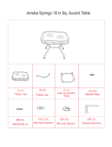
UNPACKING
When unpacking both boxes, check to make sure all the parts shown on the Parts Lists
on pages 52 through 61 are included. If any parts are missing or broken, please call
Harbor Freight Tools at the number shown on the cover of this manual as soon as possible.
TABLE SAW FEATURES
ASSEMBLY INSTRUCTIONS
FIGURE D
1. CAUTION! Always make sure the Power Switch (8E) of the Table Saw is in
its “OFF” position and the tool is unplugged from its electrical outlet prior to
assembling the tool, adding any accessories, or making adjustments to the tool.

SKU 93491 For technical questions, please call 1-800-444-3353. Page 14
To Assemble The Stand:
1. On a flat, dry, level surface lay out the following parts and hardware:
A. 4 Legs (4B).
B. 2 End Braces (6B).
C. 2 Side Braces (7B).
D. 2 Short Leg Braces (9B).
E. 2 Long Leg Braces (10B).
F. 24 Carriage Bolts (5B).
G. 4 Leveling Feet (1B).
H. 32 Washers (3B).
I. 32 Hex Nuts (2B).
2. Place a Short Leg Brace (9B) inside two of the Legs (4B), with the Legs wide end
up. (See Figure E.)
3. Align the two large holes in the Short Leg Brace (9B) and the two Legs (4B).
Insert the Carriage Bolts (5B). Add Washers (3B) and Hex Nuts (2B) and hand
tighten. Repeat this procedure for the remaining Short Leg Brace and two Legs.
(See Figure E.)
SIDE BRACE
(7B)
END BRACE
(6B)
LONG LEG BRACE
(10B)
SHORT LEG BRACE
(9B)
LEG
(4B)
LEVELING FOOT
(1B)
HEX NUT (2B)
WASHER (3B)
CARRIAGE BOLT
(5B)
HEX HEAD BOLT
(8B)
WASHER (3B)
HEX NUT (2B)
WASHER (3B)
FIGURE E
HEX NUT (2B)
WASHER (3B)
WASHER (3B)
HEX NUT (2B)

SKU 93491 For technical questions, please call 1-800-444-3353. Page 15
4. Attach a Long Leg Brace (10B) to two Legs (4B), using the Carriage Bolts (5B),
Washers (3B), and Hex Nuts (2B). Hand tighten only. Repeat this procedure for
the remaining Long Leg Brace and two Legs. (See Figure E.)
5. Use the same Steps to attach the End Braces (6B) and Side Braces (7B) to the
Legs (4B). (See Figure E.)
6. Tighten all the Hex Nuts (2B) using the Wrench (17-I) provided. (See Figure E.)
7. Place a Hex Nut (2B) and Washer (3B) on each Leveling Foot (1B). Insert the
threaded portion of the Leveling Feet upward through the bottom of each Leg
(4B). Cap with the remaining Washers (3B) and Hex Nuts (2B), but do not tighten
the top Hex Nut. (See Figure E.)
8. The location selected for the Table Saw must be level, dry, and well lighted. The
location must be capable of supporting the weight (approximately 310 pounds) of
the Table Saw and workpieces. There should also be room enough to allow
movement around the Saw with long pieces of woodstock.
9. Once located, set a carpenter’s level (not included) on the assembled Stand and
level the Stand from front to back and side to side. Adjust the Leveling Feet (1B)
with the Wrench (17-I). Then, tighten the top Hex Nut (2B) on the Leveling Feet.
(See Figure E.)
FIGURE F
ASSEMBLED STAND
To Attach The Saw Table To The Stand:
1. WARNING! Avoid injury. Do not lift the Saw Table without additional
help and a proper lifting device.

SKU 93491 For technical questions, please call 1-800-444-3353. Page 16
2. This procedure will require use of the following hardware:
A. 4 Hex Bolts (8B).
B. 8 Hex Nuts (2B).
C. 8 Washers (3B).
3. Check to make sure the Saw Blade (14-I) is fully retracted inside the Saw Table
(17H). Then, carefully set the Saw Table upside down on the floor surface,
(protect the Table top from being damaged). (See Figure G.)
4. Place the Stand upside down on the Saw Table Base (1G). Align the holes in the
Base with the holes in the End Braces (6B). (See Figure G.)
5. Place a Washer (3B) on a Hex Head Bolt (8B) and insert the Hex Head Bolt
upward through one of the previously aligned holes. Cap the Hex Head Bolt with
a Washer (3B) and Hex Nut (2B). Hand tighten only. (See Figure G.)
6. Repeat Step #5 for the three remaining holes. Then tighten all hardware with the
Wrench (17-I). NOTE: Leave the Table Saw sitting upside down.
(See Figure G.)
WASHER (3B)
HEX BOLT (8B)
HEX NUT (2B)
WASHER (3B)
STAND LEG (4B)
BASE (1G)
FIGURE G

SKU 93491 For technical questions, please call 1-800-444-3353. Page 17
To Attach The Saw Table Extensions:
1. This procedure will require use of the following hardware:
A. 8 Hex Bolts (8B).
B. 8 Hex Nuts (2B).
C. 16 Washers (3B).
2. With the Table Saw sitting upside down, align the Extension Tables (5H) with the
Saw Table (17H) with the bevel edges in front. (See Figure H.)
3. Place a Washer (3B) on each Hex Bolt (8B). Attach the Extension Tables (5H) to
the Saw Table (17H) by inserting the Hex Bolts from the direction of the Saw
Table. (See Figure H.)
4. Place the remaining Washers (3B) and Hex Nuts (2B) on the Hex Bolts (8B).
Lightly tighten the Hex Bolts with the Wrench (17-I). (See Figure H.)
5. With additional personnel and a proper lifting device, stand the Table Saw up-
right, using the center Saw Table (17H). Do not grasp the Extension Tables (5H).
(See Figure I.)
EXTENSION
TABLE
(5H)
EXTENSION
TABLE
(5H)
HEX
NUT
(2B)
WASHER
(3B)
HEX BOLT
(8B)
WOOD BLOCK
SIDE VIEW
FRONT VIEW
SAW TABLE EDGE
EXTENSION TABLE EDGE
TAP
HERE
TAP HERE
SAW TABLE EDGE
EXTENSION TABLE EDGE
FIGURE H

SKU 93491 For technical questions, please call 1-800-444-3353. Page 18
6. Stand at the front of the Table Saw and line up the front edges of the Saw Table
(17H) and Extension Tables (5H). (See Figure H.)
7. To align the Extension Tables (5H) with the Saw Table (17H) without damaging
the Table Saw, place a block of wood at the front of the Table Saw where the
Extension Table meets the Saw Table. Then, tap the block of wood with a
hammer. Check and repeat until the front edges are even. (See Figure H.)
8. Repeat this procedure for the rear edges of the Extension Tables (5H) Saw Table
(17H). When both the front and rear edges are even, tighten the Hex Bolts (8B)
with the Wrench (14-I). (See Figure H.)
To Attach The Rear Rail:
1. This procedure will require use of the following hardware:
A. 5 Square Head Bolts (10H).
B. 5 Hex Nuts (13H).
C. 5 Washers (12H).
2. At the back of the Saw Table (17H), place the Square Head Bolts (10H) in the
SQUARE
HEAD
BOLT
(10H)
WASHER
(12H)
HEX NUT
(13H)
REAR RAIL
(3H)
REAR RAIL
(3H)
SLOT
FOR
BOLT
EXTENSION
TABLE
(5H)
SQUARE
HEAD
BOLT
(10H)
HEX NUT
(13H)
WASHER
(12H)
2-1/2”
REAR RAIL
INSTALLED
FIGURE I

SKU 93491 For technical questions, please call 1-800-444-3353. Page 19
holes in the edge of the Saw Table (17H) and Extension Tables (5H) so the heads
of the Square Head Bolts (10H) extend outward 1/2 inch.
(See Figure I, previous page.)
3. Under the Saw Table (17H), loosely attach the Washers (12H) and Hex Nuts
(13H) onto the Square Head Bolts (10H). Slide the slot on the Rear Rail (3H)
over the Square Head Bolts. Adjust each Bolt to move the Rail closely to the
Saw Table. (See Figure I.)
4. Position the Rear Rail (3H) so that the right hand edge extends 2-1/2” beyond the
Extension Tables (5H). (See Figure I.)
5. Push the Rear Rail (3H) against the Saw Table (17H) and Extension Tables (5H)
and tighten each Hex Nut (13H) with the Wrench (17-I). If the Rear Rail does not
slide easily over the Square Head Bolts (10H), realign the Extension Tables.
(See Figure I.)
To Attach The Front Rail:
1. This procedure will require use of the following hardware:
A. 5 Square Head Bolts (10H).
B. 5 Hex Nuts (13H).
C. 5 Washers (12H).
D. Right and Left End Caps (8H, 9H) for the Front Rail (7H).
E. 2 Tapping Screws (1H) for the End Caps.
2. Insert the five Square Head Bolts (10H) into the Saw Table (17H) and Extension
Tables (5H) with the bolt heads extending out 1/2”. (See Figure J, next page.)
3. Under the Saw Table (17H) and Extension Tables (5H), loosely attach the
Washers (12H) and Hex Nuts (13H) onto the Square Head Bolts (10H).
(See Figure J.)
4. The back of the Front Rail (7H) has two slots. Slide the upper slot over the
Square Head Bolts (10H). (See Figure J.)
5. Align the Front Rail (7H) left to right -- match the 7-1/8” mark on the right Scale
(6H) to the right edge of the Saw Table (17H). (See Figure J.)
6. Snug the Front Rail (7H) against the Saw Table (17H) and Extension Tables (5H).
Then, finger-tighten each Hex Nut (13H) on the Saw Table and Extension Tables.
(See Figure J.)

SKU 93491 For technical questions, please call 1-800-444-3353. Page 20
SCALE
(6H)
FRONT RAIL
(7H)
SQUARE
HEAD
BOLT
(10H)
WASHER
(12H)
HEX NUT
(13H)
FRONT RAIL SLOT
HEX NUT
(13H)
FRONT RAIL (7H)
WASHER
(12H)
SCALE
(6H)
FRONT RAIL
(7H)
7-1/8” MARK (RIGHT SCALE)
EXTENSION
TABLE
(5H)
SAW TABLE
(17H)
TOP VIEW
FIGURE J
To Align The Rip Fence And Front Rail:
1. NOTE: The Rip Fence Scale Indicator (20C) is installed on the right side of the
Rip Fence (10C), but can be removed and reinstalled on the left side if needed. If
a cutting operation requires placing the Rip Fence on the left side of the Saw
Blade (14-I), and relocating the Rip Fence Scale Indicator is necessary, simply
unscrew the Indicator and align and reattach it on the left side.
(See Assy. Diagram C.)
2. Hook the back of the Rip Fence (10C) over the Rear Rail (3H). Lower the front of
the Rip Fence into the groove on the Front Rail (7H).
(See Figure K, next page.)
/