Chicago Electric 96697 Set Up And Operating Instructions Manual
- Category
- Power tools
- Type
- Set Up And Operating Instructions Manual

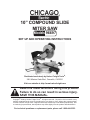
10” COMPOUND SLIDE
MITER SAW
Models
96697
SET UP AND OPERATING INSTRUCTIONS
Distributed exclusively by Harbor Freight Tools
®
.
3491 Mission Oaks Blvd., Camarillo, CA 93011
Visit our website at: http://www.harborfreight.com
Read this material before using this product.
Failure to do so can result in serious injury.
SAVE THIS MANUAL.
Copyright
©
2008 by Harbor Freight Tools
®
. All rights reserved. No portion of this manual or any
artwork contained herein may be reproduced in any shape or form without the express written
consent of Harbor Freight Tools. Diagrams within this manual may not be drawn proportionally. Due
to continuing improvements, actual product may differ slightly from the product described herein.
For technical questions or replacement parts, please call 1-800-444-3353.

Page 2SKU 96697 For technical questions, please call 1-800-444-3353.
SAVE THIS MANUAL
Keep this manual for the safety
warnings and precautions, assembly,
operating, inspection, maintenance and
cleaning procedures. Write the product’s
serial number in the back of the manual
near the assembly diagram (or month
and year of purchase if product has no
number). Keep this manual and the
receipt in a safe and dry place for future
reference.
IMPORTANT SAFETY
INFORMATION
In this manual, on the labeling,
and all other information
provided with this product:
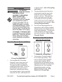
This is the safety alert
symbol. It is used to alert
you to potential personal
injury hazards. Obey all
safety messages that
follow this symbol to avoid
possible injury or death.
DANGER indicates
a hazardous
situation which, if not
avoided, will result in death or
serious injury.
WARNING
indicates a
hazardous situation which, if
not avoided, could result in
death or serious injury.
CAUTION, used
with the safety
alert symbol, indicates a
hazardous situation which, if
not avoided, could result in
minor or moderate injury.
NOTICE is used to
address practices
not related to personal injury.
CAUTION, without
the safety alert
symbol, is used to address
practices not related to
personal injury.
General Safety Rules
WARNING! Read all instructions
Failure to follow all instructions
listed below may result in
electric shock, re, and/or
serious injury. The term “power
tool” in all of the warnings listed
below refers to your line-operated
(corded) power tool or battery-
operated (cordless) power tool.
SAVE THESE INSTRUCTIONS
Work area safety1.
Keep work area clean and well a.
lit. Cluttered or dark areas invite
accidents.
Do not operate power tools in b.
explosive atmospheres, such as in
gases or dust. Power tools create
sparks which may ignite the dust or
fumes.
Keep children and bystanders c.
away while operating a power
tool. Distractions can cause you
to lose control.
DANGER
WARNING
CAUTION
NOTICE
CAUTION

Page 3SKU 96697 For technical questions, please call 1-800-444-3353.
Electrical safety2.
Power tool plugs must match the a.
outlet. Never modify the plug in
any way. Do not use any adapter
plugs with grounded power tools.
Unmodied plugs and matching
outlets will reduce risk of electric
shock.
Avoid body contact with grounded b.
surfaces such as pipes, radiators,
ranges and refrigerators. There is
an increased risk of electric shock if
your body is grounded.
Do not expose power tools to rain c.
or wet conditions. Water entering
a power tool will increase the risk
of electric shock.
Do not abuse the cord. Never use d.
the cord for carrying, pulling or
unplugging the power tool. Keep
cord away from heat, oil, sharp
edges or moving parts. Damaged
or entangled cords increase the
risk of electric shock.
When operating a power tool e.
outdoors, use an extension cord
suitable for outdoor use. Use of
a cord suitable for outdoor use
reduces the risk of electric shock.
Personal safety3.
Stay alert, watch what you are a.
doing and use common sense
when operating a power tool. Do
not use a power tool while you are
alcohol or medication. A moment
of inattention while operating power
tools may result in serious personal
injury.
Use safety equipment. Always b.
wear ANSI-approved eye
protection and dust mask/
respirator when using this
product. Safety equipment such
as non-skid safety shoes, hard
hat, or hearing protection used for
appropriate conditions will reduce
personal injuries.
Avoid accidental starting. Ensure c.
the switch is in the off-position
before plugging in. Carrying power
tools with your nger on the switch
or plugging in power tools that have
the switch on invites accidents.
Remove any adjusting key or wrench d.
before turning the power tool on. A
wrench or a key left attached to a
rotating part of the power tool may
result in personal injury.
Do not overreach. Keep proper e.
footing and balance at all times.
This enables better control of the
power tool in unexpected situations.
Dress properly. Do not wear loose f.
clothing or jewelry. Keep your hair,
clothing and gloves away from
moving parts. Loose clothes, jewelry
or long hair can be caught in moving
parts.
A device is provided for the g.
connection of dust extraction and
collection facilities, ensure this is
connected and properly used. Use
of this devices can reduce dust-
related hazards.
Power tool use and care4.
Do not force the power tool. Use a.
the correct power tool for your
application. The correct power tool
will do the job better and safer at the
rate for which it was designed.
Do not use the power tool if the b.
switch does not turn it on and
off. Any power tool that cannot

Page 4SKU 96697 For technical questions, please call 1-800-444-3353.
be controlled with the switch is
dangerous and must be repaired.
Disconnect the plug from the c.
power source and/or the battery
pack from the power tool before
making any adjustments,
changing accessories, or storing
power tools. Such preventive
safety measures reduce the
risk of starting the power tool
accidentally.
Store idle power tools out of d.
the reach of children and do not
allow persons unfamiliar with the
power tool or these instructions
to operate the power tool. Power
tools are dangerous in the hands
of untrained users.
Maintain power tools. Check for e.
misalignment or binding of moving
parts, breakage of parts and any
other condition that may affect the
power tool’s operation. If damaged,
have the power tool repaired before
use. Many accidents are caused by
poorly maintained power tools.
Keep cutting tools sharp and clean. f.
Properly maintained cutting tools
with sharp cutting edges are less
likely to bind and are easier to
control.
Use the power tool and accessories g.
in accordance with these instructions
and in the manner intended for the
particular type of power tool, taking
into account the working conditions
and the work to be performed. Use
of the power tool for operations
different from those intended could
result in a hazardous situation.
Service5.
Have your power tool serviced by a.
identical replacement parts. This will
ensure that the safety of the power
tool is maintained.
Specic Safety Rules
Keep hands out of path of saw blade.1.
Do not operate saw without guards in 2.
place.
Do not perform any operation 3.
freehand.
Never reach around saw blade.4.
Turn off tool and wait for saw blade 5.
to stop before moving workpiece or
changing settings.
Unplug tool before changing blade or 6.
servicing.
To reduce the risk of injury, pull 7.
carriage to full rear position after
each crosscut operation.
Do not expose to rain or use in damp 8.
locations.
Only use 10” maximum diameter 9.
blade rated at 5,000 RPM or greater.
Maintain labels and nameplates on 10.
the tool. These carry important safety
information. If unreadable or missing,
contact Harbor Freight Tools for a
replacement.
Avoid unintentional starting. Prepare 11.
to begin work before turning on the
tool.
Do not walk away from this tool until 12.
it has come to a complete stop.

Page 5SKU 96697 For technical questions, please call 1-800-444-3353.
Moving parts can grab any surface
and cause damage or injury.
Do not leave the tool unattended 13.
when it is plugged into an electrical
outlet. Turn off the tool, and unplug
it from its electrical outlet before
leaving.
Use the provided clamps or other 14.
practical ways to secure and support
the work piece to the Table. Holding
the work by hand or against your
body is unstable and may lead to loss
of control.
This product is not a toy. Keep it out 15.
of reach of children.
People with pacemakers should 16.
consult their physician(s) before
proximity to heart pacemaker could
cause pacemaker interference or
pacemaker failure. In addition,
people with pacemakers should:
on.
avoid electrical shock.
grounded. Ground Fault Circuit
Interrupter (GFCI) should also be
implemented – it prevents sustained
electrical shock.
Some dust created by power 17.
sanding, sawing, grinding, drilling,
and other construction activities,
contains chemicals known [to the
State of California] to cause cancer,
birth defects or other reproductive
harm. Some examples of these
chemicals are:
cement or other masonry products
chemically treated lumber
Your risk from these exposures
varies, depending on how often you
do this type of work. To reduce your
exposure to these chemicals: work in
a well ventilated area, and work with
those dust masks that are specially
particles. (California Health & Safety
Code § 25249.5, et seq.)
The warnings, precautions, 18.
and instructions discussed in
this instruction manual cannot
cover all possible conditions and
situations that may occur. It must
be understood by the operator that
common sense and caution are
factors which cannot be built into this
product, but must be supplied by the
operator.
SAVE THESE
INSTRUCTIONS.

Page 6SKU 96697 For technical questions, please call 1-800-444-3353.
GROUNDING
TO PREVENT
ELECTRIC SHOCK
AND DEATH FROM
INCORRECT GROUNDING
WIRE CONNECTION:
Check with a qualied
electrician if you are in doubt
as to whether the outlet is
properly grounded. Do not
modify the power cord plug
provided with the tool. Never
remove the grounding prong
from the plug. Do not use the
tool if the power cord or plug
is damaged. If damaged, have
it repaired by a service facility
before use. If the plug will not
t the outlet, have a proper
outlet installed by a qualied
electrician.
Grounded Tools: Tools with Three
Prong Plugs
3-Prong Plug and Outlet
1. Tools marked with “Grounding
and three prong grounding plug.
The plug must be connected to a
properly grounded outlet. If the tool
should electrically malfunction or
break down, grounding provides a
low resistance path to carry electricity
away from the user, reducing the risk
of electric shock. (See 3-Prong Plug
and Outlet.)
The grounding prong in the plug is 2.
connected through the green wire
inside the cord to the grounding
system in the tool. The green wire
in the cord must be the only wire
connected to the tool’s grounding
system and must never be attached
to an electrically “live” terminal. (See
3-Prong Plug and Outlet.)
The tool must be plugged into an 3.
appropriate outlet, properly installed
and grounded in accordance with all
codes and ordinances. The plug and
outlet should look like those in the
preceding illustration. (See 3-Prong
Plug and Outlet.)
Double Insulated Tools: Tools
with Two Prong Plugs
Outlets for 2-Prong Plug
1. Tools marked “Double Insulated”
have a special double insulation
applicable standards of Underwriters
Standard Association, and the
National Electrical Code. (See
Outlets for 2-Prong Plug.)
WARNING

Page 7SKU 96697 For technical questions, please call 1-800-444-3353.
Double insulated tools may be used 2.
in either of the 120 volt outlets shown
in the preceding illustration. (See
Outlets for 2-Prong Plug.)
Extension Cords
Grounded1.
extension cord. Double Insulated
tools can use either a two or three
wire extension cord.
As the distance from the supply 2.
outlet increases, you must use a
heavier gauge extension cord. Using
sized wire causes a serious drop in
voltage, resulting in loss of power and
possible tool damage.
(See Table A.)
The smaller the gauge number of the 3.
wire, the greater the capacity of the
cord. For example, a 14 gauge cord
can carry a higher current than a 16
gauge cord. (See Table A.)
When using more than one extension 4.
cord to make up the total length,
make sure each cord contains at
(See Table A.)
If you are using one extension cord 5.
for more than one tool, add the
nameplate amperes and use the sum
cord size. (See Table A.)
If you are using an extension cord 6.
outdoors, make sure it is marked with
indicate it is acceptable for outdoor
use.
Make sure the extension cord is 7.
properly wired and in good electrical
condition. Always replace a damaged
extension cord or have it repaired by
Protect the extension cords from 8.
sharp objects, excessive heat, and
damp or wet areas.
RECOMMENDED MINIMUM WIRE
GAUGE FOR EXTENSION CORDS*
(120/240 VOLT)
NAMEPLATE
AMPERES
(at full load)
EXTENSION CORD
LENGTH
25’
50’
75’
100’
150’
0 – 2.0 18 18 18 18 16
2.1 – 3.4 18 18 18 16 14
3.5 – 5.0 18 18 16 14 12
5.1 – 7.0 18 16 14 12 12
7.1 – 12.0 18 14 12 10 -
12.1 – 16.0 14 12 10 - -
16.1 – 20.0 12 10 - - -
TABLE A
* Based on limiting the line
voltage drop to ve volts at
150% of the rated amperes.
Symbology
Double Insulated
Canadian Standards Association
V~
Volts Alternating Current
A
Amperes
n
0
xxxx/min.
(RPM)

Page 8SKU 96697 For technical questions, please call 1-800-444-3353.
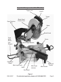
Important Components of the Miter Saw
Dust Collection
Bag
Hold Down
Clamp
Blade Guard
Center Cover
Handle
Trigger
Blade
Blade Guard
Bevel Angle Indicator
Fence
Handle
Miter Handle
Miter Angle
Indicator
Table
Base
Miter Angle Scale
Work
piece
Exten-
sion
Support
Kerf Board
Figure 1

Page 9SKU 96697 For technical questions, please call 1-800-444-3353.
Bevel Angle Controls and Features on the Rear of the Miter Saw
Trigger
Dust Outlet
Depth Stop Screw 102)
Release
Button
Support Foot
Bevel Angle Indicator
Slides (54 & 55)
Figure 2

Page 10SKU 96697 For technical questions, please call 1-800-444-3353.
SPECIFICATIONS
Motor
120 V~ / 60 Hz / 11.25 A
n
0
4600/min
1-¾ HP
Arbor Diameter 5/8”
Blade Type General Purpose Carbide Tipped
Blade Diameter 10”
Cutting
Capacity
At 90°: 2.95” Deep x 11.8” Wide
At 45°: 1.57” Deep x 8.26” Wide
Positive Table
Stops
0°, 15°, 22.5°, 30° and 45° both
Positive Bevel
Stops
Blade Tilt
Range
0° - 45° compound
Scale 1° per scale mark
E105017
UNPACKING
When unpacking, check to make sure
that the item is intact and undamaged. If
any parts are missing or broken, please
call Harbor Freight Tools at the number
shown on the cover of this manual as soon
as possible.
List of contents
Description Qty
Compound Sliding Miter Saw 1
Carbide Tipped Blade 1
Table Extensions 2
Dust Collection Bag 1
Wrench 1
INITIAL SET UP
INSTRUCTIONS
Read the ENTIRE IMPORTANT
SAFETY INFORMATION section
at the beginning of this manual
including all text under
subheadings therein before set
up or use of this product.
TO PREVENT
SERIOUS INJURY
FROM ACCIDENTAL
OPERATION:
Turn the Power Switch of the
tool to its “OFF” position and
unplug the tool from its
electrical outlet before
assembling or making any
adjustments to the tool.
Note: For additional information regarding
the parts listed in the following pages,
refer to the Assembly Diagram near
the end of this manual.
Assembly
Attaching the Extension Supports
Insert the ends of the Extension 1.
Supports into the holes in the sides
of the Base. Tighten the Wing Screws
to hold the Extensions in place. The
upper edge of the Extensions will be
level with the surface of the saw. This
provides a wider base for the work
material to rest on.
Attaching the Dust Collection Bag
The Dust Collection Bag slips over 2.
the Dust Outlet behind the Blade
Housing Assembly. Sawdust created
by cutting is captured in the bag.
Mounting the Saw
The Miter Saw must be mounted on
a support before use. This may be
a commercially available support or
home made saw table. There are
bolt holes provided in each of the
WARNING
REV 08f

Page 11SKU 96697 For technical questions, please call 1-800-444-3353.
four legs of the base. These should
included) to your saw stand or saw
table (not included). This will help
prevent tipping or movement of the
saw, preventing injury. Also, the use
of a saw table will make it easier to
make more accurate cuts.
OPERATING INSTRUCTIONS
Read the ENTIRE IMPORTANT
SAFETY INFORMATION section
at the beginning of this manual
including all text under
subheadings therein before set
up or use of this product.
TO PREVENT
SERIOUS INJURY
FROM ACCIDENTAL
OPERATION:
Unplug power cord from
power source before making
any adjustments to this tool.
Work Piece and Work Area Set Up
Designate a work area that is clean 1.
and well-lit. The work area must not
allow access by children or pets to
prevent injury and distraction.
Route the power cord along a safe 2.
route to reach the work area without
creating a tripping hazard or exposing
the power cord to possible damage.
The power cord must reach the work
area with enough extra length to
allow free movement while working.
Use a saw table, saw stand or other 3.
means to support the work piece.
The Miter Saw must be mounted in
such a way that the surface is level to
the ground, and supports used must
provide a surface on the same level
as the saw table. If the work surface
and any work materials supports
are not level, and on the same level,
unwanted bevel angles will appear in
the cuts resulting in poor joinery.
Work pieces may be secured to 4.
the saw table using the Hold Down
Clamp or other clamping devices (not
included). Securing the work piece
will provide safety by preventing
kick back and by removing the need
to hold work pieces near the blade
by hand. Clamping the work piece
will also improve cutting accuracy
by preventing the work piece from
moving during the cutting operation.
When using this saw, work pieces 5.
both left and right of saw for extended
work pieces.
General Operating Instructions
When the Handle is lowered, the 1.
Blade Guard raises automatically.
When the Handle is raised the Blade
Guard returns to its safety position.
Keep hands clear of the Blade
when the Handle is lowered. Never
interfere with the proper movement of
the Blade Guard.
There are locking mechanisms for the 2.
miter angle and the Slides. Unlock
the Table to set the miter angle,
then re-lock it before making the
cut. Unlock the Slide using the Slide
cut if the work material is too wide to
“chop”.
To rotate the Table, press down the 3.
WARNING

Page 12SKU 96697 For technical questions, please call 1-800-444-3353.
to the desired angle, then release
machined into the Base of the tool
which will lock the Table into several
often used miter angles. These
angles are 0º (centered), 15º, 22.5º,
30º and 45º both left and right cut.
On wider pieces, you will have to 4.
slide the blade while making the cut.
To unlock the Slide, loosen the Slide
saw.
To make a bevel cut, release the 5.
assembly to the desired bevel angle,
then lock the blade assembly in place
bevel cuts is discussed in more detail
later in this manual.
This saw is provided with a Kerf 6.
Board. The Kerf Board helps to
prevent tear-out on the bottom side
of the work material. The Kerf Board
is factory adjusted prior to shipment
of this tool so the blade does not
contact the Kerf Board during normal
operation, including bevel cuts.
Adjustment of the Kerf Board and
discussed later in this booklet.
Before starting work, check the 7.
accuracy of the Guide Fence, miter
angle and bevel angle. Instructions
for checking and adjusting these
angles are discussed later in this
booklet.
It is very important that the work 8.
material be properly supported before
making a cut. The material must be
level on the Table. The material must
be supported on both ends. Using the
Work Piece Extension Supports is
discussed in the next section.
Using the Work Piece Extension
Supports
The Work Piece Extension Supports 1.
are inserted into each side of the
Table, and locked in place using the
Wing Screws.
When properly installed, the upper 2.
face of the Work Piece Extension
Supports are level with the Table, and
provide a wider support surface for
the work piece.
Always support the work piece to be 3.
level with the table, and so that after
the cut is made the cut off pieces
will not fall. You may need to use
saw horses or other supports (not
included) to support the work piece.
If the work piece is not level, you will 4.
make an unintentional bevel cut in
the material. If the work piece is not
supported, it will bind the blade and
may cause the material to kick back,
potentially causing injury.
Adjusting the Miter Angle
A miter cut is one that is at an angle 1.
across the horizontal surface of the
material. You will commonly make
45º miter cuts to join two pieces in a
right angle corner. A 30º cut is often
used for a scarf joint or to make a
chamfered end.
To make a miter cut, loosen 2.
turning it approximately 1/4 turn
counterclockwise. Move the Table to
the desired angle. The Miter Angle
Indicator will indicate the selected
REV 09e

Page 13SKU 96697 For technical questions, please call 1-800-444-3353.
angle. The table will lock into place
at often used miter angles, including
22.5º, 30º, 45º, and 90º on both left
and right sides.
With the Table adjusted to the desired 3.
against the Fence, secure it with the
Hold Down Clamp and make the cut.
Adjusting the Bevel Angle
A bevel cut is one that is at an angle 1.
to the vertical plane of the material.
Bevel cuts can be used to miter 2.
relatively wide and thin material.
Bevel cuts can be used in
combination with a miter cut to form
a compound angle. Compound angle
cuts are often used in crown, picture
frames and similar trim materials.
To set the bevel angle, loosen the 3.
the saw. (See Figure 2.) To do this,
the Handle 1/2 turn counterclockwise.
Move the blade assembly left to the
desired angle. You can read the
angle on the Bevel Angle Indicator.
tight.
Make a sample cut in a piece of scrap 4.
and check to be sure the bevel angle
is correct. If it is not, correct the angle
before cutting your work material.
Using the Depth Stop
1.
rabbet cut which does not cut through
the work piece, you can use the
Depth Stop Screw to control the
depth of the cut. (See Figure 2.)
To limit blade assembly travel, turn 2.
the Depth Stop Screw clockwise.
The further you screw down the
Depth Stop Screw, the shallower the
cut will be.
After the desired cut has been 3.
made, return the Depth Stop Screw
to its open position by turning it
counterclockwise.
Making a Cut
Observe all safety and planning items 1.
discussed in this booklet. Detailed
instructions on each of the following
steps are discussed in this booklet.
Do not make any cuts until you have
read this entire booklet and are
familiar with the operation of this tool.
2.
blade assembly to come up. Check
at the desired miter angle. Check
to be sure the slide lock is released
to allow the blade assembly to slide
freely.
Blow any sawdust or debris away 3.
from the Fence. Place the work
material against the Fence.
Make any necessary miter or bevel 4.
adjustments.
Align the marked location of the cut 5.
on the work material with the saw
blade. Be aware that the Saw Blade
will remove material from the cut
the “kerf”. To prevent your work piece
from being cut too short, align the
edge of the blade with your measured

Page 14SKU 96697 For technical questions, please call 1-800-444-3353.
mark, keeping the kerf on the waste
side of the cut.
Hold the work material in place using 6.
the Hold Down Vise. Ensure that the
work material is level and supported
securely, using saw horses or
supports if necessary.
Grip the Saw Handle, press the 7.
Trigger to start the Blade turning.
Pressing down lightly, move the 8.
Blade smoothly across the work
material to cut it. With narrow
material, you can press straight down
“chopping” the material. With wider
material you must move the Blade
across the material to cut it. Do not
bear down on the material, use light
downward pressure. If the material
binds the blade, release the trigger.
Keep your hands away from the
Blade.
When the cut is completed, raise the 9.
blade assembly, wait for the Blade to
stop turning, release the Hold Down
Vise and remove the work material
from the saw.

Page 15SKU 96697 For technical questions, please call 1-800-444-3353.
MAINTENANCE AND
SERVICING
Procedures not specically
explained in this manual
must be performed only by a
qualied technician.
TO PREVENT
SERIOUS INJURY
FROM ACCIDENTAL
OPERATION:
Turn the Power Switch of the
tool to its “OFF” position and
unplug the tool from its
electrical outlet before
performing any inspection,
maintenance, or cleaning
procedures.
TO PREVENT SERIOUS
INJURY FROM TOOL
FAILURE:
Do not use damaged
equipment. If abnormal noise
or vibration occurs, have the
problem corrected before
further use.
Cleaning, Maintenance, and
Lubrication
BEFORE EACH USE,1. inspect the
general condition of the tool. Check
for loose screws, misalignment or
binding of moving parts, cracked or
broken parts, damaged electrical
wiring, and any other condition that
may affect its safe operation.
AFTER USE,2. clean external surfaces
of the tool with clean, moist cloth.
To prevent accidents, turn off the
tool and disconnect its power supply
after use. Clean, then store the tool
indoors out of children’s reach.
If the blade has become dirty, use a 3.
blade cleaner (not included) to clean
it. Dirty blades will bind more easily,
and will more often overheat and
burn the wood as it cuts. Overheated
blades dull more easily.
If the Blade has become dull, replace 4.
it. Dull blades will cause increased
tear-out and ragged edges on the
cuts.
Occasionally clean the Slides, 5.
rotating Table components and other
lubricant (not included) which will not
attract dust.
6. WARNING! If the supply cord of
this power tool is damaged, it must
be replaced only by a qualied
service technician.
Replacing the Blade
TO REDUCE RISK
OF SERIOUS
INJURY:
Return guard to original
position and secure in place
after replacing blade.
Unplug the tool from its power 1.
source.
2.
Pin.
WARNING
WARNING

Page 16SKU 96697 For technical questions, please call 1-800-444-3353.
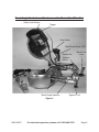
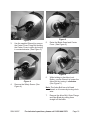
Figure 3
3. Use the supplied Wrench to remove
the Center Cover Fixing Bolt holding
the Center Cover in place by turning
it counterclockwise. (See Figure 3.)
Figure 4
4. Remove the Safety Screw. (See
Figure 4.)
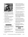
Figure 5
5. Raise the Blade Guard and Center
Cover. (See Figure 5.)
Figure 6
6.
Button, use the Wrench to loosen the
Arbor Bolt by turning it clockwise.
(See Figure 6.)
Note: The Arbor Bolt has a left hand
thread, so it loosens by turning clock-
wise.
Remove the Arbor Bolt, Outer Flange 7.
and Saw Blade by pulling them
straight off the Arbor.

Page 17SKU 96697 For technical questions, please call 1-800-444-3353.
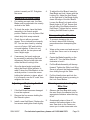
Figure 7
8. Reinstall a new Blade on the Arbor.
(See Figure 7.) Be sure to match the
direction marked on the new blade
with the direction marked on the saw
Blade Housing.
Replace the Outer Flange and Arbor 9.
Bolt. Tighten the Arbor Bolt securely
using the Wrench by turning it
counterclockwise.
Rotate the Center Cover back into 10.
place and tighten the Center Cover
Fixing Bolt using the Wrench by
turning it clockwise.
11.
Adjusting the Fence
The Fence holds the work piece in a 1.
the blade assembly are adjusted in a
miter or bevel angle.
To make accurate cuts, the Fence 2.
must be perpendicular (at a 90º
angle) to the Saw Blade.
Before beginning work, make a test 3.
cut on scrap material with the Table
set at 90º.
Check the cut with an accurate 4.
pieces, hold the cut ends together,
and hold a good straight edge along
the side of the pieces.
If either test reveals that the cut is not 5.
a true 90º angle, you must adjust the
Fence before beginning work.
6.
tool.
7.
8.
the table with one edge along the
blade and the other along the Fence.
Any inaccuracy should be visible.
surface of the blade, not the teeth, for
an accurate reading.
The Fence is held in place with 9.
slightly, and gently tap the Fence into
position using a soft mallet. Retighten
the bolts and make another test cut.
Repeat the process until the Fence is
adjusted accurately.
Once the Fence is accurately 10.
place. Recheck one last time, then
proceed to work.
Adjusting the Miter Table
Indicator
After you have checked or adjusted 1.
the fence to be sure it is at 90º to the
Blade, you must check the accuracy
of the Miter Table Angle Indicator.
2.
Indicator in place. Rotate it until the

Page 18SKU 96697 For technical questions, please call 1-800-444-3353.
pointer is exactly on 90º. Retighten
the screw.
Adjusting the Bevel Angle
For making accurate cuts, the Saw 1.
Blade must be adjusted to be exactly
vertical to the Table.
To check the angle, have the blade 2.
assembly in its normal upright
sided, fairly thick scrap material.
Check the cut with an accurate 3.
90º. You can also check by rotating
one cut-off piece 180º and hold the
cut ends together. If the cut is not
exactly vertical, the two pieces will
form a slight angle.
If necessary, the bevel angle can 4.
be corrected by adjusting the Bevel
Adjustment Screw on the right side
Once the bevel angle is adjusted, 5.
adjust the Bevel Angle Indicator to
read 0º when the Saw Blade is in the
holding the Indicator in place, adjust
it to be exactly over the 0º mark, then
retighten the screw.
Adjusting or Replacing the Kerf
Board
If the Kerf Board becomes damaged 1.
it must be replaced.
Remove the four screws holding the 2.
Kerf Board in place.
Install a new Kerf Board. Replace the 3.
four screws and tighten them slightly.
To adjust the Kerf Board, lower the 4.
Saw Blade and lock it down with the
so the right side of the Blade slightly
clears the edge of the Kerf Board.
Bevel Angle at 45º left. Ensure that
the left side of the Blade clears the
Kerf Board. Tighten the four screws
holding the Kerf Board in place.
Transporting the Miter Saw
To prevent damaging this tool 1.
in transit, observe the following
precautions when transporting the
tool.
Wrap up the power cord and secure it 2.
to the saw. Use a cord or tie wrap to
do this.
Center the Blade Assembly on the 3.
table at 0º. Turn the Miter Handle
clockwise to lock it.
Pull the Blade Assembly all the way 4.
Screw to prevent the blade assembly
from sliding through the Table.
Pull the Handle down and lock the 5.
Blade Assembly down by pressing in
Cleaning and Lubricating the
Miter Saw
Observe the Dust Bag while using 1.
the saw. Empty the sawdust into an
appropriate container when the bag
is full.
Occasionally wipe or blow off 2.
sawdust that accumulates on the
saw. Saw dust on the Fence can
cause you to make inaccurate cuts.

Page 19SKU 96697 For technical questions, please call 1-800-444-3353.
Keep the Slides free of sawdust. 3.
Use a dry lubricant or wax on the
slides. Do not use an oil or grease
lubricant, as this will attract dust.
Occasionally lubricate the pivot point 4.
of the Table as well as other moving
parts with a dry lubricant.
Troubleshooting
Problem Possible Causes Likely Solutions
Tool will not start No power at outlet.1.
Cord not connected.2.
Check power at outlet.1.
Check that cord is plugged in.2.
Tool operates
sporadically or at
low power
1.
extension cords.
Worn or cracked Carbon 2.
Brushes.
Check power supply and power cords. 1.
Check Carbon Brushes. Replace if damaged 2.
or worn.
Wood burns at
ends when cut
Dirty Blade. 1.
Material is binding.2.
Clean Blade using blade cleaner or mineral 1.
spirits.
Check position of work material on Table. 2.
and supported on ends.
Material frays or
chips out.
Finished side is down 1.
Blade is chipped or dull. 2.
Blade is inappropriate for 3.
material.
Material is unsupported.4.
1.
facing you. Bottom and back side are prone
to chip out.
Check for damaged teeth. Sharpen or 2.
replace blade.
Check blade manufacturer’s 3.
recommendations for material being cut. For
cross cutting hard wood and for precision
cuts use a thin kerf blade with 60 or more
teeth.
4.
as 1/4” plywood, underneath or behind the
material to support the edges of the material
as it is being cut.
Blade binds
slowing or
stopping saw.
Material is misaligned on 1.
the saw or ends are not
supported.
Material is wet, contaminated 2.
or inappropriate blade is
being used.
1.
the fence and supported on both ends.
Check condition of material and check 2.
compatibility of blade to material.
Follow all safety precautions whenever diagnosing or servicing the tool.
Disconnect power supply before service.

Page 20SKU 96697 For technical questions, please call 1-800-444-3353.
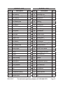
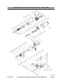
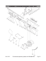
PARTS LIST
Part# Description Qty
1 1
2 Ball bearing 1
3 Armature assembly 1
4 Ball bearing 1
5 Fan guide 1
6 Pan head screw 2
7 Spring washer 2
8 Flat washer 2
9 Stator assembly 1
10 Power cord 1
11 Cord guard 1
12 Screw 2
13 Cord clips 2
14 Safety lever 1
15 1
16 Compressor spring 1
17 Flat washer 4
18 Spring washer 4
19 Pan head screw 4
20 Brush holder cap 2
21 Brush holder 2
22 Brush holder 2
23 Switch 1
24 Trigger 1
25 Motor housing 1
27 Gear housing 1
28 Helical gear 1
29 Bearing box 1
30 Flat washer 2
31 Spring washer 2
32 Pan head screw 2
33 Key 1
34 Arbor 1
35 Compressor spring 1
36 Pan head screw 4
37 Handle cover 1
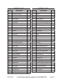
PARTS LIST
Part# Description Qty
38 Bearing 1
39 Retaining ring 1
40 Blade Housing Assembly 1
41 Rubber nut 1
42 Hex bolt 1
43 Bearing 1
44 Dust Outlet 1
45 Flat washer 2
46 Saw blade 1
47 Outer Flange 1
48 Flat washer 1
49 Arbor bolt 1
50 Center cover 1
51 Torsion spring 1
52 Blade guard 1
53 Blade Guard Center cover 1
54 Flat washer 1
55 Center Cover Fixing Bolt 1
56 Spindle Sleeve 1
57 Triangle screw 1
58 1
59 Screw 1
60 1
61 Hex head bolt 2
62 Screw 1
63 Sleeve 1
64 Flange 1
65 Compressor spring 1
66 1
67 Hex head bolt 2
68 Spring washer 2
69 Flat washer 2
70 Bracket 1
71 Depth Stop bolt 1
72 Stopper plate 1
73 Nut 1
REV 08f
Page is loading ...
Page is loading ...
Page is loading ...
Page is loading ...
-
 1
1
-
 2
2
-
 3
3
-
 4
4
-
 5
5
-
 6
6
-
 7
7
-
 8
8
-
 9
9
-
 10
10
-
 11
11
-
 12
12
-
 13
13
-
 14
14
-
 15
15
-
 16
16
-
 17
17
-
 18
18
-
 19
19
-
 20
20
-
 21
21
-
 22
22
-
 23
23
-
 24
24


Chicago Electric 96697 Set Up And Operating Instructions Manual
- Category
- Power tools
- Type
- Set Up And Operating Instructions Manual
Ask a question and I''ll find the answer in the document
Finding information in a document is now easier with AI
Related papers
-
Chicago Electric 91935 Assembly And Operating Instructions Manual
-
-
-
-
-
-
-
-
-
Other documents
-
Commax TP-NR Owner's manual
-
 Ironton 10in. Compound Sliding Miter Saw Owner's manual
-
 Ironton 10in. Compound Sliding Miter Saw Owner's manual
-
Harbor Freight Tools 96067 User manual
-
Craftsman 12" Single Bevel Sliding Compound Miter Saw (21239) Manufacturer's Warranty
-
-
-
-
-
Drill Master 3733 User manual

