Page is loading ...

REMOVAL, OVERHAUL & INSTALLATION
2001 Chevrolet Camaro
2001 ENGINE PERFORMANCE
Removal, Overhaul & Installation - Cars
MODEL IDENTIFICATION
Vehicle model is identified by fourth character of Vehicle
Identification Number (VIN). VIN is stamped on metal pad on top of
left end of instrument panel, near windshield. See
MODEL IDENTIFICATION table.
MODEL IDENTIFICATION
Body Code (1) Model
"C" .................................................... Park Avenue
"E" ....................................................... Eldorado
"F" .............................................. Camaro & Firebird
"H" ........................................... Bonneville & LeSabre
"G" ......................................................... Aurora
"J" ........................ Cavalier, Sunfire & Saturn ("L" Series)
"K" .............................................. DeVille & Seville
"M" .......................................................... Metro
"N" ....................................... Alero, Grand Am & Malibu
"S" .......................................................... Prizm
"V" ......................................................... Catera
"W" ................. Century, Grand Prix, Impala, Intrigue, Lumina,
Monte Carlo & Regal
"Y" ....................................................... Corvette
"Z" ............................................ Saturn ("S" Series)
(1) - Vehicle body code is fourth character of VIN.
INTRODUCTION
CAUTION: When battery and some PCM input devices are disconnected,
vehicle computer and memory systems may lose memory data.
Driveability problems may exist until computer systems have
completed a relearn cycle. See COMPUTER RELEARN PROCEDURES
article in GENERAL INFORMATION before disconnecting battery.
This article covers removal, overhaul and installation
procedures (when given by manufacturer). If component removal and
installation is primarily an unbolt and bolt-on procedure, only a
torque specification may be supplied.
AIR INDUCTION SYSTEMS
SUPERCHARGER
NOTE: Servicing of supercharger unit is limited to replacement
only.
Removal (3.8L - VIN 1)
1) Relieve fuel pressure. See
FUEL SYSTEM PRESSURE RELEASE (GASOLINE). Disconnect negative battery
cable. Remove accessory drive belt from supercharger pulley.
2) Remove fuel injector sight shield. Disconnect fuel lines

from fuel rail. Disconnect vacuum hoses. Disconnect injector harness
connectors. Disconnect harness connectors from front of supercharger.
Remove fuel rail bolts. Remove fuel rail and injectors as an assembly.
See FUEL RAIL & INJECTORS.
3) Disconnect harness connectors from IAC valve, TP sensor,
MAP sensor, MAF sensor, EGR valve, boost control solenoid, and ECT
sensor. Remove air intake duct from throttle body. Remove EGR pipe
from supercharger. Disconnect throttle and cruise control cables.
Remove boost pressure manifold and vacuum block. Remove cable bracket
and tensioner bracket to supercharger mounting stud.
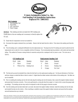
NOTE: Tensioner bracket-to-supercharger stud must be removed, or
supercharger cannot be lifted high enough to clear lower
intake manifold locator pins. See Fig. 1.
4) Remove throttle body from supercharger. Remove
supercharger-to-intake manifold bolts and remove supercharger. Remove
supercharger gasket and coolant passage "O" rings.
Fig. 1: Identifying Supercharger Components (3.8L - VIN 1)
Courtesy of General Motors Corp.
Installation
Ensure locator pins are in their proper location on intake

manifold. Replace gaskets and "O" rings. DO NOT use any type of
sealant on gasket. To complete installation, reverse removal
procedure. Tighten supercharger-to-intake manifold bolts to 17 ft.
lbs. (23 N.m). Tighten fuel rail retaining bolts to 89 INCH lbs. (10
N.m).
COMPUTERIZED ENGINE CONTROLS
ELECTRONICALLY ERASABLE PROGRAMMABLE READ ONLY MEMORY
Electronically Erasable Programmable Read Only Memory
(EEPROM) is a permanent memory that is part of PCM. EEPROM cannot be
replaced. EEPROM contains program and calibration information that PCM
uses to control powertrain. If PCM is replaced, ensure NEW PCM
software/calibration is correct and most recent version for vehicle.
EEPROM must be programmed when NEW PCM is installed. Program EEPROM
using latest software for that specific vehicle.
POWERTRAIN CONTROL MODULE
CAUTION: Electronic components used in control systems are designed to
carry very low voltages. As little as a 30-volt charge
created by static electricity can cause a total or degrading
failure in PCM or other electronic components containing
integrated circuits. Before servicing Powertrain Control
Module (PCM), technician must ground himself and the work
area to discharge static electricity.
CAUTION: Do not remove part from packaging until ready to install.
Ground any static-proof package before opening. Do not touch
electrical terminals of components unless properly grounded.
Do not lay electrical components on car seat, carpeting or
dashboard. Use electrostatic protection mat and ground strap
whenever possible.
NOTE: Before replacing PCM, carefully inspect all wiring and
control components. Failure to test for short circuits may
result in repeated PCM failure due to shorts. To prevent
internal damage to PCM, ensure ignition is off when
connecting or disconnecting PCM harness connectors or any
electrical components.
Removal & Installation (1.3L - "M" Body)
Turn ignition off. Disconnect negative battery cable. Open
glove box. Apply pressure to sides of glove box to disengage 2 clips.
Pull glove box down. Remove 3 bolts and PCM bracket. Disconnect
harness connectors from PCM. Remove PCM. To install, reverse removal
procedure.
Removal & Installation (1.8L - "S" Body)
1) Turn ignition off. Disconnect negative battery cable.
Remove glove box. Remove console support bracket. Remove left lower
finish panel and backing panel. Remove center finish panel. Remove
radio.
2) Remove 2 bolts in rear console box. Remove 2 screws on
sides of center console. Slide rear portion of center console back
toward rear seats. Remove 2 upper screws on front position of console
and remove front portion of console.
3) Disconnect harness connectors from PCM. Remove mounting
bolts from PCM. Remove PCM. To install, reverse removal procedure.
Removal & Installation (1.9L - Saturn "S" Series)

Disconnect negative battery cable. Locate PCM. See
PCM LOCATION table. Unlock 28-pin PCM harness connector and
disconnect. Remove bolt from 80-pin PCM harness connector and
disconnect. Remove PCM mounting bolts and remove PCM. To install,
reverse removal procedure. Tighten PCM mounting bolts to 80 INCH lbs.
(9 N.m). Tighten PCM harness connector bolt to 71 INCH lbs. (8 N.m).
Program replacement PCM using appropriate equipment and latest
software. See COMPUTER RELEARN PROCEDURES article in GENERAL
INFORMATION.
Removal & Installation (2.2L & 2.4L - "J" & "N" Bodies)
Turn ignition off. Disconnect negative battery cable. Locate
PCM. See PCM LOCATION table. Remove any necessary components to gain
access to PCM. Disconnect harness connectors from PCM. Remove PCM
mounting bolts (if equipped). Remove PCM. To install, reverse removal
procedure. Transfer any necessary components (i.e., knock sensor
module, etc.) to new PCM before installation. Program replacement PCM
using appropriate equipment and latest software. See COMPUTER RELEARN
PROCEDURES article in GENERAL INFORMATION.
Removal & Installation (2.2L, 3.0L, 3.1L, 3.4L, 3.5L, 3.8L,
4.0L, 4.6L & 5.7L)
Turn ignition off. Disconnect negative battery cable. Locate
PCM. See PCM LOCATION table. Remove any necessary components to gain
access to PCM. Disconnect harness connectors from PCM. Remove PCM
mounting bolts (if equipped). Remove PCM. To install, reverse removal
procedure. Transfer any necessary components (i.e., knock sensor
module, etc.) to new PCM before installation. Program replacement PCM
using appropriate equipment and latest software. See COMPUTER RELEARN
PROCEDURES article in GENERAL INFORMATION.
PCM LOCATION
Application Location
1.3L .............................................. Behind Glove Box
1.8L ................. Under Instrument Panel, Behind Center Console
1.9L ........................ In Engine Compartment, Next To Battery
2.2L & 2.4L (Cavalier & Sunfire) ......... Inside Right Front Fender
2.2L (Saturn) ..................................... Behind Glove Box
2.4L (Alero & Grand Am) .............. Under Left Side Of Instrument
Panel, Near Steering Column
3.0L (Catera) ............................... On Left Side Of Engine
Compartment, In ECM Housing
3.0L (Saturn) ....................... Mounted On Left Rear Of Engine
3.1L (Century & Grand Prix) ................. On Left Side Of Engine
Compartment, In Air Cleaner Assembly
3.1L (Malibu) ........................ Under Left Side Of Instrument
Panel, Near Steering Column
3.1L (Lumina) .............................. On Right Side Of Engine
Compartment, Forward Of Strut Tower
3.4L (Alero & Grand Am) .............. Under Left Side Of Instrument
Panel, Near Steering Column
3.4L (Impala & Monte Carlo) ................ On Right Side Of Engine
Compartment, In Air Cleaner Assembly
3.5L ........................................ On Left Side Of Engine
Compartment, In Air Cleaner Assembly
3.8L (Bonneville, Grand Prix,
LeSabre, Park Avenue & Regal) .............. On Left Side Of Engine
Compartment, In Air Cleaner Assembly
3.8L (Camaro & Firebird) ................... On Right Side Of Engine
Compartment, Rear Of Wheelhouse
3.8L (Impala & Monte Carlo) ................ On Right Side Of Engine

Compartment, Inside Air Cleaner Assembly
4.0L ........................................ On Left Side Of Engine
Compartment, In Air Cleaner Assembly
4.6L ................................ In Left Front Corner Of Engine
Compartment, Under Air Cleaner
5.7L (Camaro & Firebird) ................... On Right Side Of Engine
Compartment, Rear Of Wheelhouse
5.7L (Corvette) ........... Behind Right Front Fender, Under Battery
ENGINE SENSORS & SWITCHES
OXYGEN SENSORS
NOTE: Oxygen sensor is mounted in exhaust pipe, below exhaust
manifold and is equipped with a permanent pigtail which must
remain intact when removing sensor.
Removal (1.3L, 1.8L, 1.9L, 2.2L, 2.4L, 3.0L, 3.1L & 3.4L -
Sensor 1)
1) Ensure oxygen sensor is free of contaminants. DO NOT use
cleaning solvents of any type. Oxygen sensor may be difficult to
remove when engine temperature is less than 120
F (48 C). Excessive
removal force may damage threads in exhaust manifold or pipe.
2) Disconnect negative battery cable. Disconnect harness
connector from oxygen sensor. Carefully remove oxygen sensor from
exhaust pipe.
Removal (1.8L - Sensor 2)
1) Ensure oxygen sensor is free of contaminants. DO NOT use
cleaning solvents of any type. Oxygen sensor may be difficult to
remove when engine temperature is less than 120
F (48 C). Excessive
removal force may damage threads in exhaust manifold or pipe.
2) Disconnect negative battery cable. Remove front floor
console. Pull back passenger side carpet from along console floor
area. Disconnect oxygen sensor electrical connector. Remove oxygen
sensor wiring from under floor heat duct.
3) Raise and support vehicle. Remove oxygen sensor wiring
from body plug and floor pan. Carefully remove oxygen sensor from
exhaust pipe.
Removal (3.5L - Sensor 2)
1) Ensure oxygen sensor is free of contaminants. DO NOT use
cleaning solvents of any type. Oxygen sensor may be difficult to
remove when engine temperature is less than 120
F (48 C). Excessive
removal force may damage threads in exhaust manifold or pipe.
2) Raise and support vehicle. Disconnect negative battery
cable. Remove oxygen sensor wiring harness heat shield. Disconnect
oxygen sensor electrical connector. Carefully remove oxygen sensor
from exhaust pipe.
Removal (3.8L - Sensor 1)
1) Ensure oxygen sensor is free of contaminants. DO NOT use
cleaning solvents of any type. Oxygen sensor may be difficult to
remove when engine temperature is less than 120
F (48 C). Excessive
removal force may damage threads in exhaust manifold or pipe.
2) Remove fuel injector sight shield. Remove retaining clip.
Disconnect oxygen sensor electrical connector. Carefully remove oxygen
sensor from exhaust pipe.
Removal (3.8L - Sensor 2)
1) Ensure oxygen sensor is free of contaminants. DO NOT use

cleaning solvents of any type. Oxygen sensor may be difficult to
remove when engine temperature is less than 120
F (48 C). Excessive
removal force may damage threads in exhaust manifold or pipe.
2) Raise and support vehicle. Remove splash shield.
Disconnect retaining tab from connector. Disconnect oxygen sensor
electrical connector. Carefully remove oxygen sensor from exhaust
pipe.
Removal (4.0L & 4.6L - Bank 1 Sensor 1)
1) Ensure oxygen sensor is free of contaminants. DO NOT use
cleaning solvents of any type. Oxygen sensor may be difficult to
remove when engine temperature is less than 120
F (48 C). Excessive
removal force may damage threads in exhaust manifold or pipe.
2) Raise and support vehicle. Disconnect negative battery
cable. Support rear of powertrain. Remove rear frame bolts. Lower
frame 3". Disconnect rear oxygen sensor electrical connector. Remove
rear oxygen sensor.
Removal (4.0L & 4.6L - Bank 1 Sensor 2)
1) Ensure oxygen sensor is free of contaminants. DO NOT use
cleaning solvents of any type. Oxygen sensor may be difficult to
remove when engine temperature is less than 120
F (48 C). Excessive
removal force may damage threads in exhaust manifold or pipe.
2) Disconnect negative battery cable. Disconnect harness
connector from oxygen sensor. Carefully remove oxygen sensor from
exhaust pipe.
Removal (4.0L & 4.6L - Bank 2 Sensor 1)
1) Ensure oxygen sensor is free of contaminants. DO NOT use
cleaning solvents of any type. Oxygen sensor may be difficult to
remove when engine temperature is less than 120
F (48 C). Excessive
removal force may damage threads in exhaust manifold or pipe.
2) Raise and support vehicle. Disconnect negative battery
cable. Remove front splash shield. Disconnect front oxygen sensor.
Remove oxygen sensor.
Removal (5.7L)
NOTE: Procedure applies to all oxygen sensors (4).
1) Ensure oxygen sensor is free of contaminants. DO NOT use
cleaning solvents of any type. Oxygen sensor may be difficult to
remove when engine temperature is less than 120
F (48 C). Excessive
removal force may damage threads in exhaust manifold or pipe.
2) Raise and support vehicle. Disconnect oxygen sensor
electrical connector. Carefully remove oxygen sensor. For Camaro and
Firebird sensor locations, see Figs. 3-6. For Corvette sensor
locations, see Figs. 7-9.
CAUTION: Correct torque of oxygen sensor is critical to prevent
crushing glass beads in graphite anti-seize compound.
Crushing glass beads will cause sensor to seize in exhaust
manifold. This may necessitate replacement of exhaust
manifold upon next removal.
Installation
1) Whenever an oxygen sensor is removed, coat threads with
anti-seize compound before installation. New oxygen sensors already
have this compound applied to threads.
2) Install oxygen sensor. Tighten oxygen sensor to
specification. See TORQUE SPECIFICATIONS. Reconnect harness connector
to oxygen sensor. Reconnect negative battery cable.

OXYGEN SENSOR LOCATIONS
Application Location
1.3L
Sensor 1 ................................... On Exhaust Manifold
Sensor 2 ....................................... On Exhaust Pipe
1.8L
Sensor 1 ....................................... On Exhaust Pipe
Sensor 2 ................................. Under Passenger Floor
1.9L
Sensor 1 ................................... On Exhaust Manifold
Sensor 2 ....................................... On Exhaust Pipe
2.2L & 2.4L
Sensor 1 ................................... On Exhaust Manifold
Sensor 2 ....................................... On Exhaust Pipe
2.2L (Saturn)
Sensor 1 ................................... On Exhaust Manifold
Sensor 2 ....................................... On Exhaust Pipe
3.0L (Catera) ................................................ ( 1)
3.0L (Saturn)
Sensor 1 ................................... On Exhaust Manifold
Sensor 2 ....................................... On Exhaust Pipe
3.1L
Sensor 1 ................................... On Exhaust Manifold
Sensor 2 ....................................... On Exhaust Pipe
3.4L
Sensor 1 ................................... On Exhaust Manifold
Sensor 2 ....................................... On Exhaust Pipe
3.5L
Sensor 1 ................................... On Exhaust Manifold
Sensor 2 ....................................... On Exhaust Pipe
3.8L
Sensor 1 ................................... On Exhaust Manifold
Sensor 2 ....................................... On Exhaust Pipe
4.0L
Bank 1 Sensor 1 .......................... Rear Exhaust Manifold
Bank 1 Sensor 2 ................................ On Exhaust Pipe
Bank 2 Sensor 1 ......................... Front Exhaust Manifold
4.6L
Bank 1 Sensor 1 .......................... Rear Exhaust Manifold
Bank 1 Sensor 2 ................................ On Exhaust Pipe
Bank 2 Sensor 1 ......................... Front Exhaust Manifold
5.7L (Camaro & Firebird) ..................................... ( 1)
5.7L (Corvette) .............................................. ( 1)
(1) - For oxygen sensor locations, see Figs. 2 - 9.

Fig. 2: Locating Heated Oxygen Sensors (Catera)
Courtesy of General Motors Corp.

Fig. 3: Locating Bank 1 Sensor 1 Heated Oxygen Sensor (5.7L -
Camaro & Firebird)
Courtesy of General Motors Corp.

Fig. 4: Locating Bank 1 Sensor 2 Heated Oxygen Sensor (5.7L -
Camaro & Firebird)
Courtesy of General Motors Corp.
Fig. 5: Locating Bank 2 Sensor 1 Heated Oxygen Sensor (5.7L -
Camaro & Firebird)
Courtesy of General Motors Corp.

Fig. 6: Locating Bank 2 Sensor 2 Heated Oxygen Sensor (5.7L -
Camaro & Firebird)
Courtesy of General Motors Corp.
Fig. 7: Locating Bank 1 Sensor 1 Heated Oxygen Sensor (Corvette)
Courtesy of General Motors Corp.

Fig. 8: Locating Bank 1 Sensor 2 & Bank 2 Sensor 2 Heated Oxygen
Sensors (Corvette)
Courtesy of General Motors Corp.
Fig. 9: Locating Bank 2 Sensor 1 Heated Oxygen Sensor (Corvette)
Courtesy of General Motors Corp.
COOLING SYSTEM

COOLING SYSTEM BLEEDING
CAUTION: Avoid spilling coolant mixture on engine parts. Coolant may
cause undue corrosion. If coolant is spilled during
procedure, rinse area with clean water.
(1.3L, 1.8L, 1.9L, 2.2L, 2.4L, 3.0L, 3.1L, 3.4L & 3.8L)
1) Fill radiator to base of radiator filler neck. Fill
coolant reservoir to FULL mark on reservoir. On 2.4L models, open
coolant air bleed valve until a continuous stream of coolant flows
from valve. Install reservoir hose to reservoir cap. Operate engine
until coolant reaches operating temperature. Operating temperature is
reached when, hoses feel warm and when coolant flows through radiator.
2) Add coolant to radiator until coolant level reaches
radiator filler neck. Install radiator cap.
(3.5L, 4.0L & 4.6L)
1) Refill cooling system. Start engine. Place heater and A/C
control in any A/C mode except Max and temperature at highest setting.
Allow engine to continue idling until lower radiator to water pump
hose is hot. Turn engine off.
2) Allow engine to cool. Recheck fluid level. Add as
necessary.
(5.7L - Camaro & Firebird)
1) Refill cooling system to half capacity with 100 percent
concentration of coolant. Refill remaining system capacity with water,
until fluid reaches bottom of filler neck.
2) Start engine. With pressure cap removed, idle engine until
normal operating temperature is reached. Close air bleed screw when
coolant is visible dripping from bleed screw. With engine still
idling, add coolant to radiator until coolant level reaches bottom of
fill neck. Install pressure cap.
(5.7L - Corvette)
1) Refill cooling system to half capacity with 100 percent
concentration of coolant. Refill remaining system capacity with water,
until fluid reaches bottom of filler neck.
2) Start engine and idle for one minute. Install surge tank
cap. Raise RPM level to 3000 in 30 second intervals until normal
operating temperature is reached. Turn off engine. Remove surge tank
cap.
3) Start engine. Idle for one minute. Fill surge tank .5"
(12.7 mm) above COLD FULL mark. Install surge tank cap. Raise RPM
level to 3000 in 30 second intervals until normal operating
temperature is reached. Turn off engine. Remove surge tank cap. Refill
coolant as necessary, .5" (12.7 mm) above COLD FULL mark.
IGNITION SYSTEM
CAMSHAFT POSITION SENSOR
Removal & Installation (1.8L)
Disconnect negative battery cable. Remove engine cover.
Remove camshaft position sensor mounting bolt and remove camshaft
position sensor. To install, reverse removal procedure. Tighten
camshaft position sensor bolt to specification. See
TORQUE SPECIFICATIONS.
Removal & Installation (1.3L, 1.9L, 2.4L, 3.8L, 4.0L & 4.6L)
Disconnect negative battery cable. Remove camshaft position

sensor mounting bolt and remove camshaft position sensor. To install,
reverse removal procedure. Tighten camshaft position sensor bolt to
specification. See TORQUE SPECIFICATIONS.
Removal & Installation (2.2L)
Disconnect negative battery cable. Remove air cleaner outlet
resonator. Remove camshaft position sensor mounting bolt and remove
camshaft position sensor. To install, reverse removal procedure.
Tighten camshaft position sensor bolt to specification. See
TORQUE SPECIFICATIONS.
Removal & Installation (3.0L)
Disconnect negative battery cable. Remove A/C low pressure
line bracket. Remove hold down bolts for wiring harness to intake
plenum to gain access to the sensor. Remove camshaft position sensor
mounting bolt and remove camshaft position sensor. To install, reverse
removal procedure. Tighten camshaft position sensor bolt to
specification. See TORQUE SPECIFICATIONS.
Removal & Installation (3.1L & 3.4L)
Disconnect negative battery cable. Remove power steering
pump. Remove camshaft position sensor mounting bolt and remove
camshaft position sensor. To install, reverse removal procedure.
Tighten camshaft position sensor bolt to specification. See
TORQUE SPECIFICATIONS.
Removal & Installation (3.5L)
Disconnect negative battery cable. Remove coolant recovery
tank mounting nuts. Move coolant recovery tank aside. Remove camshaft
position sensor mounting bolt and remove camshaft position sensor. To
install, reverse removal procedure. Tighten camshaft position sensor
bolt to specification. See TORQUE SPECIFICATIONS.
Removal & Installation (5.7L)
Disconnect negative battery cable. Remove intake manifold.
Remove camshaft position sensor mounting bolt and remove camshaft
position sensor. To install, reverse removal procedure. Tighten
camshaft position sensor bolt to specification. See
TORQUE SPECIFICATIONS.
CRANKSHAFT POSITION SENSOR (C3I)
Removal & Installation (3.8L)
1) Disconnect negative battery cable. Remove serpentine belt
from crankshaft pulley. Raise vehicle on hoist. Remove right front
tire and wheel assembly. Remove right inner fender access cover.
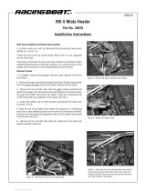
2) Using 28-mm socket, remove crankshaft harmonic balancer
bolt. Using Balancer Remover (J-38197), remove harmonic balancer.
Remove crankshaft position sensor shield (DO NOT use pry bar). See
Fig. 10. Disconnect crankshaft position sensor harness connector.
Remove crankshaft position sensor from engine block.
3) To install, reverse removal procedure. Apply Thread Sealer
(GM 1052080) onto threads of harmonic balancer bolt. Tighten sensor
and harmonic balancer bolts to specification. See
TORQUE SPECIFICATIONS. Perform CRANKSHAFT POSITION (CKP) SENSOR
VARIATION LEARN PROCEDURE. See COMPUTER RELEARN PROCEDURES article in
GENERAL INFORMATION.

Fig. 10: Removing Crankshaft Position Sensor Shield (C3I)
Courtesy of General Motors Corp.
CRANKSHAFT POSITION SENSOR (DIS & IDI)
Removal & Installation (1.3L, 1.8L, 1.9L, 2.2L, 2.4L, 3.5L,
4.0L, 4.6L & 5.7L)
1) Disconnect negative battery cable. On 3.5L and 5.7L
models, remove starter. On 4.0L and 4.6L models, remove oil filter
adapter. On all models, disconnect harness connector from crankshaft
position sensor. Remove crankshaft position sensor mounting bolt/nut
and remove crankshaft position sensor.
2) Inspect crankshaft position sensor "O" ring for wear,
cracks or other damage. Replace as necessary. Lubricate NEW "O" ring
with engine oil before installing. To install, reverse removal
procedure. Tighten crankshaft position sensor bolt/nut to
specification. See TORQUE SPECIFICATIONS.
Removal & Installation (3.0L)
1) Disconnect negative battery cable. Disconnect harness
connector from crankshaft position sensor. Attach piece of wire 36"
(91 cm) long to crankshaft position sensor pigtail. Raise and support
vehicle. Loosen oil cooler lines at engine block. Back out fittings

far enough in order to gain sufficient clearance for sensor pigtail
connector to pass between oil cooler lines and side of engine block.
2) Remove crankshaft position sensor connecting bolt. Remove
crankshaft position sensor and "O" ring from engine block. Using wire
attached to crankshaft position sensor pigtail, pass connector between
lines and block at point of widest gap. Stop when pull wire is exposed
at both ends of routing path.
3) Inspect crankshaft position sensor "O" ring for wear,
cracks or other damage. Replace as necessary. Lubricate NEW "O" ring
with engine oil before installing. To install, reverse removal
procedure. Tighten crankshaft position sensor bolt/nut to
specification. See TORQUE SPECIFICATIONS.
CRANKSHAFT (7X) POSITION SENSOR (DIS)
Removal & Installation (3.1L & 3.4L)
1) Disconnect negative battery cable. Turn steering wheel
fully to left. Raise and support vehicle. Disconnect crankshaft
position sensor harness connector. Remove crankshaft position sensor
mounting bolt. Remove crankshaft position sensor from engine block.
2) Inspect crankshaft position sensor "O" ring for wear,
cracks or other damage. Replace as necessary. Lubricate NEW "O" ring
with engine oil before installing. To install, reverse removal
procedure. Tighten crankshaft position sensor bolt to specification.
See TORQUE SPECIFICATIONS.
CRANKSHAFT (24X) POSITION SENSOR (DIS)
Removal & Installation (3.1L & 3.4L)
1) Disconnect negative battery cable. Remove serpentine belt
from crankshaft pulley. Raise and support vehicle.
2) Remove crankshaft harmonic balancer bolt. Using Balancer
Remover (J-24420-B), remove harmonic balancer. Disconnect crankshaft
position sensor harness connector. Remove crankshaft position sensor
bolts. Remove crankshaft position sensor.
3) To install, reverse removal procedure. Apply Thread Sealer
(GM 1052080) onto threads of harmonic balancer bolt. Tighten
crankshaft position sensor and harmonic balancer bolts to
specification. See TORQUE SPECIFICATIONS.
IGNITION COIL (DIS)
Removal & Installation (1.3L & 1.8L)
Disconnect negative battery cable. Remove spark plug wires
from ignition coils. Disconnect harness connectors from ignition
coils. Remove bolts attaching ignition coils to cylinder head. Remove
ignition coils. To install, reverse removal procedure.
Removal & Installation (1.9L, 2.2L, 3.0L, 3.1L & 3.4L)
Disconnect negative battery cable. Remove spark plug wires
from ignition coils. On 3.0L, remove screws attaching ignition coils
to support bracket. On all models except 3.0L, remove nuts or screws
attaching ignition coils to ignition control module. On all models,
remove ignition coils. To install, reverse removal procedure.
IGNITION COIL (IDI)
Removal & Installation (2.4L)
1) Disconnect negative battery cable. Disconnect 11-pin
harness connector. Remove 4 IDI cover assembly-to-camshaft housing
bolts. Remove ignition system assembly from engine. Remove 4 coil
housing-to-cover screws. Remove housing cover.

2) Disconnect coil harness connector from module. Remove
ignition coil, contacts and seals from cover. To install, reverse
removal procedure. Tighten screws and bolts to specification. See
TORQUE SPECIFICATIONS.
Removal & Installation (3.5L, 4.0L, 4.6L & 5.7L)
NOTE: Ignition control module and ignition coil can not be serviced
separately. Replace module and coil as an assembly.
For ignition coil removal and installation, see
IGNITION CONTROL MODULE (IDI).
IGNITION COIL (C3I)
Removal & Installation (3.8L)
Disconnect negative battery cable. Disconnect spark plug
wires from coil pack. Remove 6 screws retaining coils to ignition
control module. Remove ignition coils from module. To install, reverse
removal procedure. Tighten retaining screws to specification. See
TORQUE SPECIFICATIONS.
IGNITION CONTROL MODULE (C3I)
Removal & Installation (3.8L)
1) Disconnect negative battery cable. Disconnect 14-pin
connector at ignition control module. Disconnect spark plug wires from
coil pack. Remove 6 screws retaining coils to ignition control module.
Remove ignition coils from module.
2) Remove screws and washers securing ignition control module
to bracket. Remove ignition control module. To install, reverse
removal procedure. Tighten retaining screws to specification. See
TORQUE SPECIFICATIONS.
IGNITION CONTROL MODULE (DIS)
Removal & Installation (1.9L, 2.2L, 3.1L & 3.4L)
1) Disconnect negative battery cable. Disconnect connectors
at ignition control module. See Fig. 11. Disconnect spark plug wires
from coil pack. Remove coil pack/ignition control module assembly. For
ignition control module location, see COMPONENT LOCATIONS in
appropriate SYSTEM & COMPONENT TESTING article. Separate ignition
coil(s) from ignition control module (if possible).
2) To install, reverse removal procedure. Tighten ignition
control module mounting bolts/nuts. On 1.9L, ensure mounting bolt
holes are clean of old sealant. Use NEW mounting bolts supplied with
module. On all models, tighten mounting bolts/nuts to specification.
See TORQUE SPECIFICATIONS.
Fig. 11: Locating Distributorless Ignition Control Module
Components (2.2L Shown; 1.9L Is Similar)
Courtesy of General Motors Corp.

Fig. 12: Locating Distributorless Ignition Control Module
Components (3.1L & 3.4L)
Courtesy of General Motors Corp.
IGNITION CONTROL MODULE (IDI)
CAUTION: If spark plug boots adhere to spark plugs, use Boot Remover
(J-36011). Twist first, and then pull upward. Boots must be
in place on housing before installing ignition system
assembly, or damage may result.
Removal (2.4L)
1) Disconnect negative battery cable. Disconnect 11-pin
harness connector. Remove 4 IDI cover assembly-to-camshaft housing
bolts. Remove ignition system assembly from engine.
2) Remove 4 coil housing-to-cover screws. Remove housing
cover. Remove coil harness connector from module. Remove module-to-
cover screws. Remove module from cover.
NOTE: DO NOT wipe grease from module or coil if module is not being
replaced. If installing a NEW module, spread silicone grease
on metal face of module and on cover where module seats.
Grease is included with NEW module and is necessary for
module cooling purposes.
Installation
To install, reverse removal procedure. Tighten screws and
bolts to specification. See TORQUE SPECIFICATIONS.
NOTE: Ignition control module and ignition coil can not be serviced
separately. Replace module and coil as an assembly.
Removal & Installation (3.5L)

1) Disconnect negative battery cable. Disconnect electrical
connector from ignition control module (ICM). Remove cover from coils.
Remove ICM screws. Remove ignition control module.
2) To install, reverse removal procedure. Tighten screws to
specification. See TORQUE SPECIFICATIONS.
NOTE: Ignition control module and ignition coil cannot be serviced
separately. Replace module and coil as an assembly.
Removal & Installation (4.0L & 4.6L)
1) Disconnect negative battery cable. Remove fuel injector
sight shield. Remove AIR control valve. Disconnect electrical
connector from ignition control module (ICM). Remove cover from coils.
Remove ICM screws. Remove ignition control module.
2) To install, reverse removal procedure. Tighten screws to
specification. See TORQUE SPECIFICATIONS.
Removal & Installation (5.7L)
1) Disconnect negative battery cable. Remove fuel rail cover.
Disconnect electrical connector from Ignition Control Module (ICM).
Remove cover from coils. Remove ICM screws. Remove ignition control
module.
2) To install, reverse removal procedure. Tighten screws to
specification. See TORQUE SPECIFICATIONS.
KNOCK SENSORS
Removal & Installation (1.8L & 1.9L)
Disconnect negative battery cable. Remove intake manifold.
See appropriate article in ENGINES. Disconnect knock sensor electrical
connector. Remove knock sensor. To install, reverse removal procedure.
Tighten knock sensor to specification. See TORQUE SPECIFICATIONS.
Removal & Installation (2.2L)
Disconnect negative battery cable. Remove air cleaner outlet
resonator. Disconnect knock sensor electrical connector. Remove knock
sensor. To install, reverse removal procedure. Tighten knock sensor to
specification. See TORQUE SPECIFICATIONS.
Removal & Installation (2.4L)
Disconnect negative battery cable. Raise and support vehicle.
Loosen knock sensor fastener. Disconnect knock sensor electrical
connector. Remove knock sensor. To install, reverse removal procedure.
Tighten knock sensor to specification. See TORQUE SPECIFICATIONS.
Removal & Installation (3.0L - Knock Sensor 1)
Disconnect negative battery cable. Disconnect knock sensor
electrical connector. Remove generator and drive belt tensioner.
Remove knock sensor pigtail from retaining clips on rear timing belt
cover. Remove bolt in center of knock sensor. Remove knock sensor. To
install, reverse removal procedure. Tighten knock sensor to
specification. See TORQUE SPECIFICATIONS.
Removal & Installation (3.0L - Knock Sensor 2)
Disconnect knock sensor connector. Remove power steering pump
pulley. Remove knock sensor pigtail from retaining clips. Attach scrap
piece of wire about 36" (90 cm) to knock sensor pigtail. Remove left
engine mount. Remove fastening bolts for engine mount bracket and
remove bracket from block. Gently pull knock sensor pigtail through
wiring conduit and out. Stop when the pull wire is free of conduit at
both ends. Detach knock sensor from pull wire, leaving pull wire in
place. To install, reverse removal procedure. Reroute knock sensor
using pull wire left in place after removal. Tighten knock sensor to

specification. See TORQUE SPECIFICATIONS.
Removal & Installation (3.1L & 3.4L)
Disconnect negative battery cable. Raise and support vehicle.
Disconnect knock sensor electrical connector. Remove knock sensor. To
install, reverse removal procedure. Tighten knock sensor to
specification. See TORQUE SPECIFICATIONS.
Removal & Installation (3.5L)
Disconnect negative battery cable. Remove right front wheel.
Disconnect and reposition jumper harness connector. Disconnect knock
sensor electrical connector. Remove knock sensor. To install, reverse
removal procedure. Tighten knock sensor to specification. See
TORQUE SPECIFICATIONS.
Removal & Installation (3.8L - Knock Sensor 1)
Disconnect negative battery cable. Drain cooling system.
Raise and support vehicle. Disconnect knock sensor electrical
connector. Remove knock sensor. To install, reverse removal procedure.
Tighten knock sensor to specification. See TORQUE SPECIFICATIONS.
Removal & Installation (3.8L - Knock Sensor 2)
Disconnect negative battery cable. Drain cooling system.
Raise and support vehicle. Remove splash shield bolts. Remove knock
sensor heat shield. Disconnect knock sensor electrical connector.
Remove knock sensor. To install, reverse removal procedure. Tighten
knock sensor to specification. See TORQUE SPECIFICATIONS.
Removal & Installation (4.0L, 4.6L & 5.7L)
Disconnect negative battery cable. Remove intake manifold.
See appropriate article in ENGINES. Disconnect knock sensor electrical
connector. Remove knock sensor. To install, reverse removal procedure.
Tighten knock sensor to specification. See TORQUE SPECIFICATIONS.
FUEL SYSTEMS
FUEL SYSTEM PRESSURE RELEASE (CNG)
WARNING: Always relieve fuel pressure before disconnecting any fuel
injection-related component. DO NOT allow fuel to contact
engine or electrical components.
NOTE: Replace all "O" rings that are disconnected or loosened.
1) Connect scan tool to Data Link Connector (DLC). Clear all
existing DTC’s. Start engine and verify engine is operating on CNG.
Using scan tool, select High Pressure Lock-Off (HPL) output control.
See Fig. 13. Close HPL and observe the Fuel Pressure Sensor parameter
on scan tool. If Fuel Pressure Sensor parameter fails to decrease, go
to next step. When engine stalls, turn ignition off. Remove CNG 20-amp
fuse. Slowly open fuel line fittings in order to release remaining
pressure.
2) Remove fuel tank cover dust plug. Close manual lock-down
screw located on HPL manual shutoff fitting by rotating the Allen
screw clockwise until fully seated. Turn ignition off. Disconnect
negative battery cable. Loosen fuel line fitting at Low Pressure Lock-
Off (LPL) inlet port several turns. Do not remove fitting. If fuel is
not venting with LPL inlet fitting loosened, relieve fuel line tension
by pulling line away from LPL.
3) Loosen fuel line fitting at HPL inlet port several turns.
Do not remove fitting. Relieve fuel line tension by pulling line away
from HPL. Pressure is released when fuel line can be pulled away from
/