DAN DRYER 3492 User manual

Type
User manual

DAN DRYER 3492 is a user-friendly hand sanitizer dispenser that ensures optimal hand hygiene. With its infrared sensor, it delivers a precise dosage of 1-1.2 ml of disinfectant gel when hands are placed within the 2-10 cm range. The dispenser holds a 5 liter bottle and provides up to 5000 activations. It features a light indicator for standby, active, and sensor obstruction status. Easy to install and maintain, it's ideal for various public spaces.

DAN DRYER 3492 is a user-friendly hand sanitizer dispenser that ensures optimal hand hygiene. With its infrared sensor, it delivers a precise dosage of 1-1.2 ml of disinfectant gel when hands are placed within the 2-10 cm range. The dispenser holds a 5 liter bottle and provides up to 5000 activations. It features a light indicator for standby, active, and sensor obstruction status. Easy to install and maintain, it's ideal for various public spaces.

USER MANUAL
COLUMN JUNIOR
MODEL: 3492/3493/3494 (ADAPTER)
MODEL: 3496/3497/3498 (BATTERY)
200 300
167
200
240 340
300
167
482
DAN
DAN
DRYER
DRYER
TECHNICAL SPECIFICATIONS
DESCRIPTION DATA
Material Steel
Voltage (adapter version) 6V DC, 230VAC/6VDC adapter included
Voltage (battery version) 6V DC, battery box (included) for 4x D-type LR20 batteries (not
included)
Sensor type Infrared, self adjusting
Sensor range Preset at 100 mm
Dosage amount 1-1.2 ml (4100-5000 activations / 5 litre bottle)
Pump life 100,000 activations
Mechanism life 500,000 activations
Bottle 5 l
Net weight 11.55 kg
Gross weight 13.50 kg
PRODUCT TYPE / MODEL
Adapter
3492 Sanitiser stand, white
3493 Sanitiser stand, black
3494 Sanitiser stand, RAL Classic
IMPORTANT!
This product falls within the scope of the WEEE directive
on recycling and recovery of waste electrical and electronic
equipment.
This product should not be disposed of with general household waste
This product must be reused if possible
Contact your local authority for further details
This product may also be returned to the manufacturer/retailer for proper treatment,
recovery, and recycling
Dimensions and technical specications 3
General safety information 4
Installation 5
Replacement of battery and pump 9
Application 11
Light indicator 11
Cleaning and maintenance 12
Replacement of disinfectant bottle 12
Troubleshooting and corrective actions 13
Parts list 14
TABLE OF CONTENTS DIMENSIONS AND TECHNICAL SPECIFICATIONS
Dimensions
Unit of measurement: mm
Battery
3496 Sanitiser stand, white
3497 Sanitiser stand, black
3498 Sanitiser stand, RAL Classic
2 3
DAN
DAN
DRYER
DRYER
EMKA
DAN
DAN
DRYER
DRYER
!
NOTE
If the power cord is damaged, it must be replaced immediately. Disconnect the electricity
supply cord according to instructions.
This product is not intended for use by persons (inclusive children) with reduced physical,
sensory or mental capabilities, or lack of experience and knowledge, unless they are
supervised or have been given instructions concerning use of the product by a person
responsible for their safety.
Children should be supervised to ensure this product is used correctly.
GENERAL SAFETY INFORMATION INSTALLATION
Make sure the main breaker is turned off. Installation must be carried out by a qualied
person in accordance with applicable standards in the country concerned.
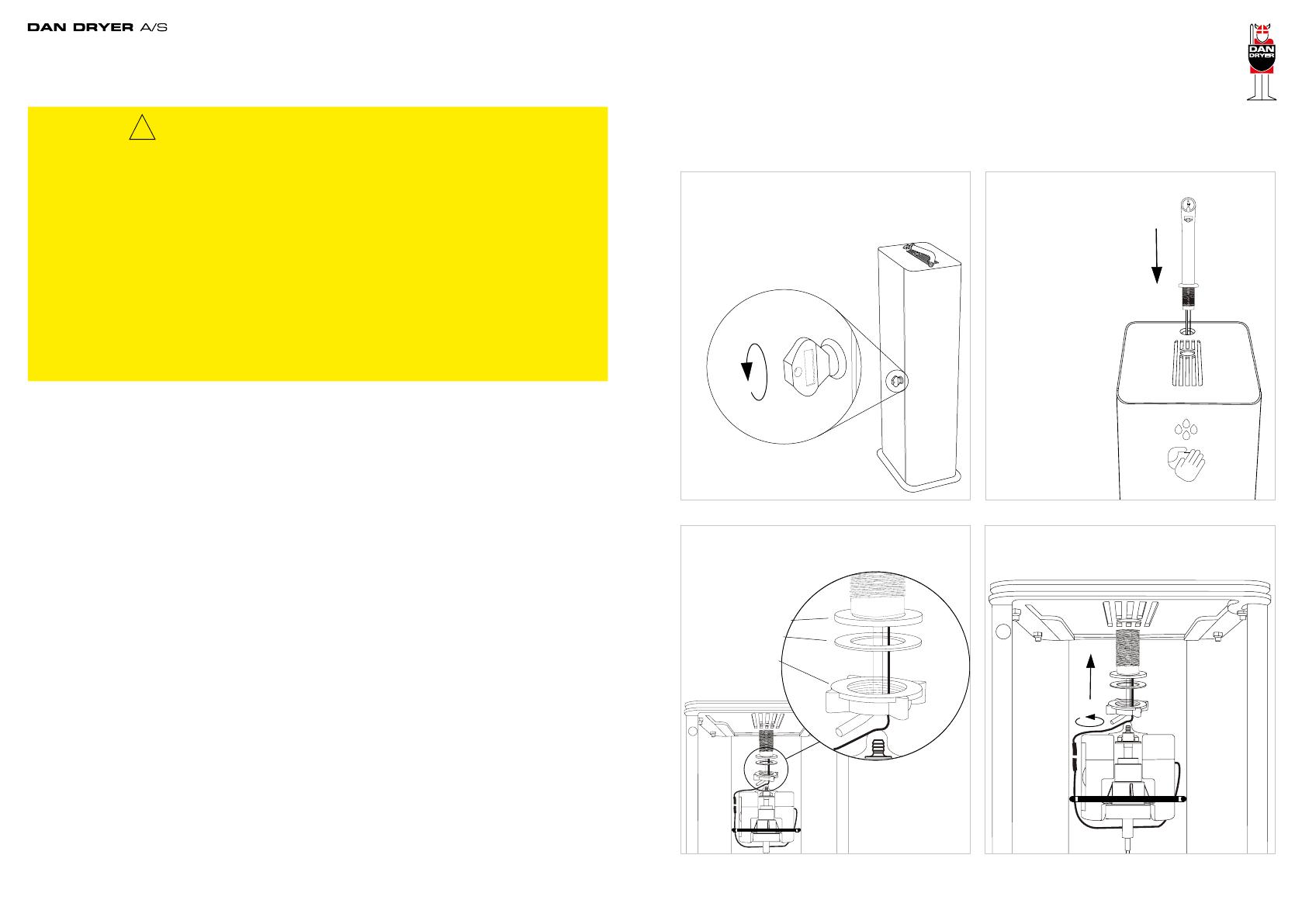
4) Place faucet in the centre before tightening
the nut. Do not use any tools.
3) Pull tube and wire through the rubber gasket,
nylon bushing, and clamping nut.
1) Use the special key supplied to open the
door.
2) Pull wire, plastic tube,
and faucet coupling through
the hole in the top plate.
Rubber gasket
Nylon bushing
Clamping nut
WARNING
Turn off the power to the unit before servicing or cleaning
Never make alterations to the product
Never insert objects into any opening in the product
The product is not intended for playing purposes
Cleaning and maintenance only by qualied persons
The product may only be used for the applications described in this manual
Do not use any accessories not recommended by the manufacturer
The product should be checked on a regular basis. Never use a defective or
malfunctioning unit
Never make alterations to the product affecting its performance. DAN DRYER’s product
warranty does not cover product problems that result from misuse or alteration
4 5
INSTALLATION
9,1B) Connect to external battery box. Install
battery box on backplate bracket in the lower
storage space. Tighten using the butterfly nut.
9,2B) Push cable through the rack via the cable
lead-in.
9,1A) Connection with adapter. Push cable
through the cable lead-in at the bottom of
COLUMN.
9,2A) Push cable further upward and through
the ’rack’.
BATTERY (MODEL 3496-3498)
ADAPTER (MODEL 3492-3494) ADAPTER (MODEL 3492-3494)
BATTERY (MODEL 3496-3498)
INSTALLATION
5) Attach the transparent plastic hose to the
pump nozzle piece.
6) Pay attention to power plug orientation pin.
7) Connect the plugs on the wires
between faucet and control box.
8) Insert drip tray in the support rails, lengthwise,
under the top plate.
Power plug orientation pin
Butterfly nut
6 7
DAN
DRYER
ALKALINE
TYPE D LR20 1,5V
ALKALINE
TYPE D LR20 1,5V
ALKALINE
TYPE D LR20
1,5V
ALKALINE
TYPE D LR20
1,5V
INSTALLATION
13) Close front cover and the unit is
ready for use.
10) Power connection to box. Connect plug to
the control box.
12) Place the 5 litre bottle on the rack. Insert
the tube through the hole in the lid and into the
bottle.
11) Take off 5 litre bottle screw lid. We
recommend you drill a Ø7 hole for the hose.
Or remove the lid completely.
Ø7 mm
REPLACEMENT OF BATTERIES AND PUMP
14) Open the battery pack with a
screwdriver PH2.
15) Replace (4) D-batteries in the
battery pack.
16) Replacement of pump unit. Remove
tube from pump unit.
17) Detach clip from hooks as shown.
8 9
REPLACEMENT OF BATTERIES AND PUMP
21) Attach tube to the new pump unit.
18) Remove existing pump unit. 19) Insert new pump. Make sure the pump
guideways t those of the control box. See
illustrations.
20) Attach the clip on the hooks as shown.
Ensure easy access to cleaning and maintenance of the
product
Do not bend the plastic tube too sharp. It will cause
reduced dosage or total block total blockage in ture
Ensure the unit is placed on a rm and stable base
IMPORTANT!
PRODUCT APPLICATION
Place hands approx 2-10 cm under the sensor to activate the
dispenser. The dispenser will release 1-1.2 ml. disinfectant gel
Move hands away after disinfectant release
Stops automatically when hands are moved away
LIGHT INDICATOR (ADAPTER)
Standby Red light
Active Green light
Obstruction of sensor Flashing green and red light
LIGHT INDICATOR (BATTERIES)
Standby No light
Active Green light
Obstruction of sensor Flashing green and red light
10 11
CLEANING AND MAINTENANCE
Routine cleaning and maintenance is recommended
CLEANING AND MAINTENANCE OF CONTROL BOX
Cut the power
Remove any dust and dirt
Do not rinse with running water
Use a damp cloth and mild cleaning solution. Never use cleaning detergents with
an abrasive effect
CLEANING AND MAINTENANCE OF TAP/SENSOR
Do not rinse with running water
Use a damp cloth and mild cleaning solution. Never use cleaning detergents with
an abrasive effect
Clean sensor for dust and dirt to prevent unintentional activation
REPLACEMENT OF DISINFECTANT BOTTLE
Use the key supplied to open the door
Remove empty bottle from the rack
Replace with new bottle
Insert pump tube into the bottle
Close the door
TROUBLESHOOTING AND CORRECTIVE ACTIONS
SYMPTOM POTENTIAL CAUSE CORRECTIVE ACTION
No disinfectant is
delivered Low supply Rell the disinfectant bottle
Sensor window is dirty Clean the sensor window
Obstruction in front of the
sensor window Remove the obstruction
Damaged sensor Contact DAN DRYER for advice
Tube disconnected from pump If the end of the tube is damaged,
please remove the damaged part. The
undamaged tube is to be mounted on
the nozzle exit of the pump
Sensor cabling disconnected
from control box Check that the cable from the faucet
is installed correctly in the control box
Power supply has been
disconnected Check that the cable from the adapter
or the external battery box is installed
correctly in the control box (see page
7)
AC/DC adapter not connected Check that the AC/DC adapter is
plugged into the wall and is getting
power
The dispenser
activates
unintentionally
Sensor window is dirty Clean the sensor window
Obstruction in front of the
sensor window Remove the obstruction
Damaged sensor Contact DAN DRYER for advice
12 13
1
2
3
4
5
6
7
8
9
10
11
12
13
14
15
16
17 18
19
20
21
Parts inside lock
Parts inside faucet
22
No. Description
1 Faucet complete
2 End piece
3 Rubber ring
4 Holder for LED print and sensor
5 Rubber gasket (top)
6 Rubber gasket (bottom)
7 Nylon bushing
8 Clamping nut
9 Tube/nozzle connecting part
10 Nozzle for disinfectant
11 Tube 700mm
12 Control box (DC)
13 Pump for disinfectant
14 AC/DC adapter
15 External battery box
16 Lock complete
17 Housing
18 Front cover
19 Mounting base
20 Top plate
21 Drip tray
22 Collar band
PARTS LIST
14 15
DAN DRYER A/S
Alsikevej 8
DK - 8920 Randers NV
Tel: +45 8641 5711
Email: info@dandryer.dk
dandryer.com
  • Page 1 1
  • Page 2 2
  • Page 3 3
  • Page 4 4
  • Page 5 5
  • Page 6 6
  • Page 7 7
  • Page 8 8
  • Page 9 9

DAN DRYER 3492 User manual

Type
User manual

DAN DRYER 3492 is a user-friendly hand sanitizer dispenser that ensures optimal hand hygiene. With its infrared sensor, it delivers a precise dosage of 1-1.2 ml of disinfectant gel when hands are placed within the 2-10 cm range. The dispenser holds a 5 liter bottle and provides up to 5000 activations. It features a light indicator for standby, active, and sensor obstruction status. Easy to install and maintain, it's ideal for various public spaces.

Ask a question and I''ll find the answer in the document

Finding information in a document is now easier with AI