Page is loading ...

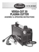
VERSA-CUT 20
PLASMA CUTTER
ASSEMBLY & OPERATING INSTRUCTIONS
Part #20062
Black
C 0
M 0
Y 0
K 100

✑✒✓✔
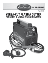
The Eastwood-designed Versa-Cut Plasma Cutter is a compact, lightweight yet powerful Plasma Cutter capable of cutting a range of material from the
thinnest steel and aluminum up to full 1/8" thick with ease and precision. A convenient Pilot Arc feature allows for instant plunge cutting.
DUTY CYCLE
The rated Duty cycle refers to the amount of plasma cutting that can be done within a measured amount of time. The Eastwood Cut-20 Plasma Cutter has a duty
cycle of 40% at 15 Amps.
It is easiest to look at your cutting time in blocks of 10 Minutes and the Duty Cycle being a percentage of that 10 Minutes. If cutting at 15 Amps with a 40% Duty
Cycle, within a 10 Minute block of time you can cut for 4 Minutes with 6 Minutes of cooling time allowed for the cutter.
SPECIFICATIONS
Amperage
Output
Range
Output
Voltage Weight
Duty
Cycle
Post
Flow
Pilot
Arc
Current
Pilot
Arc
Time Torch Type
Overall
Dimensions
Electrical
Input
Air
Requirements
15 ±1
Amps
85.9 V 14.75
Lbs
40%
@ 15 A
20 sec.
±2 sec.
Cycle
14±1
Amp
3 sec.
±.5 sec.
Trafi met S25K,
Electrode Size
= .65mm
19.5" (495mm) L
11.5" (292mm) W
13.5" (343mm) H
20 Amp,
120 VAC,
60 Hz
5-7 CFM
@ 60 psi
2
✑✒✓✔
✑✒✓✔
✑✒✓✔
✑✒✓✔
✑✒✓✔
✑✒✓✔
✑✒✓✔
✑✒✓✔

3
SAFETY INFORMATION
READ INSTRUCTIONS!
• Thoroughly read and understand this instruction manual before using the Plasma Cutter.
• Keep this instruction booklet.
ELECTRIC SHOCK CAN KILL!
• Improper use of a Plasma Cutter can cause electric shock, injury and death! Read all precautions described in this manual to reduce the
possibility of electric shock.
• Do not touch any electrical components that may be live.
• Separate yourself from the Plasma Cutter circuit by using insulating mats to prevent contact from the work surface.
• The Plasma Cutter power switch is to be in the OFF position and the power supply is to be disconnected when performing any mainte-
nance or consumable changes.
• Always wear dry, protective clothing and leather welding gloves and insulated footwear.
• Always operate the Plasma Cutter in a clean, dry, well ventilated area. Do not operate the Plasma Cutter in humid, wet, rainy or poorly
ventilated areas.
• Be sure that the work piece is properly supported and grounded prior to beginning an electric Plasma Cutter operation.
• The electrode and work (or ground) circuits are electrically “hot” when the welder is on. Do not touch these “hot” parts with your bare
skin or wet clothing.
• Disconnect from power supply before assembly, disassembly or maintenance of the torch or contact tip.
• Always attach the ground clamp to the piece to be welded and as close to the weld area as possible. This will give the least resistance
and best cut.
ELECTROMAGNETIC FIELDS MAY BE DANGEROUS!
• Anyone with a cardiac pacemaker or other implanted medical device should stay away from any plasma cutting before consulting a doc-
tor. Powerful electromagnetic fi elds emitted by Plasma Cutters can interfere with operation, causing malfunction and possible death.
• Exposure to electromagnetic fi elds while plasma cutting may have other health effects which are not known.
SAFETY INFORMATION
In this manual, on the labeling, and all other information provided with this product:
DANGER indicates a hazardous situation which, if not avoided, will result in death or serious injury.
WARNING indicates a hazardous situation which, if not avoided, could result in death or serious injury.
CAUTION indicates a hazardous situation which, if not avoided, could result in minor or moderate injury.
NOTICE is used to address practices not related to personal injury.
✑✒✓✔
✑✒✓✔

✑✒✓✔
✑✒✓✔
✑✒✓✔
4
SAFETY INFORMATION
FUMES AND CUTTING GASES CAN BE DANGEROUS!
• Do not breathe fumes that are produced by the cutting operation. These fumes are dangerous and can cause serious respiratory dam-
age. Keep your head and face out of cutting fumes.
• Always work in a properly ventilated area. Wearing an OSHA-approved respirator when cutting is recommended!
• Never cut coated materials including but not limited to: cadmium plated, galvanized, lead based paints.
CUTTING SPARKS CAN CAUSE FIRE OR EXPLOSION!
• Do not operate Plasma Cutter in areas where flammable or explosive vapors are present.
• Always keep a fire extinguisher nearby while cutting.
• Use welding blankets to protect painted surfaces, dash boards, engines, etc.
• Ensure power supply has properly rated wiring to handle power usage.
• Do not use on or near combustible surfaces.
• Remove all flammable items within 35 feet of the cutting arc.
ARC RAYS CAN BURN EYES AND SKIN!
• Use a shield with the proper filter (a minimum of #11) to protect your eyes from sparks and the rays of the arc when cutting or when
observing open arc cutting (see ANSI Z49.1 and Z87.1 for safety standards).
• Use suitable clothing made from durable flame-resistant material to protect your skin. Protect nearby individuals with a non-flammable
barrier.
• If other persons are in the area of cutting use welding screens to protect bystanders from sparks and arc rays.
HOT METAL WILL BURN!
• Electric cutting operations cause sparks and heat metal to temperatures that will cause severe burns!
• Use protective gloves and clothing when performing any Plasma Cutter operations. Always wear long pants, long-sleeved shirts and
leather welding gloves.
• Make sure that all persons in the cutting area are protected from heat, sparks and ultraviolet rays.
• Use additional face shields and flame resistant barriers as needed.
• Never touch work piece until it has completely cooled.
FLYING METAL CHIPS CAN CAUSE INJURY!
Cutting, brushing, hammering, chipping, and grinding can cause flying metal chips and sparks. To prevent injury wear approved
safety glasses.
✑✒✓✔
✑✒✓✔
✑✒✓✔
✑✒✓✔

REQUIRED ITEMS
Before you begin using The Eastwood Versa-Cut 20 Plasma Cutter make sure you have the following:
• A dedicated 20 Amp 120V circuit.
• A clean, dry air supply source for the torch. An air compressor capable of delivering 5-7 CFM @ 60 PSI is required. You can even use a portable
compressed air tank with regulator.
• The air supply must be completely free of moisture. The use of a moisture trap such as Eastwood Two Stage Desiccant Dryer System (#20473) or
equivalent is strongly recommended.
• Eastwood recommends at a minimum a properly grounded 110-120 VAC 60Hz, 20 Amp circuit. NOTE: Unit must be grounded to work properly and safely!
• A clean, safe, well-lit, dry, and well-ventilated work area.
• A non-flammable, long sleeve shirt or jacket.
• Heavy Duty Welding Gloves (#12590 or equivalent).
• Auto Darkening Welding Mask (#13203) or glasses (#13948) to provide eye protection during cutting operations.
POWER REQUIREMENTS
• The Eastwood Versa-Cut 20 Plasma Cutter is designed to operate on 110-120 VAC, and
requires a proper 20 Amp circuit.
• Use of an extension cord is not recommended. If an extension cord is required, do not
exceed 25' [7.5m]. All extension cords must be UL approved, 3 conductor grounded, 14
AWG or greater.
BEFORE YOU BEGIN
Remove all items from the box. Compare with list below to make sure unit is complete.
(1) Eastwood Versa-Cut 20 Plasma Cutter (1) Instruction Booklet
(1) Trafimet Style S25K Torch with 20' [6m] Supply Line (1) Extra Electrode
(1) 10' [3m], 120 VAC, 14 gauge grounded Power Cord (1) Extra Nozzle
(1) 10' [3m], Ground Lead and Clamp
SET-UP
• After a proper 20 Amp, 120 VAC, 60 Hz current source is determined, be sure the
appropriate circuitry and breakers are in place.
• DO NOT plug unit in at this time and make sure the Power Switch located on the upper right
corner of The Rear Panel is in the OFF position (FIG. A).
• Install a quick-disconnect air fitting compatible with your air line into the 1/4” NPT fitting
located on the upper left corner of the Rear Panel (FIG. A).
• Attach the Torch Air Supply Line to the lower right corner of the Front Panel by threading in
place. Note: “Finger-Tighten” securely but do not over tighten. (FIG. B&C).
• Attach the Torch Switch Connector Cable to the Multi-Pin Connector located second from
right of the Lower Front Panel (FIG. B&C). Note that the semi-circular notch of the inner
female plug must align with the semi-circular male key of the metal shell. Push plug securely in place then thread the metal locking ring in onto the metal
shell. “Finger-Tighten” securely but do not over tighten.
• Remove the Red threaded knob (second from left of the Lower Front Panel) and place the terminal of the red lead over the post, then replace the knob and
tighten. (FIG. B&C) “Finger-Tighten” securely but do not over tighten.
• Attach the Ground Lead located at the Lower Left Corner of the Front Panel (FIG. B&C). Note that the semi-circular notch of the inner female plug must
align with the semi-circular male key of the metal shell. Push plug securely in place then rotate the plug 1/2 turn in a Clockwise direction until it locks.
Torch Switch
Connector
✑✒✓✔
Pilot Arc
Ignitor
Torch Air
Supply Line
✑✒✓✔
✑✒✓✔
5
FIG. A
FIG. B
FIG. C
Ground
Notch
Key
✑✒✓✔
✑✒✓✔
✑✒✓✔
ELECTRIC SHOCK CAN KILL!
Disconnect from power supply before assembly or maintenance
✑✒✓✔

OPERATION
1. Before attempting to use this unit on an actual project or object of value,
practice on a similar material as there is a moderate learning curve
necessary before achieving profi ciency in cutting.
2. Set the Air Pressure to the appropriate pressure with the Knob located at
the upper right side of the front panel (FIG. D).
To set: Pull the Knob Shell outward to unlock, rotate it Clockwise to raise
pressure and Counter-Clockwise to lower pressure. Push Knob Shell
inward to lock in place.
3. The Pressure Indicating Gauge is located at the upper left side of the
front panel, next to the Air Pressure Knob and is set at 40 to 55 PSI
depending on metal composition and thickness (FIG. D).
4. Place the Ground Cable Clamp on a clean, bare area of your workpiece. Scrape, wire brush, fi le or grind a bare area if necessary to achieve a good ground.
5. Make sure the Tip is not making contact with anything or anyone then set the “ON/OFF” switch to the “ON” position. The GREEN “Power” indicator lamp
should illuminate.
6. The best results are achieved by holding the Tip at a 90° angle to the desired cut line of your work piece (FIG. E).
7. To begin cutting, depress the Torch Trigger to ignite the pilot arc. The RED “Work” indicator lamp should illuminate The tip of the torch must be touching
or within a short distance to the work piece to begin the cut. DANGER: Plasma Arc consists of superheated, electrifi ed air which will quickly and violently
vaporize almost anything in its path.
8. With practice, you will be able to exercise precise control over this extremely powerful device, harnessing its energy to create clean, precise and intricate
cuts in many forms of steel and iron up to 1/8" thick.
9. While you practice, experiment with different speeds. You will fi nd that thinner materials will allow a faster motion while thicker materials will require
a slower motion to achieve a through cut.
10. A good form of practice is to attempt a series of straight lines while creating the cleanest edge possible with a minimum of molten material remaining
on the cut edge. This minimizes the cleanup of the edge with a grinder or fi le. Another excellent technique is to practice cutting your initials out of a
piece of steel.
FIG. E
6
FIG. D
Air Pressure
Gauge
Air Pressure
Knob
✑✒✓✔
ARC RAYS CAN BURN SKIN AND EYES!
• Use a shield with the proper fi lter (a minimum of #11) to protect
your eyes from sparks and the rays of the arc when cutting or
when observing open arc cutting (see ANSI Z49.1 and Z87.1 for
safety standards).
• Use suitable clothing made from durable fl ame-resistant material
to protect your skin. Protect nearby individuals with a non-fl am-
mable barrier.
CUTTING SPARKS CAN CAUSE FIRE OR EXPLOSION!
• Do not operate Plasma Cutter in areas where fl ammable or explosive vapors are present.
• Always keep a fi re extinguisher nearby while cutting.
• Use welding blankets to protect painted surfaces, dash boards, engines, etc.
• Ensure power supply has properly rated wiring to handle power usage.
• Do not use on or near combustible surfaces.
• Remove all fl ammable items within 35 feet of the cutting arc.
✑✒✓✔

POWER UNIT CARE & MAINTENANCE
• The Versa-Cut 20 Plasma Cutter has a built-in “last-chance” moisture
separator which requires draining each time you have completed work
with the unit. This feature is located on the underside rear corner and
is drained by keeping the unit level and gently pulling down on the drain
fi t t i n g (FIG. F).
• Constantly inspect the torch tip for excessive erosion, molten metal
accumulation burning. If damaged, it must be replaced.
• Before each use, inspect ALL electrical connections, cables, supply line,
torch, air supply, housing and controls for damage. If any damage or
wear is noted, DO NOT USE THE UNIT.
• Always store the unit in a safe, clean and dry environment.
TORCH MAINTENANCE
The Eastwood Versa-Cut 20 Plasma Cutter has a number of consumable
parts that will need to be replaced over time. If wear or slag build up is
noticed on any of the torch components, replace them immediately to avoid
damage to the torch. Worn components will also contribute to poor cutting
and diffi cult arc starting. See the torch components (FIG. G) exploded view
for a reference of all of the components and the assembly order.
✑✒✓✔
7
✑✒✓✔
FIG. G
Electrode
Air
Diffuser
Nozzle
External
Nozzle
✑✒✓✔
✑✒✓✔
✑✒✓✔
✑✒✓✔
Torch Assembly
✑✒✓✔
FIG. F
Versa-Cut 20 Plasma Cutter - Air Pressure and Amperage Settings*
Metal Thickness 1/32" 1/16" 3/32" 1/8"
Amps
15 15 15 15
PSI
40 45 50 55
*NOTE: These settings are guidelines only and may need to be adjusted based on your techniques and type of metal being cut.
Electrode
✑✒✓✔
✑✒✓✔
Drain
Fitting

TROUBLESHOOTING
• The entire unit shuts off during use, switch is in the “on” position, the AMBER “Protection” lamp is illuminated:
- The unit has overheated from exceeding the duty cycle and the internal thermal protection circuitry has been activated. Turn the main power switch
off, wait several minutes to allow cooling then turn power switch back on. The unit is ready for service.
• The power switch is on, the GREEN “Power” indicator light is illuminated, the fan is running however when the Torch
activation button is depressed, there is no sound from the Pilot Arc Igniter and there is no air flow:
- Check all connections. A loose connection will prevent Torch activation.
- Check for damaged lines, Torch or Torch Tip.
- Make sure there is sufficient air flow & pressure (40 to 55 PSI).
• The power switch is on, the GREEN “Power indicator light is illuminated, the fan is running however when the Torch
activation button is depressed, there is air flow through the torch but no sound from the Pilot Arc Igniter:
- Check all connections. A loose connection will prevent Torch activation.
- Check for damaged lines, Torch or Torch Tip.
- Inspect the Torch Tip for damage, excessive molten material build-up or excessive burning. Replace if necessary.
• The power switch is on, the GREEN “Power indicator light is illuminated, the fan is running and when the Torch
activation button is depressed, there is airflow through the torch, the Pilot Arc Igniter is activating however a plasma
arc cannot be started:
- Check all connections. A loose connection will prevent Torch activation.
- Check for damaged lines, Torch or Torch Tip.
- Inspect the Torch Tip for damage, excessive molten material build-up or excessive burning. Replace if necessary.
- Input voltage is too low (below 110V).
- Input voltage is too high (above 137V).
- Air pressure is too low or too high. Adjust the PS to match metal thickness.
• The Pilot Arc is spattering
- Lower air pressure to match metal thickness.
- Replace the nozzle and electrode in the torch.
REPLACEMENT ITEMS:
#20614 Plasma Cutter Torch Assembly
#20615 Electrode (10pk)
#20616 Nozzle (10pk)
#20617 External Nozzle
#20618 Air Diffuser
Black
C 0
M 0
Y 0
K 100
/

