Page is loading ...

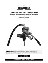
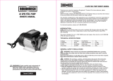
Item #57128
READ & SAVE THESE INSTRUCTIONS
12V Heavy-Duty Fuel Transfer Pump
Gasoline Compatible
Owner’s Manual
WARNING: Read carefully and understand all ASSEMBLY AND OPERATION
INSTRUCTIONS before operating. Failure to follow the safety rules and other basic safety
precautions may result in serious personal injury.

2 of 16
Thank you very much for choosing a Roughneck™ product!
For future reference, please complete the owner’s record below:
Serial Number/Lot Date Code: ________________________________
Purchase Date: ____________________________________________
Save the receipt, warranty, and this manual. It is important that you read
the entire manual to become familiar with this product before you begin
using it.
This fuel transfer pump is designed for certain applications only.
Northern Tool and Equipment is not responsible for issues arising from
modification or improper use of this product such as an application for
which it was not designed. We strongly recommend that this product not
be modified and/or used for any application other than that for which it
was designed.
For technical questions, please call 1-800-222-5381.

3 of 16
Table of Contents
Intended Use .......................................................................................................................................... 4
Packaging Contents .............................................................................................................................. 4
Technical Specifications ...................................................................................................................... 4
Electrical Specifications ....................................................................................................................... 4
Important Safety Information ............................................................................................................... 4
Specific Operation Warnings ............................................................................................................... 6
Main Parts of Product ........................................................................................................................... 8
Assembly Instructions .......................................................................................................................... 8
Before Each Use .................................................................................................................................... 9
Operating Instructions ........................................................................................................................ 10
After Each Use ..................................................................................................................................... 11
Maintenance ........................................................................................................................................ 11
Troubleshooting .................................................................................................................................. 11
Parts Diagram ...................................................................................................................................... 13
Parts List .............................................................................................................................................. 13
Replacement Parts .............................................................................................................................. 14
Limited Warranty ................................................................................................................................. 15

4 of 16
Intended Use
The Roughneck 12V Heavy-Duty Fuel Transfer Pump is a positive displacement, rotary vane pump.
Depending on installation and viscosity, this pump can deliver up to 15GPM or 57 LPM. The rugged
design makes for a long life of dependability.
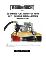
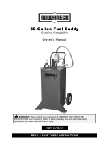
Packaging Contents
Technical Specifications
Inlet: 2" male on tank adapter, 1" female on pump
Outlet: 1" female
Built-in bypass valve
Inlet screen
Thermal overload protection
Furnished with:
14ft x 3/4" hose for 15GPM/57LPM
1 piece steel suction pipe
1 piece auto nozzle.
Class I Division 1 Group D T4
Electrical Specifications
*Using an automatic nozzle and/or filter will reduce the flow rate.
Important Safety Information
⚠WARNING
Read and understand all instructions. Failure to follow all instructions may result in serious injury
No.
Description
Qty.
No.
Description
Qty.
1
Auto Nozzle
1
4
2" Bung Adapter
1
2
Suction pipe
1
5
Elbow
1
3
3/4"x14ft. delivery
hose
1
6
Nozzle Holder
1
Item
Electrical Power
Flow Rate
Nozzle
Current
Voltage
GPM/LPM
#57128
DC
12V
Up to 15/57
*Auto

5 of 16
or property damage.
The warnings, cautions, and instructions in this manual cannot cover all possible conditions or
situations that could occur. Exercise common sense and caution when using this tool. Always be
aware of the environment and ensure that the tool is used in a safe and responsible manner.
Do not allow persons to operate or assemble the product until they have read this manual and
have developed a thorough understanding of how it works.
Do not modify this product in any way. Unauthorized modification may impair the function and/or
safety and could affect the life of the product. There are specific applications for which the product
was designed.
Use the right tool for the job. DO NOT attempt to force small equipment to do the work of larger
industrial equipment. There are certain applications for which this equipment was designed. This
product will be safer and do a better job at the capacity for which it was intended. DO NOT use
this equipment for a purpose for which it was not intended.
Industrial or commercial applications must follow OSHA requirements.
⚠WARNING
WORK AREA SAFETY
Inspect the work area before each use. Keep work area clean, dry, free of clutter, and well-lit.
Cluttered, wet, or dark work areas can result in injury. Using the product in confined work areas
may put you dangerously close to cutting tools and rotating parts.
Do not use the product where there is a risk of causing a fire or an explosion; e.g., in the presence
of flammable liquids, gases, or dust. The product can create sparks, which may ignite the
flammable liquids, gases, or dust.
Do not allow the product to come into contact with an electrical source. The tool is not insulated
and contact will cause electrical shock.
Keep children and bystanders away from the work area while operating the tool. Do not allow
children to handle the product.
Be aware of all power lines, electrical circuits, water pipes, and other mechanical hazards in your
work area. Some of these hazards may be hidden from your view and may cause personal injury
and/or property damage if contacted.
⚠WARNING
PERSONAL SAFETY
Stay alert, watch what you are doing, and use common sense when operating the pump. Do not
use the tool while you are tired or under the influence of drugs, alcohol, or medication. A moment
of inattention while operating the tool may result in serious personal injury.
Dress properly. Do not wear loose clothing, dangling objects, or jewelry. Keep your hair, clothing
and gloves away from moving parts. Loose clothes, jewelry, or long hair can be caught in moving
parts. Air vents on the tool often cover moving parts and should be avoided.
Wear the proper personal protective equipment when necessary. Use ANSI Z87.1 compliant safety

6 of 16
goggles (not safety glasses) with side shields, or when needed, a face shield. Use a dust mask in
dusty work conditions. Also use non-skid safety shoes, hardhat, gloves, dust collection systems,
and hearing protection when appropriate. This applies to all persons in the work area.
Do not overreach. Keep proper footing and balance at all times.
Remove keys or wrenches before connecting the tool to an air supply, power supply, or turning on
the tool. A wrench or key that is left attached to a rotating part of the tool may cause personal
injury.
Secure the work with clamps or a vise instead of your hand when practical. This safety precaution
allows for proper tool operation using both hands.
⚠CAUTION
PUMP USE AND CARE
Do not force the pump. Products are safer and do a better job when used in the manner for which
they are designed. Plan your work, and use the correct product for the job.
Check for damaged parts before each use. Carefully check that the product will operate properly
and perform its intended function. Replace damaged or worn parts immediately. Never operate the
product with a damaged part.
Do not use a product with a malfunctioning switch. Any power tool that cannot be controlled with
the power switch is dangerous and must be repaired by an authorized service representative
before using.
Disconnect the power/air supply from the product and place the switch in the locked or off position
before making any adjustments, changing accessories, or storing the tool. Such preventive safety
measures reduce the risk of starting the tool accidentally.
Store the product when it is not in use. Store it in a dry, secure place out of the reach of children.
Inspect the tool for good working condition prior to storage and before re-use.
Use only accessories that are recommended by the manufacturer for use with your product.
Accessories that may be suitable for one product may create a risk of injury when used with
another tool. Never use an accessory that has a lower operating speed or operating pressure than
the tool itself.
Keep guards in place and in working order. Never operate the product without the guards in place.
Do not leave the tool running unattended.
Specific Operation Warnings
⚠WARNING
To prevent serious injury or property damage, read and understand owner’s manual before
operating.
Know and follow applicable national, state, and local safety codes pertaining to installing and
operating electrical equipment for use with flammable liquids.
Know and follow all safety precautions when handling petroleum fuels.

7 of 16
Ensure that all equipment operators have access to adequate instructions concerning safe
operating and maintenance procedures.
To ensure safe operation, all fuel transfer systems must be properly grounded. Proper grounding
means a continuous metal-to-metal contact from one component to the next, including tank, bung,
pump, meter, filter, hose, and nozzle. Care should be taken to ensure proper grounding during
initial installation and after any service or repair procedures.
To prevent physical injury, observe precautions against fire or explosion when dispensing fuel. Do
not operate the system in the presence of any source of ignition including running or hot engines,
lighted cigarettes, or gas or electric heaters.
Observe precautions against electrical shock when operating the system. Serious or fatal shock
can result from operating electrical equipment in damp or wet locations.
Inspect external pump wiring regularly to make sure it is correctly attached to the battery. To avoid
electrical shock, use extra care when connecting the pump to power.
Avoid prolonged skin contact with petroleum fuels. Use protective goggles, gloves and aprons in
case of splashing or spills. Change saturated clothing and wash skin promptly with soap and
water.
Make sure the power switch is in the off position before connecting power.
Wear the proper protective gear including ANSI Z87.1 compliant safety goggles while operating.
Observe precautions against electrical shock when servicing the pump. Always disconnect power
before repairing or servicing. Never apply electrical power to the system when any of the cover
plates are removed.
If using solvent to clean pump components or tank, observe the solvent manufacturer’s
recommendations for safe use and disposal.
Electrical wiring should be done by a licensed electrician in compliance with local codes. A rigid
conduit should be used and proper grounding must be provided to avoid the possibility of electrical
shock. Failure to comply with this warning could result in serious injury and/or loss of property.
Use only static wire and a conductive hose when pumping flammable fluids.
This product should not be used for fluid transfer into an aircraft. This product is not suited for use
with fluids for human consumption or fluids containing water.
Extreme operating conditions with working cycles longer than 30 minutes can cause the motor
temperature to rise, thus damaging the motor itself. Each 30-minute working cycle should always
be followed by a 30-minute power-off cooling phase.
Use PTFE tape on all pipe threads.
Do not exceed the maximum by-passing time of 3 minutes.
Do not run dry past 30 seconds.
Burn hazard. To reduce the risk of burns, do not touch hot surfaces.
Disconnect circuit before removing cover and enclosure must be closed tightly when circuits are
live.
A seal shall be installed within 50mm of the enclosure.

8 of 16
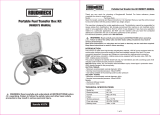
Main Parts of Product
Assembly Instructions
1. Tightly screw the suction pipe into the inlet coupling of the pumping unit. Extend the suction pipe
into the truck tank or barrel to within 3" of the tank’s bottom.
2. Screw the inlet coupling of the pump into 2" of the tank or barrel opening. The inlet coupling must
be completely and securely threaded into an undamaged tank or barrel bung.
3. During installation and maintenance, make sure that the electric supply lines are not live.
4. Always turn off the switch before supplying electrical power.
5. Check the correct rotation direction of the DC pump. If it is inverted, check the polarity of the
connection cable.
a) BLACK cable: positive pole (+)
b) WHITE cable: negative pole (-)
6. Systems should be designed to require a minimum amount of suction lift. Maximum “equivalent
feet of lift” is 8’ for diesel fuel.
7. The tank or barrel must be properly vented. A water separator should be used for pumping diesel
fuel.
8. DC Electrical

9 of 16
8.1 Remove the pump’s junction box cover and straighten the two wires to make the stripped
wire ends accessible outside of the junction box.
8.2 Screw furnished cable connector into 1/2" NPT conduit opening in pump junction box.
8.3 Strip 6" of the outer covering from one end of the furnished electrical cable being careful not
to damage the black and red wire insulation.
8.4 Loosen the cable connector nut and pass the stripped end of the furnished cable through
the cable connector until 2" of the unstrapped cable is within the cable connector. Tighten the
cable connector nut.
8.5 Strip 1/2" of the installation from the ends of the red and black cable wires. Using the
furnished wire nuts, connect these wires to the pump wires matching the colors. Be sure bare
wire is NOT exposed.
8.6 Fold wires into the junction box and replace the cover making sure the gasket is in place.
Make sure all screws are seated so there is no space between the cover and the junction box.
Before Each Use
⚠WARNING
To prevent serious injury or property damage, read and understand owner’s manual before
operating.
Know and follow applicable national, state, and local safety codes pertaining to installing and
operating electrical equipment for use with flammable liquids.
Know and follow all safety precautions when handling petroleum fuels.
Ensure that all equipment operators have access to adequate instructions concerning safe
operating and maintenance procedures.
To ensure safe operation, all fuel transfer systems must be properly grounded. Proper grounding
means a continuous metal-to-metal contact from one component to the next, including tank, bung,
pump, meter, filter, hose, and nozzle. Care should be taken to ensure proper grounding during
initial installation and after any service or repair procedures.
To prevent physical injury, observe precautions against fire or explosion when dispensing fuel. Do
not operate the system in the presence of any source of ignition including running or hot engines,
lighted cigarettes, or gas or electric heaters.
Observe precautions against electrical shock when operating the system. Serious or fatal shock
can result from operating electrical equipment in damp or wet locations.
Make sure the power switch is in the off position before connecting power.
Wear the proper protective gear including ANSI Z87.1 compliant safety goggles while operating.
Observe precautions against electrical shock when servicing the pump. Always disconnect power
before repairing or servicing. Never apply electrical power to the system when any of the cover
plates are removed.
Disconnect circuit before removing cover and enclosure must be closed tightly when circuits are
live.

10 of 16
Operating Instructions
⚠WARNING
Know and follow applicable national, state, and local safety codes pertaining to installing and
operating electrical equipment for use with flammable liquids.
Know and follow all safety precautions when handling petroleum fuels.
Ensure that all equipment operators have access to adequate instructions concerning safe
operating and maintenance procedures.
To ensure safe operation, all fuel transfer systems must be properly grounded. Proper grounding
means a continuous metal-to-metal contact from one component to the next, including tank, bung,
pump, meter, filter, hose, and nozzle. Care should be taken to ensure proper grounding during
initial installation and after any service or repair procedures.
To prevent physical injury, observe precautions against fire or explosion when dispensing fuel. Do
not operate the system in the presence of any source of ignition including running or hot engines,
lighted cigarettes, or gas or electric heaters.
Observe precautions against electrical shock when operating the system. Serious or fatal shock
can result from operating electrical equipment in damp or wet locations.
Inspect external pump wiring regularly to make sure it is correctly attached to the battery. To avoid
electrical shock, use extra care when connecting the pump to power.
Avoid prolonged skin contact with petroleum fuels. Use protective goggles, gloves and aprons in
case of splashing or spills. Change saturated clothing and wash skin promptly with soap and
water.
Wear the proper protective gear including ANSI Z87.1 compliant safety goggles while operating.
This product should not be used for fluid transfer into an aircraft. This product is not suited for use
with fluids for human consumption or fluids containing water.
Extreme operating conditions with working cycles longer than 30 minutes can cause the motor
temperature to rise, thus damaging the motor itself. Each 30-minute working cycle should always
be followed by a 30-minute power-off cooling phase.
Use PTFE tape on all pipe threads.
Do not exceed the maximum by-passing time of 3 minutes.
Do not run dry past 30 seconds.
Burn hazard. To reduce the risk of burns, do not touch hot surfaces.
Operating Conditions
Temperature: Min. -68°F Max.104°F (Min.-20°C Max. +40°C)
Relative Humidity: max 90%
Fluid Compatibility
These products are compatible with the following fluids:
Gasoline, Diesel, Kerosene, and Mineral Spirits
⚠CAUTION
Do NOT use with other fluids without consulting manufacturer.

11 of 16
If using flexible tubing, attach the ends of the tubing to the tanks. In the absence of an
appropriate slot, solidly grasp the delivery tube before beginning dispensing.
Before starting the pump make sure that the delivery valve is closed (dispensing nozzle or line
valve).
Turn the ON/OFF switch to ON. The by-pass valve allows functioning with the delivery closed for
only brief periods.
Open the delivery valve, solidly grasping the end of the tubing.
Close the delivery valve to stop dispensing.
When dispensing is finished, turn off the pump.
After Each Use
⚠WARNING
If using solvent to clean pump components or tank, observe the solvent manufacturer’s
recommendations for safe use and disposal.
Burn hazard. To reduce the risk of burns, do not touch hot surfaces.
Store the product when it is not in use. Store it in a dry, secure place out of the reach of children.
Inspect the tool for good working condition prior to storage and before re-use.
Maintenance
Maintain the product by adopting a program of conscientious repair and maintenance in accordance
with the following recommended procedures. It is recommended that the general condition of any tool
be examined before it is used. Keep your tool in good repair. Keep handles dry, clean, and free from
oil and grease. Also refer to the engine manufacturer’s instruction manual for additional information
about engine maintenance. The following chart is based on a normal operation schedule.
Maintenance Interval
Maintenance Point
Daily operating
Under normal working conditions the noise emission from all
models does not exceed the value of 80 db at a distance of 1
meter from the electric pump.
Troubleshooting
Use the table below to troubleshoot problems before contacting service personnel or your local
dealer. If the problem continues after troubleshooting, call your local dealer for assistance.
Problem
Possible Cause
Corrective Action
The motor is not turning
Lack of electric power
Check the electrical connections and
the safety systems
Rotor jams
Check for possible damage or
obstruction of the rotating
components.

12 of 16
Problem
Possible Cause
Corrective Action
Motor problems
Contact with the service department
Thermal overload protection
shut-down
Move ON/OFF lever to the OFF
position to reset pump.
Low or no flow rate
Low level in the suction tank
Refill the tank
Foot valve blocked
Clean and/or replace the valve
Filter clogged
Clean the filter
Excessive suction pressure
Lower the pump with respect to the
level.
High loss of head in the circuit
(working with the by-pass open)
Use shorter tubing or of greater
diameter
By-pass valve blocked
Dismantle the valve, clean and/or
replace it
Air entering the pump or the
suction tubing
Check the seals of the connections
A narrowing in the suction tubing
Use tubing suitable for working under
suction pressure
Low rotation speed
Check the voltage at the pump.
Adjust the voltage and/or use cables
of greater cross-section
The suction tubing is resting on
the bottom of the tank
Raise the tubing
Increased pump noise
Cavitations occurring
Reduce suction pressure
Irregular functioning of the by-
pass
Dispense until the air is purged from
the circuit
Air present in the diesel fuel
Verify the suction connections
Leakage from the pump
body
Seal damaged
Check and replace the mechanical
seal

13 of 16
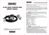
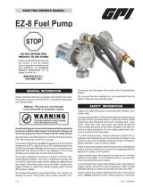
Parts Diagram
Parts List
No.
Description
Qty.
No.
Description
Qty.
1
Screw
6
20
Screw
2
2
Rotor cover
1
21
Switch
1
3
Rotor
1
22
Bracket
1
4
Vane
5
23
Bushing
1
5
Spring
5
24
Gasket
1
6
O-ring
1
25
Nut
1
7
Gasket
1
26
Seal
1
8
Seal Kit
1
27
Shift folk
1
9
Discharge hose
1
28
O-ring
1
10
Elbow
1
29
Junction box cover
1
11
Bypass spring
1
30
Screw
6

14 of 16
No.
Description
Qty.
No.
Description
Qty.
12
Electric motor
1
31
Grounded screw
1
13
Pump chamber
1
32
Switch bracket
1
14
Bypass valve
1
33
Nozzle holder
1
15
O-ring
1
34
Auto Nozzle
1
16
Filter screen
1
35
Screw
2
17
2” Bung adapter
1
18
Screw
2
19
Suction tube
1
Replacement Parts
For replacement parts and technical questions, please call Customer Service at 1-800-222-5381.
Not all product components are available for replacement. The illustrations provided are a
convenient reference to the location and position of parts in the assembly sequence.
When ordering parts, the following information will be required: item description, item model
number, item serial number/item lot date code, and the replacement part reference number.
The distributor reserves the rights to make design changes and improvements to product lines
and manuals without notice.

15 of 16
Limited Warranty
Northern Tool and Equipment Company, Inc. ("We'' or "Us'') warrants to the original purchaser only
("You'' or "Your") that the Roughneck product purchased will be free from material defects in both
materials and workmanship, normal wear and tear excepted, for a period of one year from date of
purchase. The foregoing warranty is valid only if the installation and use of the product is strictly in
accordance with product instructions. There are no other warranties, express or implied, including the
warranty of merchantability or fitness for a particular purpose. If the product does not comply with this
limited warranty, Your sole and exclusive remedy is that We will, at our sole option and within a
commercially reasonable time, either replace the product or product component without charge to You
or refund the purchase price (less shipping). This limited warranty is not transferable.
Limitations on the Warranty
This limited warranty does not cover: (a) normal wear and tear; (b) damage through abuse, neglect,
misuse, or as a result of any accident or in any other manner; (c) damage from misapplication,
overloading, or improper installation; (d) improper maintenance and repair; and (e) product alteration
in any manner by anyone other than Us, with the sole exception of alterations made pursuant to
product instructions and in a workmanlike manner.
Obligations of Purchaser
You must retain Your product purchase receipt to verify date of purchase and that You are the original
purchaser. To make a warranty claim, contact Us at 1-800-222-5381, identify the product by make
and model number, and follow the claim instructions that will be provided. The product and the
purchase receipt must be provided to Us in order to process Your warranty claim. Any returned
product that is replaced or refunded by Us becomes our property. You will be responsible for return
shipping costs or costs related to Your return visit to a retail store.
Remedy Limits
Product replacement or a refund of the purchase price is Your sole remedy under this limited warranty
or any other warranty related to the product. We shall not be liable for: service or labor charges or
damage to Your property incurred in removing or replacing the product; any damages, including,
without limitation, damages to tangible personal property or personal injury, related to Your improper
use, installation, or maintenance of the product or product component; or any indirect, incidental or
consequential damages of any kind for any reason.
Assumption of Risk
You acknowledge and agree that any use of the product for any purpose other than the specified
use(s) stated in the product instructions is at Your own risk.
Governing Law
This limited warranty gives You specific legal rights, and You also may have other rights which vary
from state to state. Some states do not allow limitations or exclusions on implied warranties or
incidental or consequential damages, so the above limitations may not apply to You. This limited
warranty is governed by the laws of the State of Minnesota, without regard to rules pertaining to
conflicts of law. The state courts located in Dakota County, Minnesota shall have exclusive jurisdiction
for any disputes relating to this warranty.

16 of 16
Distributed by:
Northern Tool & Equipment Company, Inc.
Burnsville, Minnesota 55306
www.northerntool.com
Made in China
/