Fill-rite NX25-DDCNF-PX Operating instructions

Type
Operating instructions

This manual is also suitable for

The Fill-rite NX25-DDCNF-PX is a heavy-duty DC fuel transfer pump designed for continuous duty cycles, making it ideal for transferring large volumes of fuel. With its intelligent microprocessor, the pump automatically adjusts its RPM to optimize performance and features an automatic shut-off if left running in bypass mode for 20 minutes, preventing unnecessary wear and battery drain. The pump also includes a variety of safety features, including protection from thermal overload and an anti-siphon device.

The Fill-rite NX25-DDCNF-PX is a heavy-duty DC fuel transfer pump designed for continuous duty cycles, making it ideal for transferring large volumes of fuel. With its intelligent microprocessor, the pump automatically adjusts its RPM to optimize performance and features an automatic shut-off if left running in bypass mode for 20 minutes, preventing unnecessary wear and battery drain. The pump also includes a variety of safety features, including protection from thermal overload and an anti-siphon device.

MADE IN
USA
NX25-DDC SERIES DC FUEL TRANSFER PUMPS
Installation and Operation Manual
This manual contains English language only. Visit www.fillrite.com to
download more languages.
| NX25-DDC SERIES DC FUEL TRANSFER PUMP
Table of Contents
Limited Warranty Policy
Revision Date: August 1, 2014
Fill-Rite and Sotera Products
Tuthill Transfer Systems ("Manufacturer") warrants each consumer buyer of its products ("Buyer") from date of sale that goods of its manufacture ("Goods") shall be free
from defects of materials and workmanship.
The duration of the warranty is as follows:
* Proof of purchase should be presented to place of purchase
End users must contact the place where they purchased the product to process a warranty. “Place of purchase” is defined as any authorized Tuthill Transfer Systems
Distributor, including any and all retail stores, mail order houses, catalogue houses, on-line stores, commercial distributors.
Manufacturer’s sole obligation under the foregoing warranties will be limited to either – at Manufacturers option – replacing defective goods (subject to limitations
hereinafter provided) or refunding the purchase price for such Goods theretofore paid by the buyer, and Buyers exclusive remedy for breach of any such warranties will
be enforcement of such obligations of the Manufacturer. If the Manufacturer so requests the return of such Goods, the Goods will be redelivered to the manufacturer in
accordance with Manufacturer’s instructions FOB Factory.
The remedies contained herein shall constitute the sole recourse of the Buyer against the Manufacturer for breach of warranty. IN NO EVENT SHALL THE
MANUFACTURER'S LIABILITY FOR ANY CLAIM FOR DAMAGES ARISING OUT OF THE MANUFACTURE, SALE, DELIVERY, OR USE OF THE GOODS EXCEED
THE PURCHASE PRICE.
The foregoing warranties will not extend to goods subject to misuse, neglect, accident, improper installation or maintenance, or have been repaired
by anyone other than the Manufacturer or its authorized representative. THE FOREGOING WARRANTIES ARE EXCLUSIVE AND IN LIEU OF ALL OTHER
WARRANTIES OF MERCHANTABILITY, FITNESS FOR PURPOSE OF ANY OTHER TYPE, WHETHER EXPRESSED OR IMPLIED. No person may vary the
forgoing warranties or remedies, except in writing signed by a duly authorized officer of the Manufacturer. The Buyer's acceptance of delivery of the Goods
constitutes acceptance of the foregoing warranties and remedies, and all conditions and limitations thereof.
From Date of Sale Not to Exceed the Following Period from Date of Manufacture Product Series
Five (5) Years 60 Months 400 Series Pumps
Two (2) Years 27 Months
Heavy Duty Pumps and Meters, 820, 825,
850 Meters, and NX Series Pumps
Cabinet Pumps, Cabinet Meters,
TN Meters, TM Meters, TS Meters
One (1) Year 15 Months
Standard Duty Pumps and Meters,
1600 Pumps
Accessories
Parts
Unique nextec Features ........................................................ 3
Safety Information
............................................................... 3
Fueling Safety
...................................................................... 4
Installation
........................................................................... 4
Nozzle Boot Installation
....................................................... 5
Pump Foot Installation
......................................................... 5
Anti-Siphon Device .............................................................. 6
Tank Installation
.................................................................. 6
DC Power Connection
.......................................................... 7
Padlocking
.......................................................................... 7
Operational Safety
............................................................... 8
Operating Instructions
......................................................... 8
Dimensional Information
..................................................... 9
Technical Information
........................................................10
Accessories
.........................................................................10
Servicing the Bypass Valve
.................................................11
Replacement Parts Information
......................................... 12
Servicing Rotor, Vanes and Shaft Seals
............................. 12
Exploded View
.................................................................... 13
Troubleshooting
...................................................................14
Intelligent Tones
..................................................................15
Safety Testing Certifications
..............................................16
Thank You!
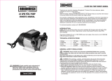
Thank you for your purchase of the Fill-Rite
®
NX25-DDC. Your Fill-Rite
product comes with decades of pump manufacturing experience behind
it, providing you the value that comes with superior performance, user
friendly design, outstanding durability, and solid, simple engineering.
Tuthill Pump Your Heart Into It.
3
fillrite.com | tuthill.com
INSTALLATION AND OPERATION MANUAL
Unique Features of the nextec Pump
Your nextec fuel transfer pump will perform differently from non-intelligent pumps on start-up and while operating. You will want to keep the following in mind as you begin
to use and learn how your nextec Intelligence™ pump operates.
On initial start up, the pump may rev momentarily, but will slow down, as if idling, as it reponds to the load it senses. This is a normal condition, and it will continue
at this low speed until you squeeze the handle on the dispensing nozzle to begin fluid flow.
When you squeeze the nozzle handle to begin flow, the microprocessor in the pump will sense the change, and will raise the RPM’s to meet the load.
It is not uncommon for the pump to change RPMs during operation. It will do this as it senses performance parameters are changing; for example, if you increase or
decrease the flow at the nozzle, the electronics controlling the motor will sense the changes and adjust the motor speed to optimize performance.
If the pump senses a condition that is outside normal operating parameters (low battery voltage, for example), it will sound a series of tones to alert you to the
condition, and to help you diagnose it. See the “Intelligent Tones” section of the Troubleshooting Guide on page 14 for greater detail on this feature.
Your NX25-DDC pump has a Continuous Duty Cycle, meaning it does not have to be shut off to “rest” after a specific period of use. This allows you to move from
fueling one piece of equipment to another without having to shut the pump off. The nextec Intelligence does, however, have an automatic shut off if the pump is left
running in bypass mode (without dispensing any fluid) for 20 minutes. This features protects from excessive battery drain, as well as excessive uneccessary wear
to the pump in the event you forget to shut the pump off. Should the pump turn itself off under these conditions, simply cycle the power switch off, then back on to
restore pump operation.
The nextec Intelligence will also shut the motor down if:
Pump temperature exceeds threshold parameters
Supply voltage is outside threshold parameters
Rotor is locked
About This Manual
From initial concept and design through its final production, your Fill-Rite pump is built to give you years of trouble-free use. To ensure it provides that service, and to avoid
injury or death, it is critical that you read this entire manual prior to attempting to install or operate your new pump. Become familiar with the terms and diagrams, and pay
close attention to the highlighted areas with the following labels:
CAUTION! Failure to observe a “Caution” may cause damage to the
equipment.
At Tuthill, your satisfaction with our products is paramount to us. If you have questions or need assistance with your product, please contact us at 1-800-634-2695
(M-F 8 AM6 PM ET).
Safety Information
DANGER! Electrical wiring should be performed with extreme caution and in compliance with local, state, and national electrical code NEC/ANSI/NFPA 70, NFPA 30,
and NFPA 30A, as appropriate for the intended use of the pump. Threaded rigid conduit, sealed fittings, and conductor seal should be used where applicable. The
pump must be properly grounded. If installing in deviation of this manual, a licensed electrician must perform the installation. Improper installation or use of this
product will result in serious bodily injury or death!
DANGER! To ensure safe and proper operation of your equipment, it is critical to read and adhere to all of the following safety warnings and precautions. Failure to
follow instructions below, improper installation, or use of this product, will cause serious bodily injury or death!
NEVER smoke near the pump, or use the pump near open flames when pumping a flammable liquid! Fire can result!
This product shall not be used to transfer fluids into any type of aircraft.
DANGER! To minimize static electricity build up and possible explosion, use only static wire conductive hose when pumping flammable fluids, and keep the fill nozzle
in contact with the container being filled during the filling process. Spark / static discharge will cause explosions.
WARNING! Threaded pipe joints and connections should be sealed with the appropriate sealant or sealant tape to minimize the possibility of leaks. Leaking fuel may cause the
potential for fire and explosion.
CAUTION! The pump motor is equipped with electronic protection from thermal overload; if overheated, the motor will shut off. After the motor has cooled, you may cycle power
or the switch to reset this safety feature and continue use. The pump will not restart until properly cooled.
WARNING!
Emphasizes an area in which personal injury or even death may result from
failure to follow instructions properly. Mechanical damage may also occur.
IMPORTANT!
These boxes contain information that illustrates
a point that may save time, or be key to proper operation, or clarifies a step.
DANGER!
Emphasizes an area in which personal injury or even death will result from
failure to follow instructions properly. Mechanical damage may also occur.
| NX25-DDC SERIES DC FUEL TRANSFER PUMP
As a tank is being filled, air is displaced and exits via the fuel tank
vent creating fumes, which when accumulated create an Explosive
Atmosphere. To avoid possible explosion of accumulated vapors, it is
critical to keep possible sources of spark / ignition at safe distances
from the fuel vapors.
The accompanying diagram shows minimum safe distances for safe
fueling. 10’ is the minimum safe distance between:
Power source and fuel supply
Power source and tank being filled
Power source and pump
Fueling Safety
Installation
Your Fill-Rite NX25-DDC pump is designed to be mobile for your convenience and safety. It can be installed / used in several configurations. Read each configuration
prior to beginning installation.
CAUTION! This product is not suited for use with fluids intended for human consumption or fluids containing water. Materials of construction are not food grade. Water
will cause rust and corrosion in the pump housing. If water enters the pump, flush immediately with a petroleum product (gasoline, diesel, light oil, etc) to eradicate
residual water.
IMPORTANT! A Fill-Rite filter should be used on the pump outlet to ensure no foreign material is transferred to the fuel tank. Foreign material can damage the
equipment being fueled.
WARNING! The NX25-DDC smart pump is designed for use on skid tanks, and large bulk tanks to supply fuel. It is paramount to anchor the supply tank to which the pump
is mounted to ensure no movement occurs in transit or while fueling. Failure to secure the tank or drum can cause unexpected and uncontrolled movement, resulting in
damage, injury, death, and potential fire or explosion.
DANGER! Fumes accumulated while fueling create an Explosive Atmosphere. It is CRITICAL that all possible sources of ignition be removed to a safe distance or
extinguished. Sources of ignition would include (but not be limited to) open flames, cigarettes, static discharge, or electrical connections that can create a spark.
Explosion, fire, and severe injury or death will occur if the explosive vapors are ignited.
SUCTION TUBE OR HOSE DISCHARGE HOSE
PUMP
POWER SUPPLY
POWERCORD
If applicable.
PUMP INLET
SIDE TANK
PUMP OUTLET
SIDE TANK
10' MIN 10' MIN
10' MIN
.
.
.
.
5
fillrite.com | tuthill.com
INSTALLATION AND OPERATION MANUAL
IMPORTANT! Do not use check valves or foot valves; valves reduce rate of flow and performance of the pump.
Nozzle Boot Installation
Mounting peg
Mounting bolt
Pump Foot Installation
Install the nozzle boot using the supplied attaching bolt. Note that the bolt is
inserted through the hole closest to the nozzle opening, and the boot is then
positioned so the peg on the pump mounting surface inserts in the top second
hole of the boot. This allows for correct alignment of the nozzle when inserted into
the boot.
The mounting foot is bolted to the bottom of the pump using
the four supplied socket head cap screws. Mount the foot
with the bolt flanges inboard of the mounts on the pump as
illustrated. Torque to 50 in lb. with 4 mm hex key.
| NX25-DDC SERIES DC FUEL TRANSFER PUMP
Materials:
1-1/4” steel pipe cut to a length at least 3” above of the bottom of the tank when screwed
into the tank adapter, with the tank adapter screwed into the bung conection on top of the
tank.
Thread pipe joint sealant appropriate for the application.
1. Thread the 1-1/4” pipe into the tank adapter. Seal threads liquid tight with appropriate sealant (Figure 1).
2. Screw the tank adapter (with suction pipe) into the tank bung; seal threads liquid tight with appropriate thread sealant (Figure 2).
3. Mount the pump on the adapter; making sure the seal and screen are installed as shown (Figure 3).
Tank Installation
The NX25-DDC pump mounts to the bung of a tank by way of the tank adapter that is bolted to the inlet flange. The suction tube threads into the bottom of the tank
adapter, and must be cut to a length that positions it at least 3” from the bottom of the tank. The tank must be equipped with a vent cap.
Figure 2
Figure 3
Figure 1
TYPICAL TANK INSTALLATION
3" Min.
IMPORTANT! Be certain the screen is properly seated in the indentation in the tank adapter before installing seal and tank adapter to the pump. Failure to properly
seat the screen can result in fluid leakage.
Anti-Siphon Device
NX25-DDC pumps come from the factory ready to install an anti-siphon tube back
to the tank. An anti-siphon device (a.k.a. vacuum breaker) is important because it
will break a liquid siphon if there is an open nozzle or a leaking hose below the fluid
level in the tank when the pump is turned off. Fill-Rite recommends anti-siphon kit #
KIT321ASN be installed from the pump outlet back to the vapor space in the tank.
This illustration shows where to install the tube so that it terminates in the vapor space
at the top of the tank. The tube must terminate in the vapor space; if it terminates
below the fluid level in the tank, it will not prevent siphoning. It is very important there
are no liquid traps in the tubing; it must have a continuous slope from the pump down
to the tank, and can be connected into any opening in the top of the tank if the tank
adapter is not used. Use reducer bushings as required for proper fit and seal.
The ¼ NPT opening in the side of the tank adapter terminates in the vapor space of the
tank. Make liquid-tight connections using the appropriate sealant from the adapter
to the anti-siphon outlet using a minimum of ¼ metal tubing that is compatible with
whatever liquid is being pumped. If the anti-siphon tank adapter is being used and the
¼ NPT opening is not used for the tubing, leave the factory installed plug in place.
Fill-Rite offers Anti-Siphon kit # KIT321ASN (available through your Fill-Rite
distributor). This kit contains the necessary fittings and tubing to complete the
installation as pictured in this section. NOTE: This kit ONLY works for tank top
installations.
ANTI-SIPHON INSTALLATION
Anti-Siphon Line
7
fillrite.com | tuthill.com
INSTALLATION AND OPERATION MANUAL
Inspect power cable before each use! Damage to the outer jacket of the cable
that exposes wiring requires replacement of the power cable.
1. The green (ground) wire should be connected first. Connect the green wire
to the vehicle chassis or earth ground. DO NOT connect the green wire to
the negative power source post.
2. Next, connect the black (negative) wire to the negative post of the DC
power source.
3. Connect the red (positive) wire to the positive post last.
Install power cable by aligning flat on plug with back of pump. Insert the plug
into the motor housing as shown. Lock into place using the threaded collar (A).
HAND TIGHTEN ONLY!
Disconnect in reverse order.
DC Power Connection
Earth /
Chassis
Ground
Green
RedBlack
A
Flat
1
2 3
DANGER! Be certain the switch is “OFF” prior to connecting the power cables to the power source or installing the cable into the pump to prevent unexpected starting
of the motor. Unexpected motor start can cause unintended discharge of fuel, creating an explosion and fire hazard. Note that the switch does not interrupt power to the
motor; it triggers a relay that tells the motor to turn on.
WARNING! BE CERTAIN the power cables are connected to the correct terminals at your power source. REVERSING POLARITY WILL DAMAGE THE PUMP and void the
warranty.
CAUTION! Do not remove the fuse on the red (positive) wire. Removing
the fuse MAY DAMAGE THE PUMP and will void the warranty.
Padlocking
Your Fill-Rite pump nozzle can be padlocked to the pump for added security. With the
pump turned off, and the nozzle in the stored position, a padlock can be inserted through
the locking link and the nozzle handle opening. This configuration prevents the nozzle from
being removed from the nozzle boot.
The locking link is located on the nozzle side of the pump, and can be pivoted into position to
work with a variety of nozzles.
Use the appropriate position and hole to lock your nozzle securely to your NX25-DDC pump.
Locking Link
| NX25-DDC SERIES DC FUEL TRANSFER PUMP
Operating Instructions
1. If so equipped, reset Meter to “0” (do not reset while in use as this can cause damage to the meter).
2. Remove dispensing nozzle from nozzle boot.
3. Move the switch lever to the “ON” (raised) position to start the motor (Figure 5). The pump should start and settle into a slow idle.
4. Insert the dispensing nozzle into the container to be filled.
5. Operate the nozzle to dispense fluid; release nozzle when the desired amount of fluid has been dispensed.
6. Move switch lever to the “OFF” (lowered) position (Figure 6) to stop the motor.
7. Remove the dispensing nozzle from the container being filled and store it in the nozzle boot.
Operational Safety
Figure 6
Switch “OFF
Figure 5
Switch “ON”
DANGER! DO NOT use pump in enclosed areas when pumping hazardous or explosive fluids. Pumping area should be well ventilated. Concentrated vapors in an enclosed
area are noxious and highly explosive!
WARNING! NEVER disconnect the power cable from the pump while pump is switched on or connected to a power source. ALWAYS switch the pump off and disconnect all
the clamps from the power source PRIOR to disconnecting the power cable from the pump. Electrical shorts, sparks, or unexpected start up can occur.
WARNING! Use caution when operating the pump. The hoses and electrical power cable can be a trip hazard; caution should be exercised while moving around the hoses
and power cable connected to avoid tripping or entanglement.
WARNING! Pump assembly can become hot with extended use. Use caution if you have to touch the pump after extended periods of use.
CAUTION! Always keep the nozzle in contact with the container being filled during the filling process to minimize the possibility of static electricity build up.
IMPORTANT! The motor has power at all times when connected to a power source. The switch does not apply or interrupt power to the motor. High voltage may still be
present inside the pump after power is removed.
9
fillrite.com | tuthill.com
INSTALLATION AND OPERATION MANUAL
NX25-DDC Dimensional Information
Bung Mount Dimensional Information
Foot Mount Dimensional Information
All measurements are in inches [millimeters].
| NX25-DDC SERIES DC FUEL TRANSFER PUMP
Motor Specification
Power - DC 12, 24, 12/24 12 - 24 VDC
HP (horsepower) rating 1/3 HP
Power cable length 20’
Power cable gauge 10 AWG
Power cable DC battery connectors Yes
Amps (MAX) 30 - 15 Amp
RPM Variable 400 - 3500
Duty cycle Continuous
Thermal protection Electronically Protected
Circuit protection fuse Yes (35 Amp Fuse)
Certification UL/cUL listed/CE/ATEX/IECEx/EAC
Pump
Design Positive Displacement Rotary Vane
Flow rate (with supplied hose / nozzle) Up to 25 GPM / 95 LPM
Flow rate open flow - no hose or nozzle Up to 28 GPM / 106 LPM
Max discharge pressure 21 PSI
Dry vac (in Hg) 11 in vacuum
Head – Max (ft) 48’
Anti-siphon valve None
Inlet – size / thread 1-1/4” NPT / BSPP
Outlet – size / thread 1” NPT / BSPP
Mount 2” Bung NPT or BSPT
Materials of construction – pump housing Cast Iron
Materials of construction – wetted material BUNA-N + Fluorocarbon
Rotor materials of construction Powdered Iron
Rotor vane material of construction Acetal
Compatible fluids Diesel, Gasoline, BioDiesel up
to B20, E15, Kerosene, Mineral
Spirits, Methanol (up to 15%)
Strainer mesh size 20 x 20
Warranty (yr) 2 Year
Maximum sound level 75.3 dB
Technical Information Accessories
Accessories Description
N100DAU13 1" Ultra Hi Flow Automatic Nozzle
N100DAU12G 1“ Hi-Flow Automatic Nozzle (Diesel)
N100DAU13G 1" Ultra Hi-Flow Automatic Nozzle (Diesel)
N100DAU12 1" Hi Flow Automatic Nozzle
900CD Digital Meter
900CDP Digital Meter with Pulser
FRH10020 20' x 1" Static Discharge Hose
FRH10012 12' x 1" Static Discharge Hose
S100H1315 1" Multi Plane Swivel
TT10AN 1" Digital In-Line Turbine Meter
700ACCF7017 1" Filter Head
F4010PM0 10 Micron Filter
F4030PM0 30 Miron Filter
11
fillrite.com | tuthill.com
INSTALLATION AND OPERATION MANUAL
WARNING! Disconnect electrical power and relieve any pressure in the lines prior to servicing this pump! Failure to do so can result in damage to the equipment and
personal injury or death!
IMPORTANT! Removal of the bypass valve in the NX25-DDC pump requires special attention; please adhere to the replacement procedure in the kit instructions to
minimize the possibility of damaging the pump housing during the removal and reinstallation process. Kit instructions accompany all purchased kits.
WARNING! Always wear eye protection anytime you look into the Pump Outlet; a miss-positioned or improperly installed valve spring retainer can pop up unexpectedly.
Note that use of a small flashlight will help you better see and more easily align the components in this task.
WARNING! It is critical that the locking tab be seated in the indentation in the bypass valve retainer as illustrated. Failure to do so can cause the Retainer to come off
when operating in bypass mode, potentially damaging the pump, or ejecting upward through the pump outlet while servicing.
Servicing the Bypass Valve (Dis-assembly)
1. Using needle nose pliers, place the bypass valve retainer on top of the bypass valve spring. Carefully align the slot in the top of the bypass valve retainer with
the locking tab on top of the bypass valve (Figure 4).
2. Push the bypass valve retainer down over the locking tab on the bypass valve. Push the retainer down (compressing the spring) until it is completely below the
locking tab (Figure 5).
3. Rotate the bypass valve retainer 90 degrees counter-clockwise and allow the spring to gently push it back up to contact the locking tab. The locking tab MUST
be seated in the indentation in the bypass valve retainer (Figure 6).
Servicing the Bypass Valve (Re-assembly)
The bypass valve is located inside the pump
housing. It is accessed through the inlet and outlet
openings.
It consists of three main components (Figure 1):
A. Bypass Valve Retainer
B. Bypass Valve Spring
C. Bypass Valve
1. Unbolt the pump from the tank adapter.
2. Using a blunt object approximately 4" long (i.e. a deep well socket on an extension) inserted in the inlet
opening, push the bypass valve firmly in place against the seat it seals on (Figure 2).
3. While holding the bypass valve firmly in place with the socket, insert needle nose pliers (at least 4" long)
into the outlet opening and grasp the bypass valve retainer (Figure 2 & 3).
4. Push the bypass valve retainer down slightly and rotate it 90 degrees counter-clockwise. This will align
the slot in the retainer with the key on the valve, allowing you to remove the retainer (Figure 2 & 3).
Figure 1
A
B
C
Figure 3
Figure 5 Figure 6
Figure 4
Figure 2
| NX25-DDC SERIES DC FUEL TRANSFER PUMP
KIT321RK - Overhaul repair kit KIT321BV - Bypass kit KIT321BG - Inlet kit
R
ITEM NO.
PART NUMBER
DESCRIPTION
QTY.
1
SA001885-000
ASSEMBLY; MOTOR SWITCH
1
2
FS001881-000
LHSHCS; M6 X 1.0 X 14MM
2
3
700F2950
LOCK NUT, 5/16-18
1
4
MF000507-001
LEVER; SWITCH
1
kit321sw
PART NUMBER
MUST BE RoHS COMPLIANT
NOTICE
DIMENSIONS ARE IN INCHES
THIS DRAWING AND THE PRINCIPLES AND ELEMENTS OF DESIGN
EMBODIED THEREIN ARE THE EXCLUSIVE PROPERTY OF
TUTHILL CORPORATION, TUTHILL TRANSFER SYSTEMS
AND ARE NOT TO
BE COMMUNICATED, DISCLOSED, REPRODUCED OR USED EXCEPT AS PREVIOUSLY
AUTHORIZED IN WRITING BY SAID COMPANY AND MUST NOT BE SUBMITTED TO
OUTSIDE PARTIES FOR EXAMINATION WITHOUT THE CONSENT OF SAID COMPANY
PART NUMBER
kit321sw
DWN
MATERIAL
ECN NUMBER
DATE
REV
0.01in
0.005in
0.0005in
0.5°
64 µ" AA MAX
PER PART PRINTS
KIT, NX3200 SERIES SWITCH ASSEMBLY
SHEET
1 OF 1
THIRD ANGLE
PROJECTION USED
DATE
0 011248
01/05/16
UNLESS OTHERWISE SPECIFIED
TWO PLACE DECIMAL
THREE PLACE DECIMAL
FOUR PLACE DECIMAL
ANGULAR
MACHINED SURFACE FINISH
DENOTES DIMENSION CRITICAL TO QUALITY
C
SCS
9/15/2017
R
ITEM NO.
PART NUMBER
DESCRIPTION
OFF/QTY.
1
SHIPPING ENVELOPE
1
2
SL000843-000
O-RING, BUNA-N, 2-036
1
3
100F0790
GASKET, INLET FLANGE
1
4
100F0760
INLET SCREEN
1
KIT321SK
PART NUMBER
MUST BE RoHS COMPLIANT
NOTICE
DIMENSIONS ARE IN INCHES
THIS DRAWING AND THE PRINCIPLES AND ELEMENTS OF DESIGN
EMBODIED THEREIN ARE THE EXCLUSIVE PROPERTY OF
TUTHILL CORPORATION, TUTHILL TRANSFER SYSTEMS
AND ARE NOT TO
BE COMMUNICATED, DISCLOSED, REPRODUCED OR USED EXCEPT AS PREVIOUSLY
AUTHORIZED IN WRITING BY SAID COMPANY AND MUST NOT BE SUBMITTED TO
OUTSIDE PARTIES FOR EXAMINATION WITHOUT THE CONSENT OF SAID COMPANY
PART NUMBER
KIT321SK
DWN
MATERIAL
ECN NUMBER
DATE
REV
0.01
0.005
0.0005
0.5
64 µ" AA MAX
AS NOTED PER PART PRINTS
KIT, NX3200 SERIES EXTERNAL SEAL REPAIR
SHEET
1 OF 1
THIRD ANGLE
PROJECTION USED
DATE
0 011248
01/05/16
UNLESS OTHERWISE SPECIFIED
TWO PLACE DECIMAL
THREE PLACE DECIMAL
FOUR PLACE DECIMAL
ANGULAR
MACHINED SURFACE FINISH
DENOTES DIMENSION CRITICAL TO QUALITY
C
SCS
9/1/2017
KIT321RG - Rotor kit
KIT320SL - Shaft seal kit
KIT321FLG - Flange kit
KIT321NB - Nozzle boot kit
KIT321SK - External seal kit
KIT321JC - Junction box cover kit
KIT321SW - Switch kit
KIT321ASN - Anti-siphon kit
Servicing Rotor, Vanes, and Shaft Seals
The rotor, vanes, and shaft seals are inside the pump housing, and are accessed
through the rotor cover located on the face of the pump. It is held in place with
three 4mm hex drive attaching bolts. You can access the rotor and vanes for
inspection and cleaning, but DO NOT attempt to remove the shaft seals without
a new seal kit to install.
Always inspect the rotor cover seal and mating surface (groove) for nicks or
damage prior to reassembly. Be certain o-ring is not pinched to prevent leakage.
Torque the attaching hardware to 44 in-lbs.
For repairs or routine maintenance, Fill-Rite offers the parts you need. The following parts diagram and list covers all applicable parts
for your Fill-Rite product. These parts can be obtained through any authorized Fill-Rite dealer. Be sure to use only genuine Fill-Rite
replacement parts for your service and maintenance needs. For a list of authorized dealers, please visit our web site at “www.fillrite.com.
WARNING! DO NOT open or attempt to repair the motor on your NX25-DDC pump. Opening the motor case can compromise the integrity of the Explosion Proof
construction and will void any existing warranty and certification (UL listing). Please refer to the warranty policy located on page 2.
Replacement Parts Information
R
ITEM NO.
PART NUMBER
DESCRIPTION
QTY.
1
9 X 12 POLY BAG
1
2
MF000727-000
NOZZLE BOOT, POWDER COATED
1
3
FS001891-000
SHCS; M8 X 1.25 X 16MM
1
KIT321NB
PART NUMBER
MUST BE RoHS COMPLIANT
NOTICE
DIMENSIONS ARE IN INCHES
THIS DRAWING AND THE PRINCIPLES AND ELEMENTS OF DESIGN
EMBODIED THEREIN ARE THE EXCLUSIVE PROPERTY OF
TUTHILL CORPORATION, TUTHILL TRANSFER SYSTEMS
AND ARE NOT TO
BE COMMUNICATED, DISCLOSED, REPRODUCED OR USED EXCEPT AS PREVIOUSLY
AUTHORIZED IN WRITING BY SAID COMPANY AND MUST NOT BE SUBMITTED TO
OUTSIDE PARTIES FOR EXAMINATION WITHOUT THE CONSENT OF SAID COMPANY
PART NUMBER
KIT321NB
DWN
MATERIAL
ECN NUMBER
DATE
REV
0.01in
0.005in
0.0005in
0.5°
64 µ" AA MAX
PER PART PRINTS
KIT; NOZZLE BOOT, NX3200, NX700
SHEET
1 OF 1
THIRD ANGLE
PROJECTION USED
DATE
1
011477
11/10/2017
UNLESS OTHERWISE SPECIFIED
TWO PLACE DECIMAL
THREE PLACE DECIMAL
FOUR PLACE DECIMAL
ANGULAR
MACHINED SURFACE FINISH
DENOTES DIMENSION CRITICAL TO QUALITY
C
SCS
9/1/2017
13
fillrite.com | tuthill.com
INSTALLATION AND OPERATION MANUAL
NX25-DDC Exploded View
Bung Mount Configuration
Foot Mount Configuration
KIT321NB
KIT321BG
KIT321SW
KIT320SL
KIT321RG
KIT321SW
KIT320SL
KIT321RG
| NX25-DDC SERIES DC FUEL TRANSFER PUMP
This Troubleshooting guide provides basic diagnostic assistance. If you have further questions, contact us at 1-800-634-2695 (M-F 8 AM–6
PM ET), or on the web at “www.fillrite.com.
Troubleshooting
DANGER! Disconnect all power prior to performing any service or maintenance. Failure to disconnect the power may cause electrical shock, or unexpected starting of
the motor, resulting in injury or death.
WARNING! DO NOT open or attempt to repair the motor on your NX25-DDC series pump. Opening the motor case can compromise the integrity of the Explosion Proof
construction and will void any existing warranty and certification (UL listing). Please refer to the warranty policy located on page 2.
Symptom Cause Solution
Pump won’t prime 1. Suction line problem Check suction line for leaks or restrictions; it may be too small in
diameter, too long, or not air tight
2. Vanes sticking Check vanes for nicks, damage, obstructions, or excess wear;
replace as necessary
3. Excessive rotor, vane, rotor cover, or
housing wear
Inspect rotor, vanes, rotor cover, and housing for excess wear;
replace as necessary
4. Inlet / Outlet blocked Check pump, hose, nozzle, and filter / strainer for blockage
5. Excessive vertical or horizontal inlet
plumbing
Reduce vertical or horizontal distance from pump to liquid
6. Bypass valve stuck Open valve, remove debris
Low capacity 1. Excessive dirt in screen Remove and clean screen
2. Suction line problem Check suction line for leaks or restrictions; it may be too small in
diameter, too long, not air tight, or too low vertically
3. Excessive rotor, vane, rotor cover, or
housing wear
Inspect rotor, vanes, rotor cover, and housing for excess wear;
replace as necessary
4. Hose or nozzle damage Replace hose or nozzle
5. Low fluid level Refill tank
6. Clogged outlet filter Replace filter
Pump runs slowly 1. Pump in bypass Normal operation; pump naturally reduces speed in bypass mode
2. Vanes sticking Check vanes for nicks, damage, obstructions, or excess wear;
replace as necessary
3. Motor problem*
Refer to warranty policy
4. Excessive outlet restrictions Reduce outlet restrictions (e.g. use shorter hose, remove swivel)
Motor stalls / breaker
trips
1. Short in wiring Inspect electrical wiring for shorts and replace as necessary
2. Excess rotor or vane wear Check vanes for nicks, damage, obstructions, or excess wear;
replace as necessary
3. Pump rotor lock-up* Clean and inspect rotor and vanes; replace as necessary
4. Debris in pump cavity Clean debris from pump cavity
Bold text indicates repairs that are not serviceable by the owner; please refer to our warranty policy on page 2 for
further instructions.
*This condition will shut the motor off.
15
fillrite.com | tuthill.com
INSTALLATION AND OPERATION MANUAL
Tones Condition Cure
Low battery voltage (auto shut-off) Charge or replace battery*
High battery voltage (auto-shut off) Connect to 12 to 24 VDC power source*
Locked rotor (auto shut-off) Turn switch off and inspect rotor and vanes*
Priming / Suction / Lift failure Check for leaks in suction tube, inlet connections, inside tank plumbing
restrictions, excessive vertical suction lift, empty tank
Intelligent Tones
Your NX25-DDC pump features a self-diagnostic system that will aid you in troubleshooting should the need arise. The pump will give off a series of high and low tones;
simply count the high and low tones to determine which conditions exist.
Depending on the condition the pump senses, it will generate either a 3-tone code, or a 4-tone code:
3-Tone codes indicate an application fault; something dealing with the installation of the pump, like a priming or supply voltage concern.
4-Tone codes indicate a pump fault; a condition outside the operating parameters of the pump, like an over- temperature condition, or something dealing with the
pumps internal electronics.
Refer to the table below to determine which condition your pump is detecting, and how to resolve it. In the chart below, arrows pointing up (
) indicate high tones, arrows
pointing down (
) indicate low tones; their order tells which fault is detected. Conditions listed in BOLD are not field servicable, and require the pump to be returned to the
manufacturer.
3-Tone Faults (Application / Installation faults)
4-Tone Faults (Hardware faults)
Tones Condition Cure
Hardware fault (auto shut-off) Troubleshoot as described below**
Hardware overtemperature (auto-shut off) Turn switch off and allow pump to cool*
Motor overtemperature (auto shut-off) Turn switch off and allow pump to cool*
Motor overvoltage (auto shut-off) Troubleshoot as described below**
Motor undervoltage (auto shut-off) Troubleshoot as described below**
*This condition will shut the motor off. To restart the motor, cycle the switch off, then back on.
** Prior to returning pump to place of purchase, perform this procedure: cycle the switch off and disconnect power for at least one minute. Reconnect power, and cycle the switch back
on. Verify proper pump operation. If this procedure does not restart the pump, or if you have additional questions, contact Customer Service at 1-800-634-2695.
This Troubleshooting guide provides basic diagnostic assistance. If you have further questions, contact us at 1-800-634-2695 (M-F 8 AM–5 PM ET), or on the web at
“www.fillrite.com”.
Troubleshooting
DANGER! Disconnect all power prior to performing any service or maintenance. Failure to disconnect the power may cause electrical shock, or unexpected starting of the
motor, resulting in injury or death.
DANGER! DO NOT open or attempt to repair the motor on your Tuthill pump. Return it to the place of purchase for service. Opening the motor case will compromise the
integrity of the Explosion Proof construction and void any existing warranty, approvals, and certifications (i.e.: ATEX, UL listing, CE, etc.).
| NX25-DDC SERIES DC FUEL TRANSFER PUMP
Tuthill Corporation | 8825 Aviation Drive Fort Wayne, Indiana 46809
P (800) 634-2695 | (260) 747-7524 | F (800) 866-4681
www.tuthill.com | www.fillrite.com | www.sotera.com
DC002234-004 Rev. 4
ATE X
MADE IN
USA
Safety Testing Certifications
This Fill-Rite line of pumps have been safety tested for compliance to strict regulatory standards. Check the information on the motor barrel
label of your pump to determine the certifications that are applicable to your particular model.
The following standards were used to show compliance in North America:
UL 674 – Electric Motors and Generators for Use in Hazardous (Classified) Locations, 5th Edition.
The following standards were used to show compliance in the European Union:
Directive 2006/42/EC – Directive on machinery.
EN 809:1998 +A:2009 – Pumps and pump units for liquids – Common safety requirements.
EN ISO 12100:2010 – Safety of Machinery – Basic concepts, general principles for design.
Directive 2004/108/EC – Electromagnetic compatibility.
Directive 2011/65/EU – Restrictions of the use of certain hazardous substances in electrical and electronic equipment.
ISO 80079-36 = Explosive atmospheres - Part 36: Non-electrical equipment for explosive atmospheres - Basic method and requirements.
ISO 80079-37 = Explosive atmospheres - Part 37: Non-electical equipment for explosive atmospheres - Non-electrical type of protection
constructional safety “c”, control over ignition source “b”, liquid immursion “k”.
EN 60079-0:2012+A11:2013 – Explosive atmospheres – Part 0: Equipment – General requirements.
EN 60079-1:2014 – Explosive atmospheres – Part 1: Equipment protection by flameproof enclosures “d”.
IEC 60079-0 – Explosive atmospheres – Part 0: Equipment – General requirements.
IEC 60079-1 – Explosive atmospheres – Part 1: Equipment protection by flameproof enclosures “d.
The fasteners used to assemble the flame-proof enclosure are of a property class (grade) 12.9.
Manufacturer is to be contacted for information on the dimensions of the flameproof joints.
2809
  • Page 1 1
  • Page 2 2
  • Page 3 3
  • Page 4 4
  • Page 5 5
  • Page 6 6
  • Page 7 7
  • Page 8 8
  • Page 9 9
  • Page 10 10
  • Page 11 11
  • Page 12 12
  • Page 13 13
  • Page 14 14
  • Page 15 15
  • Page 16 16

Fill-rite NX25-DDCNF-PX Operating instructions

Type
Operating instructions
This manual is also suitable for

The Fill-rite NX25-DDCNF-PX is a heavy-duty DC fuel transfer pump designed for continuous duty cycles, making it ideal for transferring large volumes of fuel. With its intelligent microprocessor, the pump automatically adjusts its RPM to optimize performance and features an automatic shut-off if left running in bypass mode for 20 minutes, preventing unnecessary wear and battery drain. The pump also includes a variety of safety features, including protection from thermal overload and an anti-siphon device.

Ask a question and I''ll find the answer in the document

Finding information in a document is now easier with AI