Page is loading ...

Rev. D 921803-01
5252 East 36th Street North
W ichita, KS USA 67220-3205
TEL: 316-686-7361
FAX: 316-686-6746
05/09
EZ-8 Fuel Pump
GENERAL INFORMATION
These instructions will help you operate and maintain your pump.
This owner’s manual covers the EZ-8, 12-Volt electric gear pump
with manual nozzle.
Do not leave the system running without fluids. “Dry running” can
damage the pump. If the system fails to deliver fuel after 15 to
20 seconds, turn the system off and refer to the Troubleshooting
Section.
Do not pump the tank completely dry, as contaminants from the
bottom of the tank may enter the pump.
Observe all safety precautions concerning safe handling of pe-
troleum fuels.
To ensure safe operation, all fuel transfer systems must be properly
grounded. Proper grounding means a continuous metal-to-metal
contact from one component to the next, including tank, bung,
pump, meter, filter, hose, and nozzle. Care should be taken to
ensure proper grounding during initial installation and after any
service or repair procedures. For your safety, please take a mo-
ment to review the warnings below.
To prevent physical injury, observe precautions against fire or
explosion when dispensing fuel. Do not operate the system in
the presence of any source of ignition including running or hot
engines, lighted cigarettes, or gas or electric heaters.
Observe precautions against electrical shock when operating the
system. Serious or fatal shock can result from operating electrical
equipment in damp or wet locations.
Inspect external pump wiring regularly to make sure it is correctly
attached to the battery. To avoid electrical shock, use extra care
when connecting the pump to power.
Avoid prolonged skin contact with petroleum fuels. Use protective
goggles, gloves, and aprons in case of splashing or spills. Change
saturated clothing and wash skin promptly with soap and water.
SAVE THIS OWNER’S MANUAL
Notice: This pump is not intended
to be used with an automatic nozzle.
An automatic bypass valve prevents pressure build up when the
pump is on with the nozzle closed. To avoid motor damage, do
not run the pump more than 5 minutes with the nozzle closed.
The rated duty cycle of this pump is 15 minutes ON and 30 minutes
OFF. Allow the pump to cool for 30 minutes.
This pump is designed for use only with gasoline (up to 15% alcohol
blends such as E15), diesel fuel (up to 20% biodiesel blends such
as B20) and kerosene. Do not use this pump for dispensing any
fluids other than those for which it was designed. To do so may
damage pump components and will void the warranty.
This pump is designed to operate on a typical 12-volt DC auto-
motive electrical system. The pump is designed to operate with
12-volts DC at the motor leads and the ratings are determined at
this voltage. Performance may vary due to length of power cord,
battery condition or output from vehicle charging system that will
affect system voltage.
SAFETY INSTRUCTIONS

Observe precautions against electrical shock when servicing the
pump. Always disconnect power before repairing or servicing.
Never apply electrical power to the system when any of the
coverplates are removed.
If using solvent to clean pump components or tank, observe the sol-
vent manufacturer’s recommendations for safe use and disposal.
This pump is designed to self-prime with dry gears.
Make sure all threaded fuel connections are wrapped with three
to four turns of Teflon
®
tape or a pipe thread sealant approved
for use with petroleum fuels.
Clean and bond the suction pipe top and bottom as necessary.
Thread the suction pipe into the inlet fitting and tighten snugly.
Trim the suction pipe as necessary to leave approximately 1/2 in.
(1.2 cm) clearance from the bottom of the tank. Clean the tank
interior of all dirt and debris. Insert the suction pipe into the tank
opening. Tighten the pump into the tank opening until snug. Do
not cross thread.
Make sure the tank is vented. A vent cap rated at 3 psi or less is
recommended.
Install Electrical Connections
A grounding connection is provided. It is identified as a green
colored binding head screw in the electrical cavity. Connect these
pumps only to a 12-volt DC power source. Do not attempt connec-
tion to a 24-volt DC, 115-volt AC or 230-volt AC power source.
For installation in unclassified areas, the supplied power cord,
fuse and strain relief grip may be used.
NOTE: These components have not been evaluated as part of
the UL Listed Equipment and are not intended for use in a
Hazardous (Classified) Location.
To install the power cord, remove the electrical coverplate. If
necessary, trim the power cord to the desired length. Strip 3 to
4 inches (7.5 to 10 cm) of outer insulation from the power cord
end. Then strip 1/2 in. (1.3 cm) of insulation from the power cord
wires. Slide the strain relief grip onto the power cord so that the
threaded end of the strain relief grip faces the stripped power cord
wires. Insert the power cord through the 1/2 inch NPT connection
on the back of the pump. Using wire nuts, connect black wire to
black and red wire to red in the pump’s electrical cavity. Position
the wires inside the electrical cavity and tighten the strain relief
grip securely. Make sure surfaces are clean. Install the coverplate
and tighten securely.
OPERATION
Install Hose and Nozzle
After sealing threads, tighten the hose into the pump outlet
and the nozzle on the hose. The nozzle can be placed in the
nozzle holder only when the pump is off.
ALWAYS FOLLOW SAFETY PRECAUTIONS WHEN OPERAT-
ING THIS EQUIPMENT. REVIEW THE SAFETY INSTRUCTIONS.
Before each use, repair leaks around seals or connections. Make
sure hoses are in good condition and connections are tight. Make
sure the work area is dry.
MAKE SURE THE PUMP IS PROPERLY
GROUNDED.
Repair any corroded or damaged wiring before use.
Ensure the tank contains enough fuel. Make sure the fuel is not
contaminated with debris. Tighten loose tank lids regularly.
To Dispense Fuel
Turn on the pump by removing the nozzle from the holder and push-
ing up the switch lever. Insert the nozzle into the receiving tank and
squeeze the handle to start fuel flow. When done, release the nozzle
handle, turn the pump off, and return the nozzle to its holder.
This pump is designed to be self-priming. If fuel is not delivered
within 15 to 20 seconds, turn the pump off and refer to priming
information in the Troubleshooting Section.
An automatic bypass valve prevents pressure build up when the
pump is on with the nozzle closed. To avoid pump damage, do
not run the pump more than 5 minutes with the nozzle closed.
After running the pump for a maximum of 15 minutes, allow it to
cool for 30 minutes.
Auxiliary Temperature-Limiting Device
The motor is provided with an internal auxiliary temperature-
limiting device. Excessive motor heat can trip the device. It resets
automatically after the motor has cooled.
This pump is designed for minimum maintenance. Motor bear-
ings are sealed and require no lubrication. Inspect the pump and
components regularly for fuel leaks and make sure the hose and
power cord are in good condition. Keep the pump exterior clean
to help identify leaks.
Do not use this pump for water, chemicals or herbicides. Dispens-
ing any fluid other than that listed in this manual will damage the
pump. Use of the pump with unauthorized fluids will void the
warranty.
If pump is to be installed in a Hazardous (Classified) location,
it must be installed by a licensed electrician and conform to
National F
ire Protection Association (NFPA) codes 30 and 70.
You as the owner, are responsible for seeing that the installa-
tion
and operation of your pump complies with NFPA codes
as well as any applicable state and local codes. Rigid conduit
must be used to install wiring. Note that the lead wires are
factory-sealed isolating the motor from the junction box.
F
ailure to follow these wiring instructions may result in death
or serious injury from shock, fire or explosion.
INSTALLATION
Carefully route the power cord to the battery, protecting the
power cord from hot surfaces, sharp edges or anything that
could damage the power cord, resulting in a short circuit.
MAINTENANCE
A 20-amp fuse is provided to protect the motor and power
cord. Install fuse in the red wire of the power cord adjacent
to the battery. Connect the red wire of the fuse to the positive
(ungrounded) side of the battery. Connect black wire to the
negative (grounded) side of the battery.
WARNING
WARNING
DANGER

ALWAYS DISCONNECT POWER BEFORE REPAIRING OR SER-
VICING THE PUMP. NEVER APPLY POWER TO THE SYSTEM
WHEN ANY COVERPLATE IS REMOVED.
A. MOTOR DOES NOT RUN
1. Auxiliary temperature-limiting device tripped. Turn pump
switch off. Allow motor to cool. Device resets automatically.
Try again.
2.
Switch defective. Remove electrical coverplate and inspect
switch. Replace if necessary.
3.
Motor burned out. Inspect and replace as necessary.
4.
Switch or electrical connection faulty. Inspect for defec-
tive wiring or switch, or improper electrical connections.
Replace as necessary.
5.
Fuse blown. Inspect fuse in fuse holder. If blown, replace.
B. MOTOR RUNS BUT DOES NOT PUMP FLUID
1. Suction pipe clogged, damaged, or missing. Remove pump
from tank. Inspect suction pipe. Clean or replace, as necessary.
2.
Gear coverplate or O-ring damaged. Remove and inspect
the coverplate and O-ring. Replace as necessary.
3.
Strainer clogged or defective. Inspect and clean as
required.
4.
Bypass poppet O-ring worn, missing or dirty. Inspect
the O-ring. Replace as necessary.
5.
Bypass poppet binding or damaged. Remove the bypass
poppet, spring, and O-ring. Clean cavity. Inspect and
replace as necessary.
6.
System air leak. Tighten all pump fittings and connections.
Inspect suction pipe for leaks or damage.
7.
Poor connections or low voltage. Make sure electrical
connections are secure. Also check battery voltage.
8.
Fuel level low. Fill tank.
9.
Motor running backwards due to incorrect polarity.
Connect red wire to positive (+) ungrounded side of battery.
C. LOW FLOWRATE
1. Poor connections or low voltage. Make sure electrical
connections are secure. Also check battery voltage.
2.
Strainer partially clogged. Inspect and clean as required.
3.
Suction pipe clogged or damaged. Remove pump from
tank. Inspect suction pipe. Clean or replace.
4.
Fuel tank empty. Fill tank.
5.
System air leak. Tighten all pump fittings and connec-
tions. Inspect suction pipe for leaks or damage. Replace
as necessary.
6.
Suction pipe too close to tank bottom. Suction pipe must
have at least 1/2 in. (1.2 cm) clearance from bottom of tank.
D. MOTOR STALLS WHEN OPERATING IN BYPASS MODE
1. Gears locked. Remove gear coverplate and inspect gears
and drive key. Make sure gears turn freely with the key
removed. Replace, if worn.
2.
Wiring defective. Use instructions in the Installation Sec-
tion to ensure proper electrical connections.
3.
Bypass poppet binding or damaged. Remove the bypass
poppet, spring, and O-ring. Clean cavity. Inspect compo-
nents and replace as necessary.
4.
Motor defective. Inspect and replace as necessary.
E. SWITCH FAILS TO OPERATE MOTOR
1. Motor burned out. Inspect and replace as necessary.
2. Switch or electrical connections faulty. Inspect for blown
fuse, defective wiring or switch, or improper electrical con-
nections. Replace as necessary.
F. RAPID OVERHEATING OF MOTOR
1. Duty cycle too long. Pump operation should not exceed
the standard duty cycle of 15 minutes on and 30 minutes
off. Allow the pump to cool for 30 minutes.
In order to preserve the UL Listing for the motor, do not attempt
to service the motor. For products serviced outside the factory,
the UL nameplate must be defaced to indicate that the equipment
may no longer meet the requirements for UL Listing. This does
not apply to products serviced outside the factory under the UL
program for Rebuilt Motors for Use in Hazardous Locations.
For warranty consideration, parts, or other service information,
please contact your local distributor or the GPI Customer Service
Department in Wichita, Kansas, during normal business hours at:
1-800-835-0113
To obtain prompt, efficient service, always be prepared with the
model number of your pump, the serial number or manufacturing
date code of your pump, and part descriptions and numbers.
For warranty work, always be prepared with your original sales
slip or other evidence of purchase date.
Please contact GPI before returning any parts. GPI can inform
you of special requirements you will need to follow.
CA
UTION: Do not return the pump or parts without authority from
the Customer Service Department. Due to strict government
regulations, GPI cannot accept parts unless they have been
drained and cleaned.
Applications:
The
EZ-8 Fuel Pump is designed to safely transfer low viscosity
petroleum fuels such as gasoline (up to 15% alcohol blends such
as E15), diesel fuel (up to 20% biodiesel blends such as B20)
and kerosene. The pump is designed for permanent mounting
on vented storage tanks.
P
ump Housing:
Lightweight, corrosion-resistant, cast aluminum body.
Performance:
Pump Rate: Up to 8 GPM (30 LPM)
Duty Cycle: 15 min. ON, 30 min. OFF
Suction Lift: Manual nozzle: Up to 5.5 ft. (1.7 m)
Operating Temperature:
-20°F to +125°F (-29°C to +52°C)
Operating Pressure:
15 PSI
Electrical
Specifications:
Input: 12-volt DC
Current Draw: 11 amp
Motor: 2100 RPM, UL Listed to UL and Canadian Standards
1/10 HP (75 watts)
Mechanical Connections:
Bung: 2 in. NPT Inlet: 3/4 in. NPT Outlet: 3/4 in. NPT
Accessories:
5/8 in. x 10 ft. (3.0m) Buna-N
Electrically Conductive
discharge hose.
Standard 3/4 in. manual unleaded nozzle
Cord: 15 ft. (4.6 m) of 14/2 gauge
Fuse: 20 amp
Strain Relief Grip
S
hipping Weight:
16.0 lbs. (7.5 kg) with manual nozzle
TROUBLESHOOTING
SPECIFICATIONS
PARTS AND SERVICE
2. Strainer clogged. Inspect and clean as required.
3. Suction pipe clogged or damaged. Remove pump from
tank. Inspect suction pipe. Clean or replace as necessary.
4.
Fuel level low. Fill tank.
5.
Running too long in bypass mode. Limit bypass operation
to 5 minutes.

15
2
6
3
10
7
11
5
4
1
8
9
12
14
16
13
19
17
18
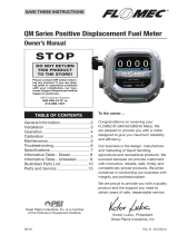
Item No.
No. Part No. Description Req’d.
1 137041-01 Motor, 12 volt ...................................................
1
2
904004-2 Screw, Hex Head Cap ...................................... 4
3 11002502 Motor Shaft Seal .............................................. 1
4 137031-01 Bypass Poppet ................................................ 1
5 137039-06 Spring, Bypass Poppet .................................... 1
6 901003-76 O-Ring .............................................................. 1
7 123038-1 Inlet Strainer ..................................................... 1
8 901003-70 O-Ring .............................................................. 1
9 137014-01 Switch Coverplate ............................................ 1
10 13703004 Bung Adapter ................................................... 1
11 902007-30 Switch .............................................................. 1
12 110360-02 Nozzle Cover .................................................... 1
13 904006-86 Tapping Screw ................................................. 2
14 904002-23 Sems Screw ..................................................... 6
15 904007-65 Washer, Flat ..................................................... 4
16 137007-01 Switch Lever Assembly .................................... 1
17 110017-2 Drive Key .......................................................... 1
18 901003-77 O-Ring .............................................................. 1
19 137012-01 Gear Coverplate ............................................... 1
GPI and the electric gear pump are registered trademarks of Great Plains Industries, Inc.
U.S. Design Patent D543,217
© 2009 GREAT PLAINS INDUSTRIES, INC., Wichita, KS
Printed in U.S.A.
05/09
ILLUSTRATED PARTS LIST
5252 East 36th Street North
W ichita, KS USA 67220-3205
TEL: 316-686-7361
FAX: 316-686-6746
Great Plains Industries, Inc. 5252 E. 36
th
Street North, Wichita, KS USA 67220-3205, hereby provides
a limited warranty against defects in material and workmanship on all products manufactured by
Great Plains Industries, Inc. This product includes a 2 year warranty from date of purchase as
evidenced by the original sales receipt. A 30 month warranty from product date of manufacture
will apply in cases where the original sales receipt is not available. Reference product labeling for
the warranty expiration date based on 30 months from date of manufacture. Manufacturer’s sole
obligation under the foregoing warranties will be limited to either, at Manufacturer’s option, replacing
or repairing defective Goods (subject to limitations hereinafter provided) or refunding the purchase
price for such Goods theretofore paid by the Buyer, and Buyer’s exclusive remedy for breach of
any such warranties will be enforcement of such obligations of Manufacturer. The warranty shall
extend to the purchaser of this product and to any person to whom such product is transferred
during the warranty period.
This warranty shall not apply if:
A.
the product has been altered or modified outside the warrantor’s duly appointed
representative;
B.
the product has been subjected to neglect, misuse, abuse or damage or has been
installed or operated other than in accordance with the manufacturer’s operating
instructions.
To make a claim against this warranty, contact the GPI Customer Service Department at
316-686-7361 or 800-835-0113. Or by mail at:
Great Plains Industries, Inc.
5252 E. 36
th
St. North
Wichita, KS, USA 67220-3205
GPI will step you through a product troubleshooting process to determine appropriate corrective
actions.
GREAT PLAINS INDUSTRIES, INC., EXCLUDES LIABILITY UNDER THIS WARRANTY FOR DIRECT,
INDIRECT, INCIDENTAL AND CONSEQUENTIAL DAMAGES INCURRED IN THE USE OR LOSS OF
USE OF THE PRODUCT WARRANTED HEREUNDER.
The company herewith expressly disclaims any warranty of merchantability or fitness for any
particular purpose other than for which it was designed.
This warranty gives you specific rights and you may also have other rights which vary from U.S.
state to U.S. state.
Note: In compliance with MAGNUSON MOSS CONSUMER WARRANTY ACT – Part 702 (governs
the resale availability of the warranty terms).
Limited Warranty Policy
ELECTRIC MOTOR FOR
HAZARDOUS LOCATIONS
Item No.
No. Part No. Description Req’d.
Items not shown
904002-17 Strain Relief Sealing Grip ................................. 1
110412-15 Power Cord, 14 ga. x 15 ft. (4.6 m) .................. 1
13703002 Suction Pipe ..................................................... 1
136157-01 Hose, (3/4 NPT x 5/8 x 10 ft.)........................... 1
110155-1 Nozzle, Manual 3/4 in., Unleaded .................... 1
906001-4 Pressure Vent Cap (3 psi) ................................. 1
13750003 Gear Kit (includes 2 gears, drive key) .............. 1
13750006 Drive Key Kit (includes drive key) ..................... 1
13750004 Gear Coverplate Kit (includes gear cover-
plate, O-ring #6) .......................................... 1
13750001 Fuse Holder Kit (includes fuse holder,
fuse, wire) .................................................... 1
13750005 Overhaul Kit (includes drive key, motor
shaft seal, 2 gears, O-ring #8, O-ring #6,
O-ring #18) .................................................. 1
13750002 Wet Seal Kit (includes motor shaft seal,
O-ring #6, O-ring #18) ................................. 1
Rev. D 921803-01
/