Page is loading ...

Tyan S1857
Trinity 371
Motherboard Users Manual
Revision 1.20
Copyright © Tyan Computer Corporation, 1999. All rights reserved. No part of this
manual may be reproduced or translated without prior written consent from Tyan
Computer Corp.
All registered and unregistered trademarks and company names contained in this
manual are propery of their respective companies including, but not limited to the
following.
AMIBIOS is a trademark of American Megatrend Incorporated.
Award is a trademark of Phoenix Technologies Ltd.
Windows is a trademark of Microsoft Corporation.
IBM, PC, AT, PS/2 are trademarks of IBM Corporation.
INTEL, Pentium II, Celeron are trademarks of Intel Corporation.
S1857 Trinity 371 are trademarks of TYAN Computer Corporation.
Information contained in this publication has been carefully checked for accuracy and
reliability. In no event will Tyan Computer be held liable for any direct or indirect,
incidental or consequential damage, loss of use, loss of data, or other malady resulting
from errors or inaccuracies of information contained in this manual. The information
contained in this document is subject to change without notice.
PRINTED IN TAIWAN

Table of Contents
1. Introduction.................................................................................................. 4
Overview.............................................................................................4
Icons................................................................................................. 5
BX Chipset Hardware Specifications/Features........................... 6
VIA Chipset Hardware Specifications/Feaures........................... 8
Technical Support............................................................................10
Returning Merchandise for Service...............................................10
2. Board Installation.......................................................................................12
Unpacking....................................................................................... 12
Installation...................................................................................... 12
Quick Reference for Jumpers........................................................ 14
Map of Motherboard Jumpers..................................................... 15
Jumper Settings............................................................................. 17
Clear CMOS & Reset Password .................................................. 18
Soft Power Connector.................................................................... 19
Hardware Reset Switch Connector Installation......................... 20
Creative Labs Audio Connectors ................................................ 20
External SMI.................................................................................... 20
Chassis Intrusion Alarm Connector............................................ 20
CMOS RTC...................................................................................... 20
Flash EEPROM............................................................................... 21
Mounting the Motherboard in the Chassis .............................. 21
Installing Memory.......................................................................... 21
Cache Memory................................................................................ 24
Installing the CPU and Cooling Fan........................................... 25
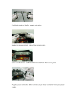
Connecting IDE and Floppy Drives............................................. 29
Connecting the Power Supply...................................................... 32
Installing Add on Cards ............................................................... 33
Connecting PS/2, USB, Serial and Parallel Devices................... 34
3. BIOS Configuration..................................................................................36
Main Setup Menu.......................................................................... 37
Advanced CMOS Setup................................................................ 42
Chipset Setup.................................................................................. 47
Power Management Setup............................................................ 53
Plug and Play Setup....................................................................... 57
Peripherals Setup.............................................................................62

Supervisor and User Security........................................................66
Flash Writer Utility..........................................................................68
4. System Resources......................................................................................70
Beep Codes..................................................................................... 70
Troubleshooting System Problems...............................................71
Displayed Error Messages.............................................................72
Appendix -1 Glossary.....................................................................................74
Appendix -2 Retention module Installaion.................................................81
BIOS -2 Award BIOS Configuration..........................................................86
Main Setup Menu............................................................................89
Standard CMOS Setup....................................................................91
BIOS Features Setup.......................................................................94
Chipset Features Setup...................................................................99
Power Management Setup.............................................................102
PnP/ PCI Configutration.................................................................107
Intergrated Peripherals...................................................................110
Flash Writer Utility..........................................................................113
Compliance Information................................................................................116

http://www.tyan.com
4
Chapter 1
Introduction
Overview
The S1857 Trinity 371 is a quality, high performance motherboard designed for
Socket 370 Intel Celeron and Slot 1 Intel PII/ PIII microprocessors. The Trinity
371 utilizes the Intel 440BX AGPset with AMI BIOS (S1857-B & S1857A-B) or
a VIA VT82C693A with Award BIOS for S1857 & S1857-A models. S1857 can
support Celeron/ PII/ PIII CPU speeds of 300MHz through 600MHz, and host
bus speeds of 66MHz to 133MHz.
( The VIA chipset versions bus speed is Auto-Determined by the CPU. The
BX version can support 133Mhz by overclocking the chipset but it is not
recommended by Intel
TM
and Tyan.)
The S1857 motherboard, with built-in AGP slot, provides high performance
capabilities that are ideal for a wide range of demanding applications such as
CAD, CAM, CAE, desktop publishing, 3D animation, and video production.
This system board in an ATX form factor offers far more features and
expandability than Micro ATX models. Some of the features included are
onboard dual channel PCI PIO, Bus Master IDE and UltraDMA/66, onboard
floppy controller, and onboard high speed I/O.
Flexibility and expandability have been designed into the Trinity 371. With I/O
and drive controller support built onboard, the one AGP slot, six PCI and one
chapter 1
Introduction

S1857 Trinity 371
5
INTRO
ISA slot (one shared, seven usable) are free for numerous add-on expansion
cards.
Remember to take a look at TYAN Computers web site located at
http://www.tyan.com. There you can find information on all of TYANs
products along with FAQs, distributors list, drivers, and BIOS setting explana-
tions.
Icons
In order to help you navigate this manual and set up your system, we have
added several icons to our format.
This icon alerts you to particularly important details regarding the
setup or maintenance of your system. This icon often appears next
to information that may keep you from damaging your board or
system. While we will often point out the most vital paragraphs in a
chapter, you should always read every word in the text. Failing to do so can
lead to exasperation and expense.
Wherever possible, we have included step-by-step instructions for
setting up your system, which are indicated by this icon. However, it
is in your best interest to read an entire section (and perhaps the
entire manual) before you begin to fiddle with your motherboard.
While we have alerted you to potential dangers in several places in
the manual with this icon, these warnings should not be regarded as
the whole of your safety regimen. Never forget that computers are
electrical devices, and are capable of delivering a shock. Prevent damage to
yourself and to your board: always ensure that your system is turned off and
unplugged whenever you are working with it, and that you are equipped with a
static safety device.
!
important!
procedure
1.
2.
3.
warning

http://www.tyan.com
6
Chapter 1
Introduction
S1857-B & S1857A-B
BX Chipset Hardware Specifications/Features
Processor Information One Socket 370 CPU connector
One Slot 1 CPU connector
66/ 100 MHz bus support (BIOS selectable)
Celeron 300 to 533+MHz
Pentium II* and Pentium III up to 600 MHz
*please refer to page 26 for current PII CPU
support
Chipset Information Intel 440BX AGPset with PIIX4e (S1857-B)
Winbond 977 EF Super I/O chipset
Voltage and Power ATX power supply connector
Information +12V power source for DC fan onboard
3.3V DRAM support
Main Memory Up to 768MB onboard
Three 168-pin DIMM sockets
Supports 133MHz SDRAM with SPD
System Management Winbond W83783S
with onboard alarm for monitoring temperature,
supply voltages, and fan speed
Intel LANDesk Client Manager software
option
Expansion Slots One 32-bit AGP slot
Six 32-bit PCI Bus Master slots
One 16-bit ISA slot (shared w/ 1 PCI)
One shared, seven usable slots
Physical Dimensions ATX design
12 inches x 8.35 inches
S1857 requires compatible I/O shield

S1857 Trinity 371
7
BIOS Information AMI Plug and Play flash BIOS (S1857B)
Deep Green, Energy Star, ACPI, Year 2000,
Soft power-down, multiple boot options
Win95/Win98/NT4/Win 2000 ready, DMI 2.0
compliant
PCI 2.2, APM 1.1 compliant (All PCI slots have
a 3.3V standby)
Disk Drive & System I/O Two PCI bus mastering EIDE channels
Supports EIDE CD-ROMs
PIO Mode 3 & 4 (up to 17MB/sec DTR)
UltraDMA/33 bus mastering mode (up to
33MB/sec DTR)
Support for two floppy drives (up to 2.88MB)
Two serial ports (16550 UARTs)
One ECP/EPP parallel port
One IR (InfraRed) I/O interface port header
Two USB rev 1.2 (universal serial bus)
connectors
One PS/2 mouse port
One PS/2 keyboard port
Creative Labs ES 1373 PCI AC97 Codec
Audio (S1857B-A only) Uses a single, shared IRQ
High performance PCI bus master
Spatial enhanced 3D sound (SWS)
Wavetable synthesis built in
Joystick, Audio in, Speaker, Microphone
connectors
Software Specifications
OS Operates with MS-DOS ver 6.22, Windows 98
& Win98 SE, Windows NT 4.0 & SP 4.0,Win
dows 2000 (2072) BETA pending, OS/2 ver 4,
Novell Netware ver 5.0, and SCO Unix ver 5.05
INTRO
Please refer to web for OS updates

http://www.tyan.com
8
S1857 & S1857A
VIA Chipset Hardware Specifications/Features
Processor Information One Socket 370 CPU connector
One Slot 1 CPU connector
66/ 100 / 133MHz bus support (auto-deter
mined by CPU)
Celeron 300 to 533MHz
Pentium II* and Pentium III up to 600MHz
*please refer to page 26 for current PII CPU
support
Chipset Information VIA Apollo Pro 133:VT82C693A+VT82C596B
Winbond 977 EF Super I/O chipset
Voltage and Power ATX power supply connector
Information +12V power source for DC fan onboard
3.3V DRAM support
Main Memory Up to 1.5GB onboard
Three 168-pin DIMM sockets
Supports 133 MHz SDRAM with SPD
System Management Winbond W83783S
with onboard alarm for monitoring temperature,
supply voltages, and fan speed
Intel LANDesk Client Manager software
option
Expansion Slots One 32-bit AGP slot
Six 32-bit PCI Bus Master slots
One 16-bit ISA slots (shared w/ 1 PCI)
One shared, seven usable slots
Physical Dimensions ATX design
12 inches x 8.35 inches
S1857 requires compatible I/O shield
Chapter 1
Introduction

S1857 Trinity 371
9
BIOS Information Award Plug and Play flash BIOS
Deep Green, Energy Star, ACPI, Year 2000,
Soft power-down, multiple boot options
Win95/Win98/NT4/Win2000 ready, DMI 2.0
compliant
PCI 2.2, APM 1.1 compliant (All PCI slots have
a 3.3V standby)
Disk Drive & System I/O Two PCI bus mastering EIDE channels
Supports EIDE CD-ROMs
PIO Mode 3 & 4 (up to 17MB/sec DTR)
UltraDMA/66 bus mastering mode (up to
66MB/sec DTR)
Support for two floppy drives (up to 2.88MB)
Two serial ports (16550 UARTs)
One ECP/EPP parallel port
One IR (InfraRed) I/O interface port header
Two USB rev 1.2 (universal serial bus)
connectors
One PS/2 mouse port
One PS/2 keyboard port
Creative Labs ES 1373 PCI AC97 Codec
Audio (S1857A only) Uses a single, shared IRQ
High performance PCI bus master
Spatial enhanced 3D sound (SWS)
Wavetable synthesis built in
Joystick, Audio in, Speaker, Microphone
connectors
Software Specifications
OS Operates with MS-DOS ver 6.22, Windows 98
& Win98 SE, Windows NT 4.0 & SP 4.0,
Windows 2000(2072) BETA pending, OS/2 ver
4, Novell Netware ver 5.0, and SCO Unix ver
5.05
INTRO
Please refer to web for OS updates

http://www.tyan.com
10
Chapter 1
Introduction
Technical Support
If a problem arises with your system, you should turn to your dealer for help
first. Your system has most likely been configured by them, and they should
have the best idea of what hardware and software your system contains.
Hence, they should be of the most assistance. Further, if you purchased your
system from a dealer near you, you can actually bring your system in to them
to have it serviced, instead of attempting to do so yourself (which can have
expensive consequences).
Help resources:
1. See FAQ and beep codes sections of this manual.
2. See Tyan web site for FAQ, bulletins, driver updates, etc.
http://www.tyan.com
3. Contact your dealer or distributor for help BEFORE calling Tyan.
4. Check the Tyan user group: alt.comp.periphs.mainboard.tyan
Returning Merchandise for Service
During the warranty period, contact your distributor or system vendor FIRST
for any product problems. This warranty only covers normal customer use and
does not cover damages incurred during shipping or failure due to the
alteration, misuse, abuse, or improper maintenance of products.
For Resellers Only:
A receipt or copy of your invoice marked with the date of purchase is required
before any warranty service can be rendered. You can obtain service by calling
the manufacturer for a Return Merchandise Authorization (RMA) number. The
RMA number should be prominently displayed on the outside of the shipping
carton and the package should be mailed prepaid, or hand-carried to the
manufacturer. TYAN will pay to have the board shipped back to you.

S1857 Trinity 371
11
This page left blank intentionally.

http://www.tyan.com
12
Chapter 2
Board Installation
chapter 2
Board Installation
Unpacking
The motherboard package should contain the following:
(1) S1857 mainboard
(1) 40-pin IDE and 34-pin floppy cable pack
(1) 80-pin ATA-66 IDE cable (S1857 & S1857A only)
(1) S1857 Users Manual
(1) Driver CD
(1) URM Retention Module
Installation
You are now ready to install your motherboard. The mounting hole pattern of
the S1857 matches the ATX system board specifications. Your chassis should
support a standard ATX mainboard form factor.
How to install our products right...the first time.
Whats the first thing I should do?
The first thing you should do is read this users manual. It contains important
information which will make configuration and setup much easier.

S1857 Trinity 371
13
procedure
1.
2.
3.
INSTALL
Here are some precautions you should follow when installing your mother-
board:
(1) Ground yourself properly before removing your motherboard
from the antistatic bag. Unplug the power from your computer
and then touch any metal part on the computer case. (Or wear a
grounded wrist strap.)
(2) Hold the motherboard by its edges and do not touch the bottom of
the board.
(3) Avoid touching motherboard components, IC chips, connectors,
and leads.
(4) Avoid touching pins of memory modules and chips.
(5) Place motherboard on a grounded antistatic surface or on the
antistatic bag.
Having reviewed the precautions above, the next step is to take the mother-
board out of the cardboard box and static bag, hold it by its edges, and place it
on a grounded antistatic surface, component side up. Inspect the board for
damage.
DO NOT APPLY POWER TO THE BOARD IF IT HAS BEEN DAMAGED!
Press down on any of the socket ICs if it appears that they are not properly
seated (the board should still be on an antistatic mat). Do not touch the bottom
of the board. Remember, dont take any electronic device out of its protective
bag until you are ready to actually install it into the computer case. If you do
not ground yourself, you risk zapping the motherboard or adapter card.
Subsequent problems may not arise immediately because electrostatic dis-
charge damage, unlike physical damage, causes the device to fail over time.
Installation Steps
1. Set Jumpers
2. Mount Motherboard in Chassis
3. Install Memory
4. Install CPU & Cooling Fan
5. Connect IDE and Floppy Drives
6. Connect Power Supply
7. Install Add-on Cards
8. Connect PS/2, USB, Serial and Parallel Devices
!
important!

http://www.tyan.com
14
Chapter 2
Board Installation
Quick References for Jumpers
In this manual, the terms closed and on are used when referring to jumpers
(or jumper pins) that are active; open and off are used when referring to
jumpers (or jumper pins) that are inactive. See the Figure 2-1 for examples of
on and off pins and jumpers. The square pin in the diagram is Pin 1.
Jumpers and pins are connected by slipping the blue plastic jumper connector
overtop of two adjacent jumper pins (indicated by 1-2 or 2-3). The metal rod
inside the plastic shell bridges the gap between the two pins, completing the
circuit. See Figure 2-2 for more example of pin connections.
Figure 2-1 Figure 2-2
The tables and maps on the following pages will help you set the jumpers for
CPU speed, Infrared, and external connector pin assignments, among others.
The miniature motherboard maps will help you locate the jumpers on your board.
A full-page map of the motherboard can be found on the next two pages.
2 pin jumpers
off on
3 (or more) pin jumpers
1-2 2-3 open
1
2
3
1
2
3
1
2
3

S1857 Trinity 371
15
The tiny 1s next to jumpers of 3 pins or more indicate the position of pin 1
for that jumper.
Figure 2-3 : Map of Motherboard Jumpers
JP10
JP11
JP12
JP13
USB1
Keyboard
USB0
Mouse
Primary IDE connector
COM2 COM1
Printer Port
PCI slot 2
PCI slot 3
AGP port
PCI slot 4
PCI slot 5
PCI slot 6
ISA slot 1
Flash BIOS
J7
PCI slot 1
Secondary IDE connector
Floppy drive connector
1
J23
(VIDEO)
1
J22
(CD)
J21
1
1
1
CON3 (WOL)
CON2 (WOR)
Joystick
Line inMicrophone in
Line out
J12
SPKR
1
3 volt
lithium
battery
ATX power connector
1
1
Intel 440BX
Intel 440BX
Creative
ES1373
FAN4
1
JP17
J20
(MPEG)
1
Winbond
1
1
JP2
DIMM bank 2
DIMM bank 3
DIMM bank 1
J16
1
FAN3
1
EXTSMI
JP16
D31
1
Slot 1 Type CPU
FAN1
1
W83783S
Socket 370
CPU
PGA370
(On S1857A & S1857A-B only)
J18
(Reserved)
INSTALL
FS1
FS0

http://www.tyan.com
16
Chapter 2
Board Installation
Winbond Super I/O
3 DIMM slots
Socket 370 for
Celeron CPU
PS/2 Mouse &
Keyboard
ports
Floppy port
ATX power
supply header
6 PCI slots
1 ISA slot
2x AGP port
2 USB ports
1 Parallel, 2 Com
ports
2-ch EIDE
Intel 440BX or Via Apollo
Pro Plus AGPset
BIOS
Audio ports(On S1857-
A &S1857A-B Only)
Joystick,
Figure 2-4 : Map of S1857 Features
Slot 1 Type for
Celeron CPU
Battery

S1857 Trinity 371
17
1. Setting Jumpers
1-A. CPU Speed Settings (Jumpers JP10, JP11, JP12, JP13)
There are two steps to set the CPU speed. First, set the clock multiplier with
jumpers JP10 -13 according to the specification of your CPU using the chart
below. After the system is ready to boot up you will need to set the bus speed
in the BIOS setup. This is covered in detail in Chapter 3 of this manual.
Presently all Celeron CPUs use a 66MHz bus speed. (Tyan does not recom-
mend operating CPUs, memory, or PCI Bus at higher than rated speed. Tyan
takes no responsibility for any problems related to overclocking any bus or
component on the system board.)
!
important!
Multiplier Bus Speed
(set Jmprs
on board)
(set in
BIOS)
100 350
133* 466
100 400
133* 533
66 300
100 450
133* 600
66 333
100 500
133* 667
66 366
100 550
133* 733
66 400
100 600
133* 800
66 433
100 650
133* 800
66 466
100 700
133* 933
ON OFF ON OFF
ON ON OFF OFF
ON ON ON OFF
OFF OFF OFF ON
OFF OFF ON ON
OFF ON OFF ON
JP13
OFF ON ON ON
ON OFF OFF ON
CPU speed JP10 JP11 JP12
3.5
4
4.5
5
5.5
6
6.5
7
* The VIA chipset versions bus speed is Auto-Determined by the CPU. The BX
version can support 133Mhz by overclocking
the chipset but it is not recommended by
Intel
TM
and Tyan.
Currently S1857 does not support some
older Slot 1, 66Mhz bus Pentium IIs
that use a 2.8 core voltage. Please refer
to the link on page 26 for the most
updated information on CPU support
for the Trinity 371.
JP10, JP11,
JP12, JP13
INSTALL

http://www.tyan.com
18
Chapter 2
Board Installation
1-B. Panel Connector Settings (Jumper J16)
Power LED:
For 2-pin: bicolor/single
color - Use pins 2-4
1-C. BUS Speed Settings (FS0, FS1)
1-D. Speaker Connector (Jumper J12)
The speaker should be connected to pins 1-4 of jumper J12. As default,
pins 3-4 of jumper J12 are connected to the internal buzzer.
1-E. Wake-On LAN (CON3)
1-F. Wake-On Ring (CON2)
1-G. Clear CMOS and Reset Password (Jumper JP2)
tluafeDteseR
2PJ
2-13-2
HDD LED+ 12 Power LED
HDD LED- 34 Sleep LED
Ground 56Power On/Off
Reset 78 Ground
IR +5V 910 No Connect
IR Receive 11 12 Power +5V
Ground 13 14 No Connect
IR Transmit 15 16 No connect
No Connect 17 18 No Connect
Top
Bottom
J16
1 3 5 7 9 11131517
2 4 6 8 10 12 14 16 18
0SF1SF
ffOffO
zhM331tceteD-otuA/otuA
UPCaiv
ffOnO zhM001
nOnO zhM66
133Mhz BUS Speed can only
be set if the CPU supports a
133 Mhz Front Side BUS.

S1857 Trinity 371
19
!
important!
If you have been locked out of your system because you forgot your pass-
word or set the CMOS incorrectly, follow the instructions below.
1. Power off the system
2. Set jumper JP2 to pins 2 and 3
3. Wait for 2 seconds, then return jumper JP2 to pins 1 and 2.
4. Power on the system again.
By following this procedure, you will erase your password and reset the
CMOS to the BIOS defaults.
1-H Fan Speed Detect
When using Intels LANDesk system management software, you may monitor
the status of the CPU Fans by connecting them to the Fan1 connector. You
will NOT be able to monitor your CPU fan with the other Fan connectors.
1-I Soft Power Connector
The Soft Power Connector is part of
jumper block J16. The Trinity 371 uses
the chipset for power management,
including turning on and off the
system. If the Power Button Function
option in the BIOS Power Manage-
ment Menu is set to On/Off (which is
the default), pressing the power
button once after the BIOS has booted
up will turn the system on and off. If
the Power Button Function option is
set to Suspend, pressing the power
button once will wake the system or
send it to Suspend mode. In this case,
you cannot turn the system off unless
you shut down through the Windows
operating system or you hold the
power button down for four seconds.
1-J Sound disable (JP17)
By closing this jumper you will disable the on-board sound support which is
routed through the Creative Labs ES 1373 PCI sound chip.
The settings are closed (No onboard sound) or Open (Default).
1-K. Reserved Factory Header (J18)
This five pin header is reserved for factory settings in which future upgrades
INSTALL
FS0,FS1
(BUS
Speed)
CON3
(WOL)
J16
J12 (Speaker)
CON2
(WOR)
JP2 (Clr
CMOS)
JP17
(Sound
Enable)

http://www.tyan.com
20
Chapter 2
Board Installation
to the boards functionalitiy may be increased. This header should be left
untouched.
1-L Hardware Reset Switch Connector Installation
The Reset switch on your cases display panel provides you with the Hard-
ware Reset function, which is the same as power on/off. The system will do a
cold start after the Reset button is pushed. (J16 pin 7 & 8)
1-M Creative Labs Audio Connectors
There are four black 4-pin connectors onboard which are used for various
peripherals audio signals. The digital signal that comes in through these
connectors is directed through the Creative Labs ES1373 PCI sound chip, and
the digital signal is turned into an audio signal which goes out through the
speaker. The TDA connector (J21) is for modem audio; the MPEG connector
(J20) is for DVD and TV cards; the VIDEO connector is (J22); the CD connector
(J23) is for CD-ROMs.
1-N External SMI
The EXTSMI (External System Management Interface) connector, jumper JP16,
is used by some plug-in cards. Certain applications associated with these plug-
in cards use the interface for hardware control and queries.
1-O Intrusion Alarm Connector
The J7 connector is an intrusion alarm, that can be connected to the system
chassis. When active (J7 is connected to the chassis), this alarm will alert the
system administrator anytime someone opens the systems case.
1-P Power LED Connector
Jumper D31 is a three pin power LED header that can be used if you have a 3
pin Power LED. Otherwise refer to panel connector J16 for 2 pin LEDs. 3 pin
LEDs can still be used on J16 where pin 13 would be for the Ground pin.
CMOS RTC
The Real Time Clock (RTC) circuit, which provides the date and time for the
system is integrated into the 440BX or Via Apollo Pro Plus AGPset. If the
external battery for the RTC is low, it will prevent your system from POSTing,
and you will not get a display. Normally the life span of an external battery is 2
years. If yours is running low, you will need to replace it with a new 3V lithium
battery (Sony CR2032).
/