
Trinity KT400 S2495 User’
s Manual
i
http://www.tyan.com
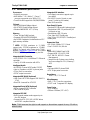
Trinity KT400
///
S2495
Revision 1.02
Copyright © TYAN Computer Corporation, 2003. All rights reserved. No part of this manual
may be reproduced or translated without prior written consent from TYAN Computer Corp.
All registered and unregistered trademarks and company names contained in this manual are
property of their respective owners including, but not limited to the following.
TYAN, Trinity, KT400 and S2495 are trademarks of TYAN Computer Corporation.
AMD, Athlon and Duron are trademarks of Advanced Micro Devices, Inc.
VIA, KT400, are trademarks of VIA Technologies, Inc.
Silicon Image is a trademark of Silicon Image, Inc.
High Point is a trademark of HighPoint Technologies, Inc.
Award, AwardBIOS are trademarks of Award Software Incorporated.
Microsoft and Windows are trademarks of Microsoft Corporation.
IBM, PC, AT and PS/2 are trademarks of IBM Corporation.
Winbond is a trademark of Winbond Electronics Corporation.
Sony/Philips Digital Interface (SPDIF) is a trademark of Sony Corporation and Philips
Electronics.
Portable Document Format (PDF) is a trademark of Adobe Corporation.
Information contained in this document is furnished by TYAN Computer Corporation and has
been reviewed for accuracy and reliability prior to printing. TYAN assumes no liability
whatsoever, and disclaims any express or implied warranty, relating to sale and/or use of
TYAN products including liability or warranties relating to fitness for a particular purpose or
merchantability. TYAN retains the right to make changes to product descriptions and/or
specifications at any time, without notice. In no event will TYAN be held liable for any direct or
indirect, incidental or consequential damage, loss of use, loss of data or other malady resulting
from errors or inaccuracies of information contained in this document.

Trinity KT400 S2495
Table of Contents
ii
http://www.tyan.com
Table of Contents
Before you begin… ................................................................................................................iii
Chapter 1: Introduction.......................................................................................................1-1
1.1 – Congratulations!.....................................................................................................1-1
1.2 – Hardware Specifications........................................................................................1-2
Chapter 2: Board Installation..............................................................................................2-1
2.1 – Board Image ..........................................................................................................2-2
2.2 – Board Parts............................................................................................................2-3
2.3 – Jumper Settings & Definitions................................................................................2-4
2.4 – Connector Description............................................................................................2-5
2.5 – Mounting the Motherboard...................................................................................2-13
2.6 – Installing the Memory...........................................................................................2-14
2.7 – Memory Installation Procedure.............................................................................2-15
2.8 – Installing the Processor and Heatsink..................................................................2-16
2.9 – Attaching Drive Cables.........................................................................................2-18
2.10 – Installing Add-In Cards.......................................................................................2-20
2.11 – Connecting External Devices.............................................................................2-21
2.12 – Installing the Power Supply................................................................................2-21
2.13 – Finishing Up .......................................................................................................2-22
Chapter 3: BIOS Setup.........................................................................................................3-1
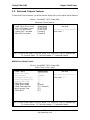
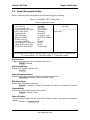
3.1 – Main BIOS Setup ...................................................................................................3-3
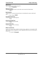
3.2 – Standard CMOS Features......................................................................................3-5
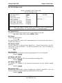
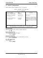
3.3 – Advanced BIOS Features......................................................................................3-7
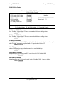
3.4 – Advanced Chipsets Features...............................................................................3-10
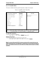
3.5 – Integrated Peripherals..........................................................................................3-14
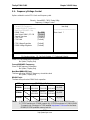
3.6 – Power Management Setup...................................................................................3-19
3.7 – PnP/PCI Configurations.......................................................................................3-23
3.8 – PC Health Status .................................................................................................3-24
3.9 – Frequency/Voltage Control..................................................................................3-25
3.10 – Load Fail-Safe Defaults......................................................................................3-26
3.11 – Load Optimized Defaults....................................................................................3-26
3.12 – Supervisor/User Password Setting.....................................................................3-27
3.13 – Exit Selecting.....................................................................................................3-28
Chapter 4: Diagnostics........................................................................................................4-1
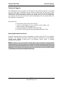
4.1 Beep Codes..............................................................................................................4-1
4.2 Flash Utility ...............................................................................................................4-1
Appendix I: Glossary...........................................................................................................5-1
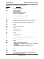
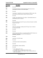
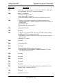
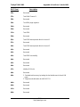
Appendix II: Post Error Code for BIOS...............................................................................5-7
Technical Support.........................................................................................................5-15

Trinity KT400 S2495 Before you begin…
iii
http://www.tyan.com
Before you begin…
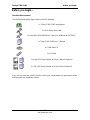
Check the box contents!
The retail motherboard package should contain the following:
1x Trinity KT400 S2495 motherboard
1x 34-Pin floppy drive cable
1x Ultra-DMA -133/100/66/33 IDE cable (One additional for IDE RAID)
1x Trinity KT400 S2495 User’s Manual
1x TYAN driver CD
1x I/O shield
1 x Serial ATA Driver Diskette and User’s Manual (Optional)
1 x IDE RAID Driver Diskette and User’s Manual (Optional)
If any of these items are missing, please contact your vendor/dealer for replacement before
continuing with the installation process.

Trinity KT400 S2495
Chapter 1: Introduction
1-1
http://www.tyan.com
Chapter 1: Introduction
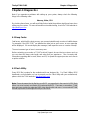
1.1 – Congratulations!
You have purchased one of the most powerful solutions for the AMD Athlon XP processor, the
Trinity KT400 S2495. Based on VIA’s KT400 chipsets, the main features of the Trinity KT400
S2495 are: ATX form factor, onboard 10/100 Fast Ethernet port, and 6-channel audio. It also
offers optional features such as Serial ATA and IDE RAID for desktop demands.
Remember to visit TYAN’s Website at http://www.tyan.com. There you can find information on
all of TYAN’s products with FAQs, distributors list, and BIOS setting explanations.

Trinity KT400 S2495
Chapter 1: Introduction
1-2
http://www.tyan.com
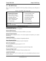
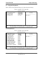
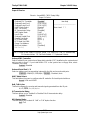
1.2 – Hardware Specifications
Processors
• Socket A processor
• AMD Athlon™ XP / Athlon™ / Duron™
processor supports up to 3000+ CPU
• Front-Side Bus support for 200/266/333MHz
Chipset
• VIA KT400 North Bridge chipset
• VIA VT8235 South Bridge chipset
• Winbond W83697HF LPC I/O chip
Memory
• Three 184-pin DIMM sockets
• Supports DDR 400*/333/266/200
• Up to 3GB Registered, unbuffered non-ECC
type memory modules
* NOTE: PC2700 maximum to 2 DIMM
support only. PC3200 maximum to 1 DIMM
(DIMM 3) support only. Please go to TYAN
website http://www.TYAN.com for the latest
DDR400/PC3200 qualified memory test list.
Integrated LAN Controller
• VIA VT6103 PHY 10/100Base-TX Ethernet
controller
• One RJ-45 LAN connector with LEDs
Intelligent Audio
• ALC650 6-Channel AC97 audio CODEC
• Line-in / Speaker-out / MIC-in phone jacks
• CD-in / Aux-in connectors
• SPDIF output connector
Integrated IDE RAID (Optional)
• High Point HPT372N supports IDE RAID 0,
1, 0+1
• Dual IDE channels for ATA 133
Integrated Serial ATA (Optional)
• Silicon Image SiI3112 controller
• Two Serial ATA ports
Integrated PCI IDE
• Dual channel master mode support up to
four IDE devices
• Support for ATA-133 / 100 / 66 IDE drives
and ATAPI compliant devices
Integrated I/O Interface
• One floppy connector supports up to
two drives
• Six USB 2.0 ports (4 ports on rear
panel, 2 ports by pin-header)
• One IrDA connector
Rear Panel I/O ports
• Stacked PS/2 Mouse & Keyboard ports
• Stacked two USB 2.0 ports and RJ45
LAN port on top
• Stacked two USB 2.0 ports
• Two 9-pin UART Serial ports
• One 25-pin SPP/ECP/EPP Parallel port
• Audio jacks
Expansion Slots
• Six 32-bit / 33MHz PCI 2.2 slots
• One 1.5V AGP 4X / 8X slot
BIOS
• Award BIOS 4Mbit Flash ROM
• Support APM 1.2 & ACPI 1.0B
• PnP, DNI 2.0, WFM 2.0 Power
Management
• Jumper free for System over clocking
and over voltage for CPU / Memory /
AGP
Power
• On board VRM, 2-phase PWM
• ATX 20-pin power connector
Regulatory
• EMI - CE, FCC Class B
Miscellaneous
• WOL, STR, Three fan connectors
• POST code 7-segment LED display
Form Factor
• ATX footprint
• 305mm x 245mm (12” x 9.6”)
Note: TYAN reserves the right to add support or discontinue support for any OS with or
without notice.

Trinity KT400 S2495 Chapter 2: Board Installation
2-1
http://www.tyan.com
Chapter 2: Board Installation
Installation
You are now ready to install your motherboard. The mounting holes pattern of the Trinity
KT400 S2495 matches the ATX specification. Before continuing with installation, confirm that
your chassis supports a standard ATX motherboard.
How to install our products right…. the first time!
The first thing you should do read this user’s manual. It contains important information that
will make configuration and setup much easier. Here are some precautions you should take
when installing your motherboard:
(1) Ground yourself properly before removing your motherboard from the antistatic bag.
Unplug the power from your computer power supply and then touch a safely
grounded object to release static charge (i.e. power supply case). For the safest
conditions, TYAN recommends wearing a static safety wrist strap.
(2) Hold the motherboard by its edges and do not touch the bottom of the board, or flex
the board in any way.
(3) Avoid touching the motherboard components, IC chips, connectors, memory
modules and leads.
(4) Place the motherboard on a grounded antistatic surface or on the antistatic bag that
the board was shipped in.
(5) Inspect the board for damage.
The following pages include details on how to install your motherboard into your chassis, as
well as installing the processor, memory, disk drives and cables.
Note: DO NOT APPLY POWER TO THE BOARD IF IT HAS BEEN DAMAGED

Trinity KT400 S2495 Chapter 2: Board Installation
2-2
http://www.tyan.com
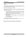
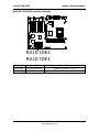
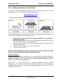
2.1 – Board Image
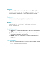
The following is an image of the Trinity KT400 S2495.
The above photograph is purely representative. Due to engineering updates and new
board revisions, certain components may change and or be repositioned. The picture
above may or may not look exactly like the board you received.
The following page includes details on the vital components of this motherboard.

Trinity KT400 S2495 Chapter 2: Board Installation
2-3
http://www.tyan.com
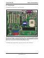
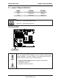
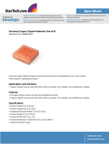
2.2 – Board Parts
Ÿ
S2495
CPU
USB3
1
1
1
1
1
1
1
1
1
1
1
KB1
USB1
COM1
COM2
LPT1
FAN1
ATX1
USB2
AUD2
CD1
AUX1
AUD1
ALC650
SPDIF1
FAN3
JCK1
JCK2
VT6103
AGP1
W83697HF
GAME1
BIOS
WOL
FAN2
VIA KT400
VT8377
VIA
VT8235
PCI1PCI2PCI3PCI4PCI5PCI6
SATA2
SATA1
FDD
LED2
CMOS
BAT1
(Optional)
(Optional)
HPT372N
(Optional)
SII3112
(Optional)
(Optional)
(Optional)
PRI-IDE
SEC-IDE
RAID IDE2
RAID IDE1
J1
LED1
DIMM1
DIMM2
DIMM3
1
2
17
18
This jumper diagram is representative of the latest board revision available at the time
of publishing. The board you receive may or may not look exactly like the above
diagram. The board parts are not to scale.

Trinity KT400 S2495 Chapter 2: Board Installation
2-4
http://www.tyan.com
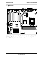
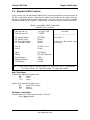
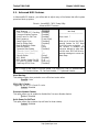
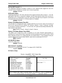
2.3 – Jumper Settings & Definitions
Jumper Function Ref. Page
CMOS Clear CMOS Page 2-4
JCK1 FSB Select Page 2-5
JCK2 FSB Select Page 2-5
Jumper Example
Jumper OFF – open (without jumper cap)
Jumper ON – closed (with jumper cap)
CMOS Reset (CMOS)
S2495
CPU
USB3
1
1
1
1
1
1
1
1
1
1
1
KB1
USB1
COM1
COM2
LPT1
FAN1
ATX1
USB2
AUD2
CD1
AUX1
AUD1
ALC650
SPDIF1
FAN3
JCK1
JCK2
VT6103
AGP1
W83697HF
GAME1
BIOSWOL
FAN2
VIA KT400
VT8377
VIA
VT8235
PCI1PCI2PCI3PCI4PCI5PCI6
SATA2
SATA1
FDD
LED2
CMOS
BAT1
(Optional)
(Optional)
HPT372N
(Optional)
SII3112
(Optional)
(Optional)
(Optional)
PRI-IDE
SEC-IDE
RAID IDE2
RAID IDE1
J1
LED1
DIMM1
DIMM2
DIMM3
CMOS
1
Normal
1
Clear CMOS
You can reset the CMOS settings in case an incorrect setting causes
system instability or you have forgotten your system/setup password or
have just flashed your BIOS by using these jumpers.
- Power off system, disconnect power supply from motherboard
- Set jumper to Clear CMOS
- Wait about 5 seconds
- Set jumper to Normal (Default)

Trinity KT400 S2495 Chapter 2: Board Installation
2-5
http://www.tyan.com
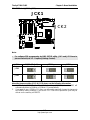
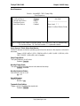
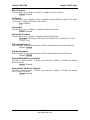
CPU FSB Select (JCK1 & JCK2)
S2495
CPU
USB3
1
1
1
1
1
1
1
1
1
1
1
KB1
USB1
COM1
COM2
LPT1
FAN1
ATX1
USB2AUD2
CD1
AUX1
AUD1
ALC650
SPDIF1
FAN3
JCK1
JCK2
VT6103
AGP1
W83697HF
GAME1
BIOSWOL
FAN2
VIA KT400
VT8377
VIA
VT8235
PCI1PCI2PCI3PCI4PCI5PCI6
SATA2
SATA1
FDD
LED2
CMOS
BAT1
(Optional)
(Optional)
HPT372N
(Optional)
SII3112
(Optional)
(Optional)
(Optional)
PRI-IDE
SEC-IDE
RAID IDE2
RAID IDE1
J1
LED1
DIMM1
DIMM2
DIMM3
JCK1
JCK1
JCK2
Note:
Ÿ For software FSB programming by BIOS SETUP utility, JCK1 and JCK2 have to
place at Default (see 3.9 – Frequency/Voltage Control).
JCK# 100MHz*(Default) 133MHz 166MHz
JCK1
1 3
1 3
. 1 3
JCK2
1 3
1 3
1 3
About the jumpers setting (JCK1 & JCK2) please see the following information:
1. If JCK1 and JCK2 are left in their default settings (100MHz) then the BIOS will
automatically detect a 100MHz or 133MHz CPU automatically.
2. If you want to use a 333MHz CPU then you will need to manually change the jumpers to
the 166MHz setting, however if you set the CPU FSB to this speed then you'll only be
able to run the memory at DDR333.

Trinity KT400 S2495 Chapter 2: Board Installation
2-6
http://www.tyan.com
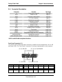
2.4 – Connector Description
Connector Function Ref. Page
J1 Front panel connector Page 2-6
LED1 Power On LED Page 2-7
LED2 Post error code for BIOS Page 5-7
FAN1 CPU fan connector Page 2-7
FAN2 Chassis fan connector Page 2-7
FAN3 Power fan connector Page 2-7
USB3 USB header #3 Page 2-8
WOL Wake On LAN Page 2-8
CD1 CD Audio-in connector Page 2-9
AUX1 Auxiliary Line-In connector Page 2-9
AUD1 Front Audio Page 2-10
GAME1 Game port connector Page 2-10
SPDIF1 Sony/Philips Digital InterFace connector Page 2-11
SATA1/SATA2* Serial ATA connector Page 2-11
RAID IDE1/RAID IDE2*
IDE RAID connector Page 2-12
* SATA and IDE RAID are optional functions.
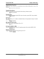
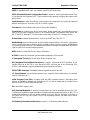
Front Panel Connector (J1)
Your chassis will usually come with connectors to install onto the motherboard, such as HD
and Power LEDs. The Front Panel Connector (J1) has been implemented for such purposes.
2
1
18
17
(1, 3) HD-LED
(5, 7) RESET
(9, 11, 13, 15, 17) IR
(2, 4, 6) PW-LED
(8, 10) PW-ON
(12, 14, 16, 18) SPEAKER
Pin 2
Pin 4 Pin 6
Pin 8
Pin 10
Pin 12
Pin 14
Pin 16
Pin 18
POWER
_ LED
GND GND
POWER
BUTTON
GND
VCC
GND NC SPEAKER
Pin 1
Pin 3 Pin 5
Pin 7
Pin 9
Pin 11
Pin 13
Pin 15
Pin 17
VCC HDD_LED
GND
REST
BUTTON
VCC CIRRX
IRRX
GND IRTX

Trinity KT400 S2495 Chapter 2: Board Installation
2-7
http://www.tyan.com
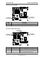
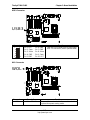
LED Information (LED1 & LED2)
S2495
CPU
USB3
1
1
1
1
1
1
1
1
1
1
1
KB1
USB1
COM1COM2
LPT1
FAN1
ATX1
USB2AUD2
CD1
AUX1
AUD1
ALC650
SPDIF1
FAN3
JCK1
JCK2
VT6103
AGP1
W83697HF
GAME1
BIOS
WOL
FAN2
VIA KT400
VT8377
VIA
VT8235
PCI1PCI2
PCI3
PCI4
PCI5PCI6
SATA2
SATA1
FDD
LED2
CMOS
BAT1
(Optional)
(Optional)
HPT372N
(Optional)
SII3112
(Optional)
(Optional)
(Optional)
PRI-IDE
SEC-IDE
RAID IDE2
RAID IDE1
J1
LED1
DIMM1
DIMM2
DIMM3
LED1
LED2
LEDs Description
LED1 Power on LED
LED2 Post error code for BIOS (Ref. Appendix II)
Fan Connector (FAN1 & FAN2 & FAN3)
S2495
CPU
USB3
1
1
1
1
1
1
1
1
1
1
1
KB1
USB1
COM1
COM2
LPT1
FAN1
ATX1
USB2AUD2
CD1
AUX1
AUD1
ALC650
SPDIF1
FAN3
JCK1
JCK2
VT6103
AGP1
W83697HF
GAME1
BIOS
WOL
FAN2
VIA KT400
VT8377
VIA
VT8235
PCI1PCI2PCI3PCI4PCI5PCI6
SATA2
SATA1
FDD
LED2
CMOS
BAT1
(Optional)
(Optional)
HPT372N
(Optional)
SII3112
(Optional)
(Optional)
(Optional)
PRI-IDE
SEC-IDE
RAID IDE2
RAID IDE1
J1
LED1
DIMM1
DIMM2
DIMM3
FAN1
FAN2
FAN3
Fan # Description Functions
1 CPU fan RPM Read and controlled
2 Chassis fan RPM Read and controlled
3 Power fan The fan connector does not support RPM function
which can not detect speed of the fan.

Trinity KT400 S2495 Chapter 2: Board Installation
2-8
http://www.tyan.com
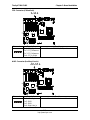
USB3 Connector
S2495
CPU
USB3
1
1
1
1
1
1
1
1
1
1
1
KB1
USB1
COM1
COM2
LPT1
FAN1
ATX1
USB2
AUD2
CD1
AUX1
AUD1
ALC650
SPDIF1
FAN3
JCK1
JCK2
VT6103
AGP1
W83697HF
GAME1
BIOSWOL
FAN2
VIA KT400
VT8377
VIA
VT8235
PCI1PCI2PCI3PCI4PCI5PCI6
SATA2
SATA1
FDD
LED2
CMOS
BAT1
(Optional)
(Optional)
HPT372N
(Optional)
SII3112
(Optional)
(Optional)
(Optional)
PRI-IDE
SEC-IDE
RAID IDE2
RAID IDE1
J1
LED1
DIMM1
DIMM2
DIMM3
USB3
Connector Description Functions
1
5
6
10
Pin 1: VCC
Pin 2: -Data
Pin 3: +Data
Pin 4: GND
Pin 5: GND
Pin 6: GND
Pin 7: GND
Pin 8: +Data
Pin 9: -Data
Pin 10: VCC
Use the USB3 header here for front panel
USB 2.0 connectors (via an optional cable)
WOL Connector
S2495
CPU
USB3
1
1
1
1
1
1
1
1
1
1
1
KB1
USB1
COM1
COM2
LPT1
FAN1
ATX1
USB2
AUD2
CD1
AUX1
AUD1
ALC650
SPDIF1
FAN3
JCK1
JCK2
VT6103
AGP1
W83697HF
GAME1
BIOS
WOL
FAN2
VIA KT400
VT8377
VIA
VT8235
PCI1PCI2PCI3PCI4PCI5PCI6
SATA2
SATA1
FDD
LED2
CMOS
BAT1
(Optional)
(Optional)
HPT372N
(Optional)
SII3112
(Optional)
(Optional)
(Optional)
PRI-IDE
SEC-IDE
RAID IDE2
RAID IDE1
J1
LED1
DIMM1
DIMM2
DIMM3
WOL
Connector
Description Functions
WOL Wake On LAN Reserved for a network interface card to wake the
system from power saving mode.

Trinity KT400 S2495 Chapter 2: Board Installation
2-9
http://www.tyan.com
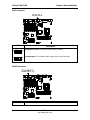
CD1 Connector (CD Audio-In)
S2495
CPU
USB3
1
1
1
1
1
1
1
1
1
1
1
KB1
USB1
COM1
COM2
LPT1
FAN1
ATX1
USB2
AUD2
CD1
AUX1
AUD1
ALC650
SPDIF1
FAN3
JCK1
JCK2
VT6103
AGP1
W83697HF
GAME1
BIOS
WOL
FAN2
VIA KT400
VT8377
VIA
VT8235
PCI1PCI2PCI3PCI4PCI5PCI6
SATA2
SATA1
FDD
LED2
CMOS
BAT1
(Optional)
(Optional)
HPT372N
(Optional)
SII3112
(Optional)
(Optional)
(Optional)
PRI-IDE
SEC-IDE
RAID IDE2
RAID IDE1
J1
LED1
DIMM1
DIMM2
DIMM3
CD1
Connector
Description Functions
1 4
Pin 1: CD_In_Left
Pin 2: CD_Reference
Pin 3: CD_Reference
Pin 4: CD_In_Right
Connect CD-ROM (DVD) audio out
AUX1 Connector (Auxiliary Line-In)
S2495
CPU
USB3
1
1
1
1
1
1
1
1
1
1
1
KB1
USB1
COM1
COM2
LPT1
FAN1
ATX1
USB2
AUD2
CD1
AUX1
AUD1
ALC650
SPDIF1
FAN3
JCK1
JCK2
VT6103
AGP1
W83697HF
GAME1
BIOS
WOL
FAN2
VIA KT400
VT8377
VIA
VT8235
PCI1PCI2
PCI3
PCI4
PCI5PCI6
SATA2
SATA1
FDD
LED2
CMOS
BAT1
(Optional)
(Optional)
HPT372N
(Optional)
SII3112
(Optional)
(Optional)
(Optional)
PRI-IDE
SEC-IDE
RAID IDE2
RAID IDE1
J1
LED1
DIMM1
DIMM2
DIMM3
AUX1
Connector
Description Functions
1 4
Pin 1: Lift Line_In
Pin 2: GND
Pin 3: GND
Pin 4: Right Line_In
Connect other devices audio out

Trinity KT400 S2495 Chapter 2: Board Installation
2-10
http://www.tyan.com
AUD1 Connector
S2495
CPU
USB3
1
1
1
1
1
1
1
1
1
1
1
KB1
USB1
COM1
COM2
LPT1
FAN1
ATX1
USB2
AUD2
CD1
AUX1
AUD1
ALC650
SPDIF1
FAN3
JCK1
JCK2
VT6103
AGP1
W83697HF
GAME1
BIOS
WOL
FAN2
VIA KT400
VT8377
VIA
VT8235
PCI1PCI2PCI3PCI4PCI5PCI6
SATA2
SATA1
FDD
LED2
CMOS
BAT1
(Optional)
(Optional)
HPT372N
(Optional)
SII3112
(Optional)
(Optional)
(Optional)
PRI-IDE
SEC-IDE
RAID IDE2
RAID IDE1
J1
LED1
DIMM1
DIMM2
DIMM3
AUD1
AUD1
Description
.
2
1
10
9
2
1
10
9
Jumper 5-6, 9-10 = Rear panel audio output (Default)
Jumper open = Front panel audio output (via an optional cable)
GAME1 Connector
S2495
CPU
USB3
1
1
1
1
1
1
1
1
1
1
1
KB1
USB1
COM1
COM2
LPT1
FAN1
ATX1
USB2
AUD2
CD1
AUX1
AUD1
ALC650
SPDIF1
FAN3
JCK1
JCK2
VT6103
AGP1
W83697HF
GAME1
BIOS
WOL
FAN2
VIA KT400
VT8377
VIA
VT8235
PCI1PCI2PCI3PCI4PCI5PCI6
SATA2
SATA1
FDD
LED2
CMOS
BAT1
(Optional)
(Optional)
HPT372N
(Optional)
SII3112
(Optional)
(Optional)
(Optional)
PRI-IDE
SEC-IDE
RAID IDE2
RAID IDE1
J1
LED1
DIMM1
DIMM2
DIMM3
GAME1
Connector Description
GAME1 Game port connector (via an optional cable)

Trinity KT400 S2495 Chapter 2: Board Installation
2-11
http://www.tyan.com
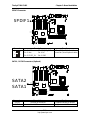
SPDIF1 Connector
S2495
CPU
USB3
1
1
1
1
1
1
1
1
1
1
1
KB1
USB1
COM1
COM2
LPT1
FAN1
ATX1
USB2
AUD2
CD1
AUX1
AUD1
ALC650
SPDIF1
FAN3
JCK1
JCK2
VT6103
AGP1
W83697HF
GAME1
BIOS
WOL
FAN2
VIA KT400
VT8377
VIA
VT8235
PCI1PCI2
PCI3
PCI4
PCI5PCI6
SATA2
SATA1
FDD
LED2
CMOS
BAT1
(Optional)
(Optional)
HPT372N
(Optional)
SII3112
(Optional)
(Optional)
(Optional)
PRI-IDE
SEC-IDE
RAID IDE2
RAID IDE1
J1
LED1
DIMM1
DIMM2
DIMM3
SPDIF1
Connector Description Functions
1
5
2
6
Pin 1: VCC
Pin 3: Non
Pin 5: SPDIF_IN
Pin 2: SPDIF_OUT
Pin 4: NC
Pin 6: GND
Sony/Philips Digital InterFace
connector (via an optional cable)
SATA1 / SATA2 Connectors (Optional)
S2495
CPU
USB3
1
1
1
1
1
1
1
1
1
1
1
KB1
USB1
COM1
COM2
LPT1
FAN1
ATX1
USB2
AUD2
CD1
AUX1
AUD1
ALC650
SPDIF1
FAN3
JCK1
JCK2
VT6103
AGP1
W83697HF
GAME1
BIOS
WOL
FAN2
VIA KT400
VT8377
VIA
VT8235
PCI1PCI2PCI3PCI4PCI5PCI6
SATA2
SATA1
FDD
LED2
CMOS
BAT1
(Optional)
(Optional)
HPT372N
(Optional)
SII3112
(Optional)
(Optional)
(Optional)
PRI-IDE
SEC-IDE
RAID IDE2
RAID IDE1
J1
LED1
DIMM1
DIMM2
DIMM3
SATA2
SATA1
Connector
Description Functions
SATA1 Serial ATA connector Supports serial ATA devices
SATA2 Serial ATA connector Supports serial ATA devices

Trinity KT400 S2495 Chapter 2: Board Installation
2-12
http://www.tyan.com
RAID IDE1 / RAID IDE2 Connectors (Optional)
S2495
CPU
USB3
1
1
1
1
1
1
1
1
1
1
1
KB1
USB1
COM1
COM2
LPT1
FAN1
ATX1
USB2
AUD2
CD1
AUX1
AUD1
ALC650
SPDIF1
FAN3
JCK1
JCK2
VT6103
AGP1
W83697HF
GAME1
BIOS
WOL
FAN2
VIA KT400
VT8377
VIA
VT8235
PCI1PCI2
PCI3
PCI4
PCI5PCI6
SATA2
SATA1
FDD
LED2
CMOS
BAT1
(Optional)
(Optional)
HPT372N
(Optional)
SII3112
(Optional)
(Optional)
(Optional)
PRI-IDE
SEC-IDE
RAID IDE2
RAID IDE1
J1
LED1
DIMM1
DIMM2
DIMM3
RAID IDE2
RAID IDE1
Connector
Description Functions
RAID IDE1
IDE RAID connector Supports IDE RAID 0, 1, 0+1
RAID IDE2
IDE RAID connector Supports IDE RAID 0, 1, 0+1

Trinity KT400 S2495 Chapter 2: Board Installation
2-13
http://www.tyan.com
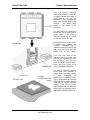
2.5 – Mounting the Motherboard
Before installing your motherboard, make sure your chassis has the necessary motherboard
support studs installed. These studs are usually metal and are gold in color. Usually, the
chassis manufacturer will pre-install the support studs. If you’re unsure of stud placement,
simply lay the motherboard inside the chassis and align the screw holes of the motherboard to
the studs inside the case. If there are any studs missing, you will know right away since the
motherboard will not be able to be securely installed.
Some chassis’ include plastic studs instead of metal. Although the plastic studs are usable,
TYAN recommends using metal studs with screws that will fasten the motherboard more
securely in place.
- Memory Type: The S2495 Trinity KT400 supports Registered, unbuffered non-ECC type
memory modules.
- CPU Front-Side Bus Speed Match: When the CPU FSB is 333MHz, you must to use
DDR333 (PC2700) memory modules.
Below is a chart detailing what the most common motherboard studs look like and how they
should be installed it.
TIP: Use metal studs if possible, as they hold the motherboard into place more securely than
plastic standoffs.

Trinity KT400 S2495 Chapter 2: Board Installation
2-14
http://www.tyan.com
2.6 – Installing the Memory
Before attempting to install any memory, make sure that the memory you have is compatible
with the motherboard as well as the processor. For example, while PC1600 DDR modules are
compatible with all DDR based motherboards, they will not work if you are required to run the
motherboard and processor buses at 133MHz. For this, PC2100 DDR modules are required.
Critically important is whether you’re using the recommended memory for the current board
you have. For this information, please check TYAN’s web site at: www.tyan.com
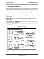
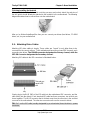
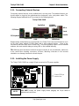
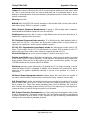
The following diagram shows the types of RAM modules you may encounter depending on
your board:
Registered DDR SDRAM
Registered
memory has
extra buffer
chips near the
bottom
DDR Unbuffered
Here are a few key points to note before installing memory into your Trinity KT400 S2495:
• 128MB, 256MB, 512MB and 1GB Registered, unbuffered non-ECC
PC1600/PC2100/PC2700/PC3200* DDR memory modules are supported
• All installed memory will be automatically detected - no need to set any jumpers
• The Trinity KT400 S2495 supports up to 3GB of memory
* NOTE: DDR400/PC3200 Qualified Memory Test List:
Vendor Type Size
ADATA winbond
W942508BH-5 256MB
PC2700 maximum to 2 DIMM support only. PC3200 maximum to 1 DIMM (DIMM 3)
support only.
Please go to TYAN website http://www.TYAN.com for the latest DDR400/PC3200
qualified memory test list.

Trinity KT400 S2495 Chapter 2: Board Installation
2-15
http://www.tyan.com
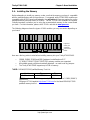
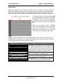
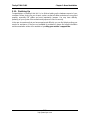
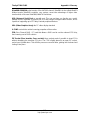
2.7 – Memory Installation Procedure
When installing memory modules, make sure the modules align properly with the memory
socket. There should be keys (small indents) on your memory modules that fit according to the
keys in the memory socket. DDR modules and sockets have only one key, which is slightly
near the center of the module/socket. SDRAM modules (also referred to as PC100 or PC133)
and their sockets have two keys and will not insert into DDR DIMM sockets. The method of
installing memory modules is detailed in the following diagrams.
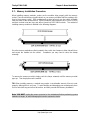
Once the memory modules are firmly seated in the socket, two clamps on either side will close
and secure the module into the socket. Sometimes you may need to close the clamps
manually.
To remove the memory module, simply push the clamps outwards until the memory module
pops up. Then simply remove the module.
TIP: When installing memory, a module may require a considerable amount of force to seat
properly, although this is very rare. To avoid bending and damaging your motherboard, place
it on its anti-static bag and onto a flat surface, and then proceed with memory installation.
Note: YOU MUST unplug the power connector to the motherboard before performing system
hardware changes, to avoid damaging the board or expansion device
Page is loading ...
Page is loading ...
Page is loading ...
Page is loading ...
Page is loading ...
Page is loading ...
Page is loading ...
Page is loading ...
Page is loading ...
Page is loading ...
Page is loading ...
Page is loading ...
Page is loading ...
Page is loading ...
Page is loading ...
Page is loading ...
Page is loading ...
Page is loading ...
Page is loading ...
Page is loading ...
Page is loading ...
Page is loading ...
Page is loading ...
Page is loading ...
Page is loading ...
Page is loading ...
Page is loading ...
Page is loading ...
Page is loading ...
Page is loading ...
Page is loading ...
Page is loading ...
Page is loading ...
Page is loading ...
Page is loading ...
Page is loading ...
Page is loading ...
Page is loading ...
Page is loading ...
Page is loading ...
Page is loading ...
Page is loading ...
Page is loading ...
Page is loading ...
Page is loading ...
Page is loading ...
Page is loading ...
Page is loading ...
Page is loading ...
Page is loading ...
Page is loading ...
Page is loading ...
-
 1
1
-
 2
2
-
 3
3
-
 4
4
-
 5
5
-
 6
6
-
 7
7
-
 8
8
-
 9
9
-
 10
10
-
 11
11
-
 12
12
-
 13
13
-
 14
14
-
 15
15
-
 16
16
-
 17
17
-
 18
18
-
 19
19
-
 20
20
-
 21
21
-
 22
22
-
 23
23
-
 24
24
-
 25
25
-
 26
26
-
 27
27
-
 28
28
-
 29
29
-
 30
30
-
 31
31
-
 32
32
-
 33
33
-
 34
34
-
 35
35
-
 36
36
-
 37
37
-
 38
38
-
 39
39
-
 40
40
-
 41
41
-
 42
42
-
 43
43
-
 44
44
-
 45
45
-
 46
46
-
 47
47
-
 48
48
-
 49
49
-
 50
50
-
 51
51
-
 52
52
-
 53
53
-
 54
54
-
 55
55
-
 56
56
-
 57
57
-
 58
58
-
 59
59
-
 60
60
-
 61
61
-
 62
62
-
 63
63
-
 64
64
-
 65
65
-
 66
66
-
 67
67
-
 68
68
-
 69
69
-
 70
70
-
 71
71
-
 72
72


Tyan Trinity KT400 S2495 User manual
- Type
- User manual
- This manual is also suitable for
Ask a question and I''ll find the answer in the document
Finding information in a document is now easier with AI
Related papers
-
Tyan Trinity i845GL S2098 User manual
-
-
-
-
-
Tyan S2662 User manual
-
Tyan Computer S1854 Trinity 400 User manual
-
-
-
Other documents
-
BCM BC133KT-100 User manual
-
-
 WinFast NF4K8AB User manual
-
-
Acrosser Technology AR-B8172 Owner's manual
-
VTech ATI A3 + ALI M1535D+ Technical Reference Booklet
-
 StarTech.com UNIMEMHS Datasheet
-
PC CHIPS P13G+ (V1.0) User guide
-
Korg Trinity User manual
-
Compaq Mega-Post User manual

