Page is loading ...

Tyan S1834
Tiger 133
Motherboard User’s Manual
Revision 1.20
Copyright © Tyan Computer Corporation, 2000. All rights reserved. No part of this
manual may be reproduced or translated without prior written consent from Tyan
Computer Corp.
All registered and unregistered trademarks and company names contained in this
manual are property of their respective companies including, but not limited to the
following.
Award is a trademark of Phoenix Technologies Ltd.
Windows is a trademark of Microsoft Corporation.
IBM, PC, AT, PS/2 are trademarks of IBM Corporation.
INTEL, Pentium II/ III, Celeron are trademarks of Intel Corporation.
S1834 Tiger 133 are trademarks of TYAN Computer Corporation.
Information contained in this publication has been carefully checked for accuracy and
reliability. In no event will Tyan Computer be held liable for any direct or indirect,
incidental or consequential damage, loss of use, loss of data, or other malady resulting
from errors or inaccuracies of information contained in this manual. The information
contained in this document is subject to change without notice.
PRINTED IN TAIWAN

Table of Contents
1. Introduction.................................................................................................. 4
Overview.............................................................................................4
Icons................................................................................................... 5
Hardware Specifications/Feaures.................................................. 6
Technical Support..............................................................................8
Returning Merchandise for Service................................................8
2. Board Installation........................................................................................ 9
Unpacking..........................................................................................9
Installation..........................................................................................9
Quick Reference for Jumpers........................................................ 11
Map of Motherboard Jumpers..................................................... 12
Setting Jumpers............................................................................ 14
Clear CMOS & Reset Password .................................................. 15
Soft Power Connector.................................................................... 16
Hardware Reset Switch Connector Installation......................... 16
Chassis Intrusion Alarm Connector............................................ 16
Power LED Connector.................................................................... 16
CMOS RTC...................................................................................... 16
Flash EEPROM................................................................................ 17
Mounting the Motherboard in the Chassis ...............................17
Installing Memory........................................................................... 17
Installing the CPU and Cooling Fan............................................ 21
Connecting IDE and Floppy Drives............................................. 24
Installing Add on Cards ............................................................... 26
Connecting PS/2, USB, Serial and Parallel Devices................... 26
Connecting the Power Supply...................................................... 28
3. BIOS Configuration..................................................................................29
Main Setup Menu........................................................................... 32
Standard CMOS Setup................................................................... 34
Advanced BIOS Features setup................................................... 39
Advanced Chipset Features Setup...............................................44
Intergrated Peripherals....................................................................48
Power Management Setup............................................................ 52
PnP/PCI Configuration ...................................................................57
Flash Writer Utility...........................................................................59

4. System Resources......................................................................................62
Beep Codes..................................................................................... 62
Appendix Glossary..........................................................................................63
Compliance Information................................................................................70

http://www.tyan.com
4
Chapter 1
Introduction
Overview
The S1834 Tiger 133 is a quality, high performance motherboard designed for
dual Intel PII / PIII microprocessors. The Tiger 133 utilizes the VIA Apollo Pro
133A chipset (VT82C694X) with Award BIOS. The S1834 can support CPU
speeds of 450MHz through 800+MHz, and host bus speeds of 100 MHz to 133
MHz (the VIA chipset’s bus speed is Auto-Determined by the CPU). The S1834
motherboard, with built-in 4x AGP slot, provides high performance capabilities
that are ideal for a wide range of demanding applications such as CAD, CAM,
CAE, desktop publishing, 3D animation, 3D Games and video production.
This system board in an ATX form factor offers far more features and
expandability than other ATX models. Some of the features included are
onboard dual channel PCI PIO, Bus Master IDE and UltraDMA/66, onboard
floppy controller, and onboard high speed I/O, PC133 SDRAM support, and
Virtual Channel Memory SDRAM support.
Flexibility and expandability have been designed into the Tiger 133. With I/O
and drive controller support built onboard, the one AGP slot plus six PCI gives
a total of seven usable slots for numerous add-on expansion cards. Remember
to visit TYAN Computer’s web site located at http://www.tyan.com. There you
can find information on all of TYAN’s products along with FAQs, distributors
list, and drivers.
chapter 1
Introduction

S1834 Tiger 133
5
INTRO
Icons
In order to help you navigate this manual and set up your system, we have
added several icons to our format.
This icon alerts you to particularly important details regarding the
setup or maintenance of your system. This icon often appears next
to information that may keep you from damaging your board or
system. While we will often point out the most vital paragraphs in a
chapter, you should always read every word in the text. Failing to do so can
lead to exasperation and expense.
Wherever possible, we have included step-by-step instructions for
setting up your system, which are indicated by this icon. However, it
is in your best interest to read an entire section (and perhaps the
entire manual) before you begin to install your motherboard.
While we have alerted you to potential dangers in several places in
the manual with this icon, these warnings should not be regarded as
the whole of your safety regimen. Never forget that computers are
electrical devices, and are capable of delivering a shock. Prevent
damage to yourself and to your board: always ensure that your system is
turned off and unplugged whenever you are working with it, and that you are
equipped with a static safety device.
!!
!!
!
important!
procedure
1.
2.
3.
warning

http://www.tyan.com
6
Hardware Specifications/Features
Processor Information • Two SECC/SECC2 slots (Slot One type)
• 100MHz and 133MHz bus support
• Pentium II or Pentium III 450-800MHz*
• Two onboard VRMs (VRM 8.4 spec)
• Auto detect CPU Core Voltage
Chipset Information • VIA Apollo Pro 133A Chipset
(VT82C694X & VT82C596B)
• Winbond W83977ATF Super I/O chip
BIOS Information • Award BIOS 2Mbit Flash RAM
• APM 1.2 & ACPI 1.0
• User settings of HW monitoring
• Auto configuration of IDE hard disk types
• Multiple boot options
• DMI 2.0 compliant
Main Memory • Four 168-pin 3.3V DIMM sockets
• Supports up to 2 GB at 100 MHz
• Supports up to 1.5 GB at 133 MHz
• Supports PC100 / PC133 SDRAM
Expansion Slots • One 2x / 4x AGP v.2.0 slot
• Six 32-bit PCI v.2.2 compliant slots
• One ISA slot (shared w/ a PCI slot)
• Seven total usable slots
Integrated PCI IDE • Two 40-pin IDE connectors for up to 4
drives
• UltraDMA33/66 supported
• ATAPI IDE CD-ROM and LS-120
supported
* See TYAN website for CPU Compatibility List: www.tyan.com
Chapter 1
Introduction

S1834 Tiger 133
7
Integrated I/O • One Floppy connector for up to 2 drives
(1.44 MB, 2.88 MB, 3-mode)
• Two 9-pin 16550 UART Serial ports
• One 25-pin ECP/EPP Parallel port
• Two USB ports
• PS/2 Mouse & Keyboard ports
Hardware Monitoring
• •
• •
• Hardware monitoring chip
••
••
• 3-pin Fan monitoring headers
••
••
• 2-pin chassis Intrusion header
• Temperature and Voltage monitoring
• 3-pin Wake on Modem header
Form Factor • ATX Footprint (12” x 9.6”)
• Stacked Mouse / Keyboard ports
• Stacked two USB ports
• Stacked two Serial & one Parellel ports
Regulatory • FCC Class B (Declaration of Conformity)
• European Community CE (Declaration of
Conformity)
Software Specifications
OS •Operates with MS-DOS ver 6.22, Windows 98
& Win98 SE, Windows NT 4.0, Novell 5.0
Windows 2000(RC3) pending, SCO Unix 5.01
Linux 6.0
Please refer to http://www.tyan.com for OS
updates
INTRO

http://www.tyan.com
8
Chapter 1
Introduction
Technical Support
If a problem arises with your system, you should turn to your dealer for help
first. Your system has most likely been configured by them, and they should
have the best idea of what hardware and software your system contains.
Hence, they should be of the most assistance. Further, if you purchased your
system from a dealer near you, you can actually bring your system in to them
to have it serviced, instead of attempting to do so yourself (which can have
expensive consequences). Please refer to your dealer for specific warranty
coverage details.
Help resources:
1. See FAQ and beep codes sections of this manual.
2. See Tyan web site for FAQ, bulletins, driver updates, etc.
http://www.tyan.com
3. Contact your dealer or distributor for help BEFORE calling Tyan.
4. Check the Tyan user group: alt.comp.periphs.mainboard.tyan
Returning Merchandise for Service
During the warranty period, contact your distributor or system vendor FIRST
for any product problems. This warranty only covers normal customer use and
does not cover damages incurred during shipping or failure due to the
alteration, misuse, abuse, or improper maintenance of products.
For Resellers Only:
A receipt or copy of your invoice marked with the date of purchase is required
before any warranty service can be rendered. You can obtain service by calling
the manufacturer for a Return Merchandise Authorization (RMA) number. The
RMA number should be prominently displayed on the outside of the shipping
carton and the package should be mailed prepaid, or hand-carried to the
manufacturer. TYAN will pay to have the board shipped back to you.

S1834 Tiger 133
9
chapter 2
Board Installation
Unpacking
The motherboard package should contain the following:
(1) S1834 mainboard
(1) 34-pin floppy cable pack
(1) 80-pin ATA-66 IDE cable
(1) S1834 User’s Manual
(1) Driver CD
(2) URM Retention Modules
(Terminator card is currently not needed on this board when using only a
single processor. Check http://www.tyan.com for information and updates
concerning CPUs.)
Installation
You are now ready to install your motherboard. The mounting hole pattern of
the S1834 matches the ATX system board specifications. Your chassis should
support a standard ATX mainboard form factor.
How to install our products right...the first time.
What’s the first thing I should do?
The first thing you should do is read this user’s manual. It contains important
information which will make configuration and setup much easier.
Here are some precautions you should follow when installing your mother-

http://www.tyan.com
10
Chapter 2
Board Installation
procedure
1.
2.
3.
board:
(1) Ground yourself properly before removing your motherboard
from the antistatic bag. Unplug the power from your computer
and then touch any metal part on the computer case. (Or wear a
grounded wrist strap.)
(2) Hold the motherboard by its edges and do not touch the bottom of
the board.
(3) Avoid touching motherboard components, IC chips, connectors,
and leads.
(4) Avoid touching pins of memory modules and chips.
(5) Place motherboard on a grounded antistatic surface or on the
antistatic bag.
Having reviewed the precautions above, the next step is to take the mother-
board out of the cardboard box and static bag, hold it by its edges, and place it
on a grounded antistatic surface, component side up. Inspect the board for
damage.
DO NOT APPLY POWER TO THE BOARD IF IT HAS BEEN DAMAGED!
Press down on any of the socket ICs if it appears that they are not properly
seated (the board should still be on an antistatic mat). Do not touch the bottom
of the board. Remember, don’t take any electronic device out of its protective
bag until you are ready to actually install it into the computer case. If you do
not ground yourself, you risk zapping the motherboard or adapter card.
Subsequent problems may not arise immediately because electrostatic dis-
charge damage, unlike physical damage, causes the device to fail over time.
Installation Steps
1. Set Jumpers
2. Mount Motherboard in Chassis
3. Install Memory
4. Install CPU & Cooling Fan
5. Connect IDE and Floppy Drives
6. Connect Power Supply
7. Install Add-on Cards
8. Connect PS/2, USB, Serial and Parallel Devices
!!
!!
!
important!

S1834 Tiger 133
11
Quick References for Jumpers
In this manual, the terms “closed” and “on” are used when referring to jumpers
(or jumper pins) that are active; “open” and “off” are used when referring to
jumpers (or jumper pins) that are inactive. See the Figure 2-1 for examples of
“on” and “off” pins and jumpers.
Jumpers and pins are connected by slipping the plastic jumper connector
overtop of two adjacent jumper pins (indicated by 1-2 or 2-3). The metal rod
inside the plastic shell bridges the gap between the two pins, completing the
circuit. See Figure 2-2 for more example of pin connections.
Figure 2-1 Figure 2-2
The tables and maps on the following pages will help you set the jumpers for
CPU speed, Infrared, and external connector pin assignments, among others.
The miniature motherboard maps will help you locate the jumpers on your board.
A full-page map of the motherboard can be found on the next two pages.
2 pin jumpers
off on
3 (or more) pin jumpers
1-2 2-3 open
1
2
3
1
2
3
1
2
3
INSTALL

http://www.tyan.com
12
Chapter 2
Board Installation
The tiny “1”s next to jumpers of 3 pins or more indicate the position of pin 1
for that jumper.
Figure 2-3 : Map of Motherboard Jumpers
USB1
Keyboard
USB0
Mouse
Primary IDE connector
COM2 COM1
Printer Port
PCI slot 2
PCI slot 3
AGP port
PCI slot 4
PCI slot 5
PCI slot 6
Flash BIOS
PCI slot 1
Secondary IDE connector
Floppy drive connector
1
1
J8 (WOR)
J9 (WOL)
1
ATX power connector
1
1
VIA
VT82C694X
FAN6
1
DIMM bank 3
DIMM bank 4
DIMM bank 2
FAN4
1
Slot 1 Type CPU
FAN1
1
VIA
VT82C596B
ISA slot
Slot 1 Type CPU
DIMM bank 1
1
JP4
JP5
JP6
JP7
FAN3
FAN5
FAN2
J10
JP10
Clear CMOS
J11
Winbond
1
1
3 volt
lithium
battery
1
1
1
JP14

S1834 Tiger 133
13
Figure 2-4 : Map of S1834 Features
VIA Apollo Pro
133A Chipset
4 DIMM slots
2 SECC slots
Award BIOS
1 ISA slot
6 PCI slots
AGP port
IDE and Floppy
connectors
Double row ATX connectors
ATX Power supply
connectors
INSTALL

http://www.tyan.com
14
Chapter 2
Board Installation
1. Setting Jumpers
1-A. CPU Speed Settings (Jumpers JP4, JP5, JP6, JP7)
There are two steps to set the CPU speed. First, set the clock multiplier with
jumpers JP4 -7 according to the specification of your CPU using the chart
below. After the system is ready to boot the BUS Speed is auto-detected.
Presently all Celeron CPUs use a 66MHz bus speed. (Tyan does not recom-
mend operating CPUs, memory, or PCI Bus at higher than rated speed. Tyan
takes no responsibility for any problems related to overclocking any bus or
component on the system board.)
JP4, JP5,
JP6, JP7
!!
!!
!
important!
M ultiplie r Bus Spe e d
(set Jmprs
on board)
(Auto-
Detected)
100 350
133 467
100 400
133 533
66 300
100 450
133 600
66 333
100 500
133 667
66 366
100 550
133 733
66 400
100 600
133 800
66 433
100 650
133 866
66 466
100 700
133 933
66 500
100 750
133 997
66 533
100 800
133 1064
OFF8 OFF ON ON
OFF
7.5 ON OFF OFF OFF
7ONOFFON
OFF
6.5 ON ON OFF OFF
6ONONON
ON
5.5 OFF OFF OFF ON
5OFFOFFON
ON
4.5 OFF ON OFF ON
4 OFF ON ON
JP7
3.5 ON OFF OFF ON
CPU speed JP4 JP5 JP6

S1834 Tiger 133
15
1-B. Panel Connector Settings (Jumper J10)
Power LED:
For 2-pin: bicolor/single
color - Use pins 2-4
1-C. Wake-On LAN (J9)
1-D. Wake-On Ring (J8)
1-E. Clear CMOS and Reset Password (JP10)
If you have been locked out of your system because you forgot your password
or set the CMOS incorrectly, follow the instructions below.
1. Power off the system, UNPLUG POWER CONNECTOR
2. Set jumper JP10 to pins 2 and 3
3. Wait for 2 seconds, then return jumper JP10 to pins 1 and 2.
4. Power on the system again.
By following this procedure, you will erase your password and reset the CMOS
to the BIOS defaults.
tluafeDteseR
01PJ
2-13-2
Top
Bottom
J10
2 4 6 8 10 12 14 16 18
1 3 5 7 9 11 13 15 17
LED + 1 2 LED Green
LED - 3 4 LED Yellow
Ground 5 6 Power On/Off
Re s e t 7 8 Gro u n d
VC C 9 10 N C .
IRRX 11 12 Power +5V
Ground 13 14 N.C
IRTX 15 16 N.C
RESV 17 18 Speaker
Infrared
HDD
LED
Pwr/Slp
LEDs
Reset
Switch
Power
(Sleep)
Switch
!!
!!
!
important!
INSTALL

http://www.tyan.com
16
Chapter 2
Board Installation
1-F. Soft Power Connector
The Soft Power Connector is part of jumper block J10. The Tiger 133 uses the
chipset for power management, including turning on and off the system. If the
Power Button Function option in the BIOS Power Management Menu is set to
On/Off (which is the default), pressing the power button once after the BIOS
has booted up will turn the system on and off. If the Power Button Function
option is set to Suspend, pressing the power button once will wake the system
or send it to Suspend mode. In this case, you cannot turn the system off
unless you shut down through the Windows operating system or you hold the
power button down for four seconds.
1-G. Hardware Reset Switch Connector Installation
The Reset switch on your case’s display panel provides you with the Hard-
ware Reset function, which is the same as power on/off. The system will do a
cold start after the Reset button is pushed. (J10 pin 5 & 7 for example).
1-H. Chassis Intrusion Alarm Connector (JP14)
The JP14 connector is an intrusion alarm that can be connected to the system
chassis. When active (JP14 is connected to the chassis), this alarm will alert
the system administrator anytime someone opens the system’s case.
1-I. Power LED Connector
Refer to panel connector J10 for 2 pin
LEDs. 3 pin LED’s can still be used on
J10 where pin 13 would be for the
Ground pin.
1-J. Server Management Connector
(J11)
J11 is reserved for server management
hardware connection.
CMOS RTC
The Real Time Clock (RTC) circuit, which provides the date and time for the
system is integrated into the Via Apollo Pro Plus 133A AGPset. If the external
battery for the RTC is low, it will prevent your system from POSTing, and you
will not get a display. Normally the life span of an external battery is 2 years. If
yours is running low, you will need to replace it with a new 3V lithium battery
(Sony CR2032).
J8 (WOR)
J9 (WOL)
JP10
(Clr CMOS)
J10,
JP14
J11

S1834 Tiger 133
17
Flash EEPROM
The Tiger 133 uses flash memory to store BIOS firmware. It can be updated as
new versions of the BIOS become available. You can upgrade your BIOS easily
using the flash utility (see page 59).
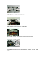
2. Mounting the Motherboard in the Chassis
Follow the instructions provided by the case manufacturer for proper installa-
tion guidelines. TYAN recommends that you use screw down the motherboard.
with all the mounting holes provided. If your case does not have a hole for a
standoff, simply cut off the bottom of the plastic standoff so that the flat
portion rests on the metal. The adapter cards and the screws holding them
down will keep your board flat. The fastening screw should not short any of
the traces on the motherboard. Make certain that you do not overtighten the
screw, as it will damage the motherboard and possibly break internal traces in
the surrounding area. The hole you should use is located at the top-center of
the board where the adapter cards are fastened to the case.
3. Installing Memory
Since TYAN boards are manufactured with performance in mind, you should
use add-in components that match. It is highly recommended that the memory
DIMMs are installed prior to connecting the power supply. Some DIMM
modules may seem to be high quality because of name or feel but that does not
guarantee real-world usability. Some cheaper or OEM memory may have brand-
name components, but they may contain inferior or substandard parts which
do not meet the critical tolerances our products require. Because of this, your
memory may not work correctly in a TYAN board though it may work well in a
competitor’s board. This is because many of our competitors do not adhere to
the strict tolerances required for high performance. If you buy a TYAN board,
you are getting the best system available. To make installation easy and
trouble free, get high quality parts. Some brands we recommend are Advantage
Memory, Corsair Microsystems, Millenium, Kingston Memory, QesTec
Incorporated, Unigen, Micron Technology, and Crucial Technology. These
DIMMs have proven to be very stable on our boards and perform extremely
well. Please check the TYAN website for more information and updates about
memory compatibility: www.tyan.com
!!
!!
!
important!
INSTALL

http://www.tyan.com
18
Chapter 2
Board Installation
This motherboard operates on a 3.3 volt standby for the DIMM banks .
Because of this, you need to UNPLUG the AC power cord before installing
your DIMM memory modules. Otherwise, the motherboard may automatically
power up when the memory is inserted into the slot.
Figure 2-5*
*Note: The image above is used to illustrate a concept and may not represent the actual
image of your motherboard.
To install your DIMMs, line your module up so that the pins fit into the slot.
There is only one way that your DIMM can fit properly. Make sure that the
short row of pins is lined up with the short gap in the DIMM slot. Figure 2-5
shows how to sit the DIMM into its slot. To insert the DIMM, push down
vertically on the module with even force, as shown in the photo. Do not shove
one end in first; doing so will bend the DIMM pins.
To lock the DIMM into place, push the plastic clips on either end of the slot
onto the notches in the ends of the DIMM (see Figure 2-6 on the next page).
To remove your DIMM, simply pull the clips back, and pull up on the module.
Place the DIMMs in an anti-static bag as soon as you remove them to avoid
static damage.
warning

S1834 Tiger 133
19
Figure 2-6*
*Note: The image above is used to illustrate a concept and may not represent the actual
image of your motherboard.
The Tiger 133 uses a 64-bit data path from memory to CPU and can accommo-
date up to 2 GB of PC100 SDRAM and up to 1.5GB of PC133 SDRAM. The
168-pin DIMMs (Dual In-line Memory Modules) must be of the 3.3V,
unbuffered, non-ECC variety. The position of the notch in the SDRAM key
position will tell you whether or not a DIMM is unbuffered (see the Figure 2-7
below). All installed memory will be automatically detected, so there is no
need to set any jumpers.
Figure 2-7
Some details of memory installation:
• At least one unbuffered DIMM must be installed for the system to POST.
• The mainboard supports 32MB, 64MB, 128MB and 256MB SDRAM.
• PC-100 DIMM is required if CPU bus speed is at 100MHz
RFU
Buffered
Unbuffered
168-pin DIMM
INSTALL

http://www.tyan.com
20
Chapter 2
Board Installation
The table below shows some of the possible memory configurations. Not all
possible configurations are listed.
*1.5GB memory capacity applies only to PC133 SDRAM.
1knaBMMID2knaBMMID3knaBMMID4knaBMMIDlatoT
1xBM8000BM8
1xBM81xBM800BM61
1xBM81xBM81xBM80BM42
1xBM611xBM81xBM80BM23
1xBM611xBM611xBM80BM04
1xBM611xBM611xBM610BM84
1xBM231xBM611xBM610BM46
1xBM231xBM231xBM610BM08
1xBM231xBM231xBM230BM69
1xBM461xBM4600BM821
1xBM821000BM821
1xBM821
0
1xBM821
0
BM652
1xBM8211xBM8211xBM8210BM483
1xBM8211xBM8211xBM8211xBM821BM215
1xBM652
0
1xBM652
0
BM215
1xBM6521xBM6521xBM6520BM867
1xBM6521xBM6521xBM6521xBM652BM4201
1xBM2151xBM2151xBM215
0
*BG5.1
/