Majestic CVR36 User manual

Category
Fireplaces
Type
User manual
STR/CVR Series
Woodburning Fireplace
For Models:
STR33
STR36
STR42
CVR36
CVR42
For use in U.S./Canada
Underwriter's Laboratories
Report No. MH6018
DO NOT DISCARD THIS MANUAL: Retain for future use.
7412961 3/06 Rev. 15
Homeowner's Installation
and Operating Manual
2
STR/CVR Series Woodburning Fireplaces
7412961
Safety Information
PLEASE READ THIS MANUAL BEFORE INSTALLING AND USING FIREPLACE.
IMPORTANT:
Read all instructions and warnings carefully before starting installation. Failure to
follow these instructions may result in a possible fire hazard and will void the warranty.
Description
The STR/CVR Series fireplaces are multi-side solid fuel,
woodburning fireplaces. These are radiant models only
and include a preinstalled outside air kit.
Precautions
Majestic Fireplaces and component parts have been
highly tested and will operate safely when installed in
accordance with instructions provided in this manual.
Carefully read and understand all instructions before
beginning installation.
If you notice any damage to fireplace or component parts,
immediately report damage to your Majestic Fireplaces
dealer.
Only use CFM Corporation components or the warranty
will be voided and a fire hazard may be created.
CFM Corporation warranty will be voided by and CFM
Corporation disclaims any responsibility for the following
actions:
Installation of any damaged fireplace or chim-
ney component;
Modification of fireplace, chimney assembly or
any component parts thereof; (except for chase
flashings as detailed in the Chimney Top instal-
lation instructions).
Installation other than as instructed by CFM
Corporation; or
Installation and/or use of any component part
not manufactured or approved by CFM Corpo-
ration in combination or assembly with a Majes-
tic Fireplaces fireplace system, notwithstanding
any independent testing laboratory or other
third party approval of such component parts
or accessory.
Any such action may possibly cause a fire hazard.
Consult local building codes to ensure that you are in
compliance before installing the fireplace.
Fireplaces must be vented to the out-of-doors.
Do not obstruct or modify air inlets/outlets in any
manner.
Do not install combustible materials on any of the
black fireplace surround.
Burn only solid wood fuel or gas logs.
Do not install a solid fuel burning insert or other
products not specified for use with this fireplace.
Proposition 65 Warning: Fuels used in gas, wood-
burning or oil fired appliances, and the products of
combustion of such fuels, contain chemicals known to
the State of California to cause cancer, birth defects
and other reproductive harm.
California Health & Safety Code Sec. 25249.6
WARNING: Check with your electronics manufac-
turer before installing a television or other electronic
device above this fireplace.D
Drafts
The fireplace should not be located in areas that create
drafts (ie: frequently opened doors and central heating air
inlets/outlets) that hamper the normal flow of air into the
fire.
Gas Logs
If you plan to install a gas log, the gas line should be
installed before framing the fireplace. The gas line must
be installed by a certified gas line installer.
STR33 / STR36 / STR42
CVR36 / CVR42
Listed
UL 127 / ULC-S610
Standard for Factory Built Fireplaces
Safety Information . . . . . . . . . . . . . . . . . . 2
Specifications and Framing
. . . . . . . . . . 3
Parts Identification
. . . . . . . . . . . . . . . . . 4
Chimney Requirements . . . . . . . . . . . . . 6
Planning Information . . . . . . . . . . . . . . . . 7
Installation . . . . . . . . . . . . . . . . . . . . . . . 8
Replacement Parts . . . . . . . . . . . . . . . . 20
Accessories . . . . . . . . . . . . . . . . . . . . . 22
Table of Contents
Units: EC20R0, FC20R0, GC20R0, FD20R0, GD20R0
3
STR/CVR Series Woodburning Fireplaces
7412961
STR Series Woodburning Fireplace
Fig. 1 STR Series specifications and framing.
12"
9"
A
D
E
36"
21"
37"
7"
7"
Gas Line Access
FP702A
STR SPECS
9/24/98
added note 9/21/99
Outside
Air
14"
12"
C
12"
G
F
B
J
24" Total
Unit Width
Framing Width
Will be 24" Minus
2 x (Drywall Thickness)
18"
STR33 STR36 STR42
A 33" 36" 42"
838mm 914mm 1067mm
B 37" 40" 46"
940mm 1016mm 1168mm
C 18" 20" 23"
470mm 508mm 584mm
D 49" 49" 53"
1267mm 1267mm 1368mm
E 52" 52" 56"
1340mm 1340mm 1442mm
F 11" 11" 13"
279mm 279mm 343mm
G 8" 8" 11"
203mm 203mm 279mm
J 26" 29 " 35"
680mm 741mm 894mm
Fig. 2 CVR Series specifications and framing.
CVR Series Woodburning Fireplace
"
"
B
A
D
E
36"
"
37"

"

"
Gas Line
Access
FP703A
CVR specs
8/4/98
9/28/99 added note djt
" Total
Unit Width
"
G
F
C
Outside
Air
"
"
J
Framing Width
Will be 24" 
2 x (Drywall Thickness)
18"
CVR36 CVR42
A 36" 42"
914 mm 1067 mm
B 40" 46"
1016 mm 1168 mm
C 20" 23"
508 mm 584 mm
D 49" 53"
1267 mm 1368 mm
E 52" 56"
1340 mm 1442 mm
F 11" 13"
280 mm 340 mm
G 8" 11"
203 mm 280 mm
J 29" 35"
741 mm 895 mm
4
STR/CVR Series Woodburning Fireplaces
7412961
FP701
STR/CVR Series Woodburning Fireplace
Fig. 3 STR/CVR Parts Identification.
FP701
STR/CVR Parts ID
5/18/98
STR Fireplace
CVR Fireplace
Gas Line
Access
Outer
Dome
Outside Air Access
Ledge
Brackets
Header
Standoffs
Flue Damper
Control
(Inside)
Flue
Damper
Flue
Collar
Outer Collar
Screen
Gas Line
Knock-out
(Both Sides)
Brick liner on
Sides and Hearth
Air Inlet
Hearth
Wood Grate
Firebox
Metal Safety Strips,
shown not in place
(1, 2, or 3 Pieces)
Outside Air
Control
Outer
Dome
A
B
FP1545
hearth dimensions
1/05
Front/Back Width Side Width
A B
STR33 26" 17¹⁄₈"
(660 mm) (435 mm)
STR/CVR36 29" 17¹⁄₈"
(737 mm) (435 mm)
STR/CVR42 35" 17
¹⁄₈"
(889 mm) (435 mm)
FP1545
Fig. 3a Hearth dimensions.
5
STR/CVR Series Woodburning Fireplaces
7412961
Chase Installation
Insulation methods shown are optional
for cold climate, not a requirement for
unit operation.
FP704
Fig. 4 Fireplace and chase parts identification.
FP704
STR (from FP528)
7/28/98
Termination Cap
Storm Collar
Pan Flashing
Draftstop
Finish Wall
Batt Insulation
(cut out around
firestop)
Firestop
Ceiling Level
Outer Dome
Refer to Figures 21
and 26 for clearance
information.
Ledge Brackets
Nailing Flange
Gas Access
(both sides)
Outside Air Cover Plate
Surround
Screen
Grate
Firebox
Outside Air
Control
6
STR/CVR Series Woodburning Fireplaces
7412961
Chimney Requirements - Offset Installations
0 0 0 0 0 3" 11"
1 0 0 0 0 8
¹⁄₄" 20"
0 1 0 0 0 11
¹⁄₄" 25¹⁄₄"
2 0 0 0 0 13
¹⁄₂" 29¹⁄₄"
1 1 0 0 0 16
¹⁄₂" 34¹⁄₄"
0 0 1 0 0 20
¹⁄₄" 40³⁄₄"
2 1 0 0 0 21
³⁄₄" 43¹⁄₂"
0 0 0 1 0 26
¹⁄₄" 51¹⁄₄"
0 1 1 0 0 28
¹⁄₂" 55¹⁄₄"
1 0 0 1 0 31
¹⁄₂" 60¹⁄₄
0 1 0 1 0 34
¹⁄₂" 65¹⁄₂"
0 0 2 0 0 37
¹⁄₂" 70³⁄₄"
1 1 0 1 1 41
¹⁄₂" 77³⁄₄"
0 0 1 1 1 45" 83
³⁄₄"
0 1 2 0 1 47
¹⁄₄" 87¹⁄₂"
0 0 0 2 1 51" 94"
0 1 1 1 1 53
¹⁄₄" 98"
0 0 3 0 1 56
¹⁄₄" 103¹⁄₄"
0 1 0 2 1 59
¹⁄₄" 108¹⁄₂"
0 0 2 1 1 62
¹⁄₄" 113¹⁄₂"
0 1 3 0 1 64
¹⁄₂" 117¹⁄₂"
0 0 1 2 1 68
¹⁄₄" 124"
0 1 2 1 1 70
¹⁄₂" 128"
0 0 0 3 1 74
¹⁄₄" 134¹⁄₂"
0 1 1 2 2 78" 140
³⁄₄"
0 0 3 1 2 81" 146"
0 1 0 3 2 84" 151
¹⁄₄"
0 0 2 2 2 87" 156
¹⁄₂"
0 1 3 1 2 89
¹⁄₄" 160¹⁄₄"
0 0 1 3 2 93" 166
³⁄₄"
0 1 2 2 2 95
¹⁄₄" 170³⁄₄"
0 0 0 4 2 99
¹⁄₄" 177³⁄₄"
0 1 1 3 2 101
¹⁄₄" 181³⁄₄"
0 0 3 2 2 104
¹⁄₄" 186¹⁄₄"
0 1 0 4 2 107
¹⁄₄" 191¹⁄₂"
0 0 2 3 2 110
¹⁄₄" 196³⁄₄"
0 1 3 2 3 114" 203
¹⁄₄"
0 0 1 4 3 117
³⁄₄" 209³⁄₄"
0 1 2 3 3 120" 213
¹⁄₂"
0 0 0 5 3 123
³⁄₄" 220"
30˚ Elbow Offsets
1'
1¹⁄₂'
3' 4'
Chimney
Support
Offset
Rise
Notes: G + H cannot exceed 20 feet.
Air Space Clearances:
SK8 (2-wall) = 1¹⁄₂" , and 11CF (2-wall) = 2"
Illustration Key
The following safety rules apply to
offset installations (letters correspond
with illustration above):
A. Height of the chimney is measured
from the hearth to the chimney exit.
CVR / STR Series
Maximum: 90'0"
Minimum:
Without Elbows 15'6"
With 2 Elbows* 17'6"
With 4 Elbows* 21' 0"
B. Do not use more than 4 elbows per
chimney.
Attach the straps of the return (top)
elbow to a structural framing member.
The offset (first) elbow of any pair does
not have straps.
FP720
C. The chimney cannot be more than 30˚
(45˚ in Canada) from the vertical plane in
any installation*.
D. The maximum length of the angled run
of the total chimney system is 20 feet. (G
plus H cannot exceed 20 feet.)
E. A chimney support (Models TCS8A or
11CS) is required every 6 feet of angled
run of chimney. Chimney supports are re
-
quired for every 30 feet and 60 feet (SK8
& CF11 pipe) of vertical chimney height
above the hearth.
Determine the offset distance of your
chimney arrangement from the centerline
of the fireplace to the centerline of the
chimney where it is to pass through the
first ceiling.
NOTE: This offset distance may not be
your full offset distance. See Examples 2
and 3.
IWF282
MBUF
5/26/96
OFFSET
RISE
FP282
* In Canada, two (2) SK845 are allowed.
Fig. 5 Chimney system requirements.
D
RISE
B
G
H
B
OFFSET
C
E
6 FT.
G
H
A
HEARTH
FLOOR
CHIMNEY
SECTION
CHIMNEY FLUE EXIT
ELBOW
FP720
STR/CVR
6/4/98
30˚
OFFSET
ELBOW
30˚
OFFSET
ELBOW
30˚
RETURN
ELBOW
30˚
RETURN
ELBOW
SKCS8
SUPPORT
Example 1 Example 2 Example 3
7
STR/CVR Series Woodburning Fireplaces
7412961
Planning Information
Preplanning an installation is very important to ensure
safety and to save time and money. An installer must
predetermine where a fireplace will be set and how the
chimney system will be run.
NOTE: STR33/36 and CVR36 models use CFM Cor-
poration SK8 (2-wall) chimney systems. STR/CVR42
Fireplaces use only model 11CF chimney system.
Mounting the Fireplace
A fireplace may only be mounted on the following sur-
faces:
1. A flat combustible surface.
2. A raised wooden platform.
3. A concrete block or other solid object placed beneath
each of the four (4) corners of the fireplace.
The fireplace
must be spaced 1/2" (13mm) from a com-
bustible back wall and 1/2" (13mm) from a combustible
side wall or support. (Page 14, Fig. 20)
Planning the Chimney Run
Determine how the chimney will be run, length of run
and chimney components required to complete the
job. (Fig. 6) Never install a chimney below minimum
heights.
The Ten Foot Rule
Major U.S. building codes specify a minimum chimney
height above the roof top. The “Ten Foot Rule” is a fire
safety rule and not a draft rule. To ensure proper draft,
it is recommended that you always meet or exceed the
“Ten Foot Rule,” especially when installing a termination
on a high pitch roof. (Fig. 7)
The key points of the "Ten Foot Rule" are:
1. If the horizontal distance from the chimney to the
peak of the roof is 10' (3m) or less, the top of the
chimney must be at least 2' (610mm) above the peak
of the roof, but never less than 3' (914mm) in height
above the highest point where it passes through the
roof.
2. If a horizontal distance from the chimney to the peak
of the roof is more than 10' (3m), a chimney height
reference point is established on the surface of the
roof a distance of 10' (3m) from the chimney in a
horizontal plane. The top of the chimney must be
at least 2' (610mm) above the reference point, but
never less than 3' (914mm) in height above the high-
est point where it passes through the roof.
In planning a chimney system, it is important to know:
1. The height of a chimney is measured from the
hearth to the exit point on the termination.
2. A chimney cannot be offset more than 30° from a
vertical plane.
3. A chimney may run straight up or it may be neces
-
sary to offset it to avoid obstructions.
4. The maximum length of an angled run (total chimney
system) is 20' (6m).
5. No more than 2 offsets (4 total 30˚ elbows in U.S./or
2 total 45° elbows in Canada) per fireplace may be
used.
6. A guy wire stabilizer is required for chimneys extend
-
ing more than 6' (1.8m) above a roof line.
Fig. 6 Installed lengths of chimney sections.
FP705
L
1
L
1
L
T
MODEL SK &
MODEL 11 CF
2 WALL CHIMNEY
TOTAL
LENGTH
(L
T
)
INSTALLED
LENGTH
(L
1
)
SK81 / 11CF1
SK818 / 11CF18
SK83 / 11CF3
SK84 / 11CF4

"
"
"
"
"
"
"
"
FP705
STR/CVR-CHIM SECT. INSTALLED LENGTH
5/28/98
AC246
Fig. 7 Ten Foot Rule illustration.
2' Min.
2' Min.
3'
Min.
0 To 10'
3'
Min.
0 To 10'
AC246
4/1/96
Reference
Point
8
STR/CVR Series Woodburning Fireplaces
7412961
Insulating Fireplace Enclosure for Cold
Climates
If you live in a cold climate, it is not required but
highly recommended that you insulate fireplace
enclosure to eliminate cold air penetration as much
as possible.
Insulate base of fireplace with a non-combustible
insulation rated for a minimum of 300°F. Insulating
is very important for outside wall installations over
a concrete slab. If fireplace is installed on a platform,
insulation should be placed on top of the platform
before fireplace is set. (Fig. 9)
When a fireplace is installed in a chase or on a
outside wall, enclosure should be treated like any
outside wall in a home. Insulation should be installed
on the inside wall as well as the outside wall(s). In
a chase, it is also a good idea to install a firestop at
the first ceiling level above the fireplace and enclose
the chase with sheeting material. Insulation may
then be installed above sheeting material to assure
the space around the fireplace is totally protected.
(Fig. 4)
When installing the chimney, DO NOT caulk be-
tween outer pipe and firestop. It is vital that some air
be allowed to flow through this very thin gap.
CAUTION: WHEN INSTALLING A FIREPLACE
IN AN INSULATED ENCLOSURE, BE SURE ALL
REQUIRED AIR SPACES ARE MAINTAINED. (Page
14, Fig. 20)
Installation
Chimney Supports
The chimney system is supported by the fireplace for
vertical chimney heights less than 20' (6m) above the
hearth. Chimney supports are required if the vertical
height exceeds 20' (6m). Locate chimney supports
at ceiling holes or other structural framing at 20' (6m)
heights. Spacing between chimney supports must not
exceed 20' (6m). Use Chimney Support Model SKCS8
for SK8 chimney, and Model 11CS for 11CF chimney.
(NOTE: the chimney support can not be mounted
directly to the fireplace.) Support provided by elbow
straps fulfills the support requirement only if they are
spaced as previously described. (A chimney support is
2¹⁄₂" (64mm) long when installed.)
Angled chimney runs require a support every 6' (1.8m)
in addition to the elbow straps. Chimney supports are
used for this function. (Fig. 9)
Chase Installation
A chase is a vertical box-like structure which encloses
the fireplace and/or chimney. Chases are typically built
on the outside of the house with fireplace opening cut
into the outer wall of a room. (Page 5, Fig. 4)
If you need help in determining fireplace location or how
the chimney system should be run, contact your Majes-
tic dealer for assistance.
FP284
Fig. 8 Chimney support installation
Chimney Sup-
port Strap
SKCS8
9
STR/CVR Series Woodburning Fireplaces
7412961
Framing
Framing can be constructed before or after the fireplace
is set in place, however, most installers build the frame
before setting the fireplace.
Frame fireplace with 2 x 4 lumber or heavier materi-
als. Refer to framing dimensions in Figures 1, 2, 3 or 4
for basic fireplace specifications. Headers and support
studs must be turned on end as illustrated on Page 5,
Figure 4.
NOTE: Framing should be positioned to accommodate
wall covering and fireplace facing material. Maintain
1/2" (13mm) air space between the outer dome and
any combustible framing materials that may be sup-
ported by the ledge brackets. Refer to Figures 20
and 26 for details.
FP706
Fig. 9 Insulating between platform and fireplace.
FP706
STR/CVR
6/1/98
Hard, Flat
Surface
Insulation
Plateform
Chimney Set-up
Since you have already preplanned the chimney run,
you should know exactly how the installation is to
be accomplished — how much pipe is required, the
number of elbows, if any, and type of termination to be
used.
CAUTION: REPORT TO YOUR DEALERS ANY
PARTS DAMAGED IN SHIPMENT, SPECIFICALLY
CHECK THE END CONNECTION OF CHIMNEY SEC-
TIONS AND ELBOWS.
NOTE: STR33/36 and CVR36 models use CFM Cor-
poration SK8 (2-wall) chimney systems. STR/CVR42
Fireplaces use only model 11CF chimney system.
Straight-Up Chimney Installation
To locate the centerline of the flue put the fireplace in
final position and place a plumb bob from the ceiling to
the center of the fireplace flue collar. Mark this spot on
the ceiling. Draw a line through that mark to either side
of the firebox and indicate dimension X to locate the
side wall framing. (Fig. 10) Be sure to observe clear-
ance requirements for side and parallel combustible
walls as noted in Page 16, Figure 23.
Offset Installation
In order to clear an obstruction, it may be necessary
to offset chimney from vertical. This is accomplished
by using CFM Corporation elbows. Use the 30° Offset
Elbow table on Page 6 to determine proper offset and
parts required.
Each offset requires two (2) elbows. The second elbow
is equipped with support straps. It is very important to
install the second elbow in each offset as close to the
ceiling or support as possible so that the elbow straps
can be secured to framing members to help support the
weight of the chimney.
Determine offset distance of your chimney arrangement
from centerline of fireplace to centerline of chimney
where it is to pass through ceiling.
Locate center point of the chimney on ceiling as though
a straight up chimney arrangement is to be used.
Measure your offset dimension from the chimney center
point on the ceiling.
10
STR/CVR Series Woodburning Fireplaces
7412961
Ceiling Chimney Hole/
Possible Obstructions
The size of the hole in ceiling will vary with the angle at
which the chimney passes through ceiling.
Drive a nail up through ceiling at marked chimney cen-
ter point. Go to floor above and see where hole will be
cut. Check to see where existing ceiling joists and other
possible obstructions are located...i.e. wiring, plumbing
etc... If necessary, re-position chimney and/or fireplace
to avoid obstructions.
Cutting the Hole
Cover fireplace collar opening and cut proper sized
chimney hole in chimney. The SK8 pipe allows you to
run pipe through a typical 16” on center joist without
cutting joists.
Framing the Ceiling Hole
Frame the ceiling chimney hole as shown in Figure
12. It is good practice to use framing lumber that is the
same size as the ceiling joists; this is a requirement at
attic level.
The following table gives firestop spacer model num-
bers:
The inside dimension of the frame must be the same
as the hole size selected from Figure 12 in order to
provide the required air space (1¹/" (38mm)with SK8,
2" (51mm) with Model 11CF) between the outside
diameter of the chimney and the edges of the framed
ceiling hole.
FP707
STR/CVR
LOCATE CENTER LINE
6/1/98
X
STR 33: 19" (483mm)
STR36 / CVR36: 20/" 521mm)
STR42 / CVR42: 23/" (597mm)
MODEL X =
Fig. 10 Locate centerline of chimney with plumb line.
FP707
Actual Centerpoint
Chimney
Centerline
Side of
STR/CVR
Plumb Line
Plumb Bob
Imaginary
Centerpoint
Fig. 12 Typical frame for ceiling chimney hole.
FP551A
FP551A
BR/BC
9/23/98
A/B
A/B
A "SK8" Series framing = 14" X 14" (368 x 368mm)
B 11CF framing = 17" X 17" (445 x 445mm)
Existing
Ceiling
Joists
Chimney Hole
New Framing
Members
Fig. 11 Ceiling chimney hole sizes necessary for installing
firestop spacer.
Angle of Chimney at Ceiling
Size of Chimney Vertical 30°
8" Flue SKFS2A SKFS6A
"SK" Series 14
¹⁄₂" x 14¹⁄₂" 14¹⁄₂" x 25¹⁄₂"
(368mm x 368mm) (368mm x 648mm)
FS2A FS6A
11" CF 2-Wall 17
¹⁄₂" x 17¹⁄₂" 17⁷⁄₈" x 29⁵⁄₈"
(445mm x 445mm) (454mm x 753mm)
11
STR/CVR Series Woodburning Fireplaces
7412961
Positioning, Safety Strips,
Securing the Fireplace
Slide fireplace into position.
Lift the fireplace front slightly and slide the metal safety
strips under front bottom edge about 1¹⁄₂" (38mm), al-
lowing the remainder to extend in front of firebox. Over-
lap strips at least 1/2" (13mm) to provide a positive joint.
(Flat safety strips are packed with fireplace.) (Fig. 13)
Safety strips are used to ensure that any combustible
materials in front of the fireplace are protected even
though a noncombustible hearth extension is required.
If fireplace is to be elevated above the floor, a “Z”
shaped metal safety strip must be fabricated and used
to protect combustible surfaces in front of the fireplace.
This “Z” shaped safety strip is not provided but must be
fabricated of metal with each horizontal leg at least 1¹⁄₂"
(38mm) wide and equal in length to the metals strips
provided with the fireplace.
NOTE: Safety strips are not required over non-com-
bustible floors where all supports at the base of the
fireplace are noncombustible.
Eight (8) nailing flanges are supplied with the fireplace
(found on the fireplace hearth). To level the box and
secure it firmly in place, remove the nailing flanges from
the hearth and install at the sides of the fireplace as
shown in Figure 14.
Outside Air Kit
An outside air kit damper is installed in all STR/CVR
Series Fireplaces. If desired, or if local codes mandate
the use of an air kit, then an AK-MST is required to
complete the installation (from air kit to the outdoors). If
the outside air kit is to be used, the AK-MST Air Ter-
mination Kit MUST be installed BEFORE the fireplace
is enclosed. Refer to the AK-MST instructions for field
installation. The outside air kit control is located in the
lower left hand side of the fireplace behind the screen
panel. (Fig. 15) To operate, simply lift up to close or
push down to open .
WF708
STR/CVR
5/29/98
Metal Safety
Strips
(1, 2 or 3 pieces)
" (13mm)
Min. Overlap

"
(38mm)
"Z"
Safety
Strip
Fire-
Place
Plat-
Form
Hearth Ext.
(not supplied)
FP708
Fig. 13 Safety strip installation.
FP709
Fig. 14 Fasten fireplace in position.
FP709
7/28/98
STR/CVR
Model STR
Standoffs
Side-Nailing
Flanges
Fig. 15 Outside air operation.
CLOSED
OPEN
WF 710
OUTSIDE AIR LEVER
WOOD FIREPLACES
5/28/98
FP710
12
STR/CVR Series Woodburning Fireplaces
7412961
Installing the Chimney System
Start by attaching the first chimney section to the collar
on top of the fireplace.
Install the pipe as pictured in Figure 16. When you
get a good lock, you will hear the pipe clearly snap
together. Once sections are snap-locked in place, it is
extremely difficult to get them apart. Make sure the
pipe is firmly snapped and locked together as each
pipe section is mounted.
When installing elbows, only outer pipe will snap-
lock. Middle pipes simply slide into position. Be sure
to always attach straps on upper elbow to a structural
framing member. (Fig. 17)
Continue installing the pipe as required until pipe is
installed up through the ceiling. At this point, you must
install a firestop spacer. Refer to Figure 18 for appropri-
ate spacer orientation.
Installing the Firestop Spacer
in the Ceiling Hole
A firestop spacer is used to keep pipe spaced properly
and required for safety.
Nail the firestop spacer (at each corner) to the framing
members of the ceiling hole. NOTE: A firestop spacer
is not required at the roof.
Hole sizes listed in Figure 12 for angled firestop spac-
ers provide minimum required air space to chimney
pipe for ceiling thickness up to 8" (203mm). When
combined thickness of ceiling material, ceiling joists
and flooring material exceeds 8" (203mm), adjustments
must be made in framing to assure that minimum air
spaces to chimney are maintained.
Proper Firestop Spacer Installation
Figure 18 shows different installation procedures for
both an area that is an attic and an area that is not an
attic.
If the area above the ceil-
ing is not an attic, posi-
tion the firestop spacer
with the flange on the ceil-
ing side and the angled
portion extending up into
the hole.
If the area above the
ceiling is an attic, position
the firestop spacer with
the flange on the top of
the framed hole and the
angled portion extending
down into the hole.
FP711
Fig. 16 Install pipe, listening for the snap-lock to fasten.
UP
Lance
Hem
Pipe Rim
Pipe
Rim
WF711
STR/CVR
5/28/98
Pipe Section
Fig. 17 Attach straps to a structural framing member.
FP270/271
FP270/271
CR Series
2/19/99 djt
Elbow Strap
Support Structure
Elbow Strap
(must be tight)
Ceiling
Hole Fram-
ing
Angle Firestop
Chimney Support
Strap
(must be tight)
Angled Strap
FP593
SR/C
11/20/97
Attic Installation
Ceiling Installation
Fig. 18 Installing firestop spacer.
FP593
Nails (4)
Firestop
Spacer
Joist
Joist
Firestop
Spacer
Nails (4)
13
STR/CVR Series Woodburning Fireplaces
7412961
Locate Chimney Centerpoint on Roof
Use same procedure detailed in locating centerpoint of
the flue system.
Drive a nail up through roof at the centerpoint. This will
determine center point on outside of the roof.
Cut and Frame Roof Hole
Size of roof hole varies with the type of chimney termi-
nation installed. Refer to installation instructions pro-
vided with the chimney termination to find correct size
of roof hole.
NOTE: The air space dimensions in this manual
that pertain to model 11CF chimney pipe have been
changed from 2" to 1" (51 - 25mm) clearance for first
joist space only. This change only applies to Majes-
tic Fireplaces models STR42 and CVR42 fireplaces.
Because of framing concerns these models, and only
these models, have been tested and approved at the
reduced clearance. In all other cases the minimum air
space referred to on the UL label on the 11CF pipe
must be maintained. A special firestop is shipped with
these units that will maintain the 1" (25mm) clearance
at the first joist. The chimney hole size for this firestop
will be 15¹⁄₂" (394mm). Refer to Figure 18 for ceiling
joist installation instructions.
There must be an air space (1¹⁄₂" (38mm) with SK8 and
1" (25mm) with 11CF) between outermost portion of
chimney sections and any adjacent combustible sur-
faces. (Fig. 20) (Combustible surfaces include burnable
materials such as: ceiling members, joists, flooring,
combustible insulation and roof structures.)
Firestop spacers are not available for nor are they re-
quired on vertical walls.
DO NOT put any sealant around the area where the
outer pipe slides through the firestop spacer. If you
seal this area, it may cause a fire hazard.
Canadian Requirements
for Insulation Shield
In Canada, an attic insulation shield is required to pre-
vent attic insulation from contacting the chimney sec-
tion. Framing dimensions for the chimney hole should
measure 14¹⁄₂" x 14¹⁄₂" (368 x 368mm)(SK8). (An attic
shield MUST be installed on top of attic joists (above
the floor level). Refer to Figure 19.
Install the attic insulation shield with the flanges on its
base extending down into the framing hole. Nail each
corner of attic insulation shield to the framing members
of the ceiling hole using 8d nails. Attic shields are not
required at the roof.
Continue Installing Pipe to Complete Run
Continue attaching pipe sections to complete system
to next level always being careful that the pipe is firmly
snapped locked in place before proceeding to next pipe
section.
Chimney Supports
If chimney supports are required, they are installed the
same as elbows. Nail chimney support straps to ad-
jacent structural framing, as shown on Figure 8, Page
8. Bend straps as necessary and make sure they are
secure so they will support the weight of the chimney.
A chimney support is 2¹⁄₂" (64mm) long when installed.
Consider this dimension when determining how many
straight chimney sections are needed.
NOTE: Chimney supports are generally used in long
runs in a chase installation. A chimney support can-
not be mounted directly to the fireplace.
Additional Ceilings
If you encounter additional ceilings, repeat same steps
required for first ceiling installation. Refer to firestop
illustration on Page 12, Figure 18.
Penetrating the Roof
Run pipe to roofline. Since chimney system must be
vented to the out-of-doors, you must use an approved
termination.
If a chase is used, refer to the installation manual pro-
vided with the termination cap.
FP263
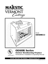
Fig. 19 Attic shield installlation (Canadian requirement).
Model 11CF chimney is not approved
for use in Canada.
IGF263
MBUF
5/9/96
Attic Insula-
tion Shield
Nails
(4 required)
Attic Joist
Ceiling
Base
Flanges
14
STR/CVR Series Woodburning Fireplaces
7412961
WARNING: DO NOT PACK REQUIRED AIR SPACES
WITH INSULATION OR OTHER MATERIALS.
Mark an outline of the roof hole around the center of the
point nail. NOTE: Hole dimensions given in the chim-
ney top installation instructions are horizontal dimen-
sions; therefore, the hole size must be marked on the
roof accordingly.
Cover the opening of the installed chimney so debris
cannot get into the system.
Cut and frame the hole. It is good practice to use fram-
ing lumber that is the same size as the rafters. Install
the frame securely because the chimney top and flash-
ing anchored to the frame must be able to withstand
heavy winds.
Install Remainder of Chimney Sections
Since you have already preplanned the height of your
termination according to the Ten Foot Rule, continue to
install pipe to the predetermined height.
Check the chimney top installation instructions for
details on how high above the roof top the chimney sec-
tions (all pipes) should extend.
Installing Top Housing or Termination
Follow the installation instructions provided with the
chimney termination you have selected.
Installing Chimney In a Chase
Refer to Page 5, Figure 4 for an illustration of a typical
chase installation.
CAUTION: Treatment of firestop spacers and construc-
tion of chase may vary with type of building. These
instructions are not a substitute for local building codes.
You must check your local building codes to determine
specific requirements for your city or state. NOTE:
Other building materials may be required in addition to
Firestop Spacers.
Finishing
CAUTION: All joints between the finished wall and the
fireplace surround (top/sides) must be sealed with non-
combustible material to prevent cold air leakage into the
room. Only noncombustible material may be applied
to the facing of the fireplace surround. (Black painted
area) (Fig. 20)
Finish Wall
Finish the wall with material of your choice. Do not
install a combustible mantel shelf less than 12"
(305mm) above the front opening. Do not install a
mantel face plate less than 6" (159mm) from top of
fireplace opening. (Fig. 21) If a combustible mate-
rial is used below a flat mantel shelf, consult your local
building codes for minimum clearance from top of fire-
place opening to bottom of mantel shelf.
NOTE: No side wall protection is required for fireplaces
installed at 45° to two (2) side walls (corner installation).
Adjacent combustible side walls that are within 16"
(406mm) (STR33/36 and CVR36) and 20" (508mm)
(STR42 and CVR42) of fireplace opening must be pro-
tected with CFM Corporation Wall Shield Model SP40
or a specifically built wall shield described in Figure 20
& 24.
Often a decorative surround or vertical portion of the
mantel is desired. If this is constructed of any combus-
tible material, it must be within the safe zone indicated
in Figure 24.
FP717
Fig. 20 Minimum clearances to combustibles.
Front View
Side View
Standoff
Combustible framing material MUST NOT
penetrate AIR SPACE (shaded areas).
Air Space Clearances
Only noncombustible
material may be applied
as facing to the black
fireplace surround.
Wall
Shield
Hearth
Extension
0" Clearance
to Floor
Firestop
OUTER
DOME
" (13mm)
Air Space
to Sides
" (13mm) air space
to sides
FP717
STR/CVR
AIR SPACES
9/23/98
1" (38mm)


1"
(51mm)


Maintain
" (13mm)
air space
to sides
15
STR/CVR Series Woodburning Fireplaces
7412961
MA81
rev. 8/5/97
1"
Ref.
Combustible materials are
permitted within a shaded area
shown in Figure 23, titled
Minimum Wall Clearances.
*
* *
MA81
Fig. 22 Combustible mantel clearances.
Face Plate
*12" (305mm) from top of fireplace opening.
** 6" (159mm) from top of fireplace opening.
(Noncombustible material must separate the
black face surround of the fireplace and any
combustible mantel material)
FP721
STR/CVR
6/4/98
"
1/2"
*
12"
(305mm)
Min.
12"
(305mm)
Max.
1/2"
12"
(305mm)
Min.
12"
(305mm)
Max.
6'
(159mm)
Min.
FP721
Fig. 21 Fireplace surround flush with finished wall.
Mantel Clearance -
No Noncombustible Facing Material
Finished Wall
Standoff
2 x 4 Stud
Noncombustible Mate-
rial
Header
Ledge Bracket
Fireplace
Front
Fireplace Opening
* Minimum width from top of sur-
round to bottom of screen rail
Combustible
Mantel and Trim
Combustible
Mantel and Trim
Standoff
Finished Wall
2 x 4 Stud
Noncombustible Mate-
rial
Header
Ledge Bracket
Fireplace
Front
Fireplace Opening
Noncombustible Facing Material
Finished Wall
2 x 4 Stud
Must be sealed with
noncombustible material
Fireplace
Front
Mantel Clearance -
with Noncombustible Facing Material
16
STR/CVR Series Woodburning Fireplaces
7412961
Side Wall Protection
All joints (top, bottom and sides) where wall or deco-
rative facing material meets fireplace surround must
be completely sealed with a noncombustible material.
(Figs. 20 and 24)
The special wall shield design described in Figure 20 is
an alternate method of adding protection to side walls
and can be used in place of the SP40 with the same
wall clearances specified for the SP40. Rt must =1.85
minimum.
Examples of wall shield insulation:
1. Manville - CERAFORM 126, K=.27,
1/2 inches thick
2. CFM Corporation - EH2416, K = .458,
1 inch thick required.
FP723
Fig. 23 Minimum firebox dimensions from combustible materials.
FP723
STR/CVR Side Wall clearances
6/21/98
A
A
B
B
C
CC
D
Perpendicular Side Wall
Parallel Side Wall
Perpendicular Side Wall
Parallel Side Wall
STR Series
CVR Series
Minimum Dimensions to Side Walls
(for on-site contruction)
Model STR33 STR36 STR42 CVR36 CVR42
Parallel Side Wall A 44" 44" 44" 44" 44"
to Movable Doors (1118mm) (1118mm) (1118mm) (1118mm) (1118mm)
Perpendicular B 16" 16" 20" 16" 20"
Side Wall to Firebox Opening (406mm) (406mm) (508mm) (406mm) (508mm)
Air Space to Sides C 1/2" 1/2" 1/2" 1/2" 1/2"
or Back of Unit (13mm) (13mm) (13mm) (13mm) (13mm)
End Panel Parallel D -- -- -- 36" 36"
to End of Unit (914mm) (914mm)
17
STR/CVR Series Woodburning Fireplaces
7412961
WARNING: HEARTH EXTENSION MUST BE IN-
STALLED IN ACCORDANCE WITH FIGURES 24 AND
25.
Alternate noncombustible materials may be used
providing the (total) thermal resistance (Rt value) of the
alternate material employed is greater than or equal to
R = 1.09. Thermal resistance (R) or thermal conductivity
(K), may be obtained from manufacturer of the material.
Factors are related by the formula K = 1/R.
T = given thickness
R = thermal resistance for a given thickness (T)
K = thermal conductivity
Noncombustible material with a lower R value may
be used, provided thickness of material is sufficiently
greater to maintain an equivalent (total) thermal resis-
tance (Rt).
Hearth Installation
A hearth extension is required to protect a combustible
floor in front of the fireplace. Refer to Figure 24 for mini-
mum dimensions and mounting detail.
Note: Hearth Extension must not cover the air inlet
opening of a fireplace.
The hearth extension described in Figure 24 must be a
durable noncombustible material with a minimum (total)
Rt value of 1.09; refer to Figure 25 for examples. The
overall height (above a combustible floor), depth and
width must be as indicated, with the extension centered
to the fireplace opening.
The top of the insulation material must be covered with
a noncombustible decorative covering or a piece of
.018” minimum sheet metal, to protect hearth extension
material. (Fig. 24)
Secure the hearth extension to the floor to prevent
shifting, using trim molding or other similar means at
three (3) outer edges. Seal crack between the fireplace
hearth and hearth extension with a noncombustible
material. (Figs. 24 and 26)
Minimum Wall Clearances
WITH
Noncombustible
Surround Facing
WITHOUT
Noncombustible
Surround Facing
Minimum Hearth Extension Dimensions
(for On-Site Construction)
G
H
G
J
Seal cracks
between the
fireplace
and hearth
extension with
noncombustible
material
Safety strips
must overlap
" minimum
May install
noncombustible
decorative
covering
OR .018" min.
sheet metal
Fireplace
Hearth
Combustible
Floor
Minimum
Insulation
Value "R"
4" MIN.
FP714
STR/CVR
6/4/98
Firebox
Opening
A - Min. clearance
to combustible
perpendicular wall
B - Min. clearance
to combustible
perpendicular wall when
using noncombustible wall shield*
Side
Wall
Side
Wall
F**
C**
E
E
D
4" BRICK
(Example material)
Combustible material permitted within shaded area.
*
Noncombustible wall shield requires 1" CFM Corporation
EH2416 insulation (minimum R Value = 1.85) between
decorative noncombustible rigid covering and combustible wall.
Minimum height and width is 40" x 40".
**
Dimension/degree of angle will vary depending on thickness
of noncombustible surround facing.
G
H
G
J
CVR
STR
4"
Shaded area starts
1/2" away from
edge of unit
A B C D E F G H J K
STR33/36 CVR36 16" 12" 48° 41° 18" 14" 8" 16" 48" 24"
(406mm) (305mm) (457mm) (356mm) (203mm) (406mm) (1219mm) (610mm)
STR42 CVR42 20" 12" 42° 35° 18" 14' 12" 20" 61¹⁄₂" 24"
(508mm) (305mm) (457mm) (356mm) (305mm) (508mm) (1562mm) (610mm)
FP714
Fig. 24 Combustible side wall protection and hearth extension dimensions.
18
STR/CVR Series Woodburning Fireplaces
7412961
Example of Determining Hearth Extension
Equivalents
To determine the thickness required for any new mate-
rial:
COMMON MATERIALS AND FACTORS
MATERIAL K*
R
MINIMUM
THICKNESS
EH2416
Common Brick
0.458
5.0
1.09 0.50 in.**
0.10 5.46 in.**

R Value is for  inch.
* Units of K = BTU/SQ FT/HR/˚F/IN
** Thickness of Listed Material
FP533ADD
Addendum
6/1/99 djt
8/4/99 changed .2 to .1
one inch to 1/2 inch djt
FP533AD
Fig. 25 Hearth extension material factors.
FP719
STR/CVR finish wall treatments
5/28/98
Wall Covering
Noncombustible
Decorative
Facing
Noncombustible
Decorative
Covering
Seal all cracks
between fireplace
surround and wall
materials with
noncombustible
material.
Seal crack
between fireplace
and hearth extension
with noncombustible
material.
2x4" Header -
Do not notch at
standoffs.
2x4"
Stud
Safety Strips -
Must be overlapped
" minimum.
Hearth Extension
Insulation
Side View
NOTE: /"
air space
between
Outer Dome
and
combustible
materials
/"
/"
Outer Dome
FP719
Fig. 26 Finish wall treatments and gap sealing.
NEW K of new material (per inch) thickness
required =
X of listed
thickness K of listed material (per inch) material
Example for Common Brick
T (new) = 5.0 / 0.458 x 0.50 in. = 5.46 in. (new required
thickness).



Majestic Safety
Strips Must be
Overlapped 1/2"
Min.
Minimum Insulation
Value R-0.94
1/4" Min. Thickness
Combustible
Floor
Noncombustible
Material 7¹⁄₂"
Max. Thickness
Seal Cracks Between Fireplace and Hearth
Extension with Noncombustible Material
Noncombustible
Material
Lower Surround
Fireplace
Hearth
FP1170
Fig. 27 Hearth extension dimensions.
2”
(51 mm)
2”
(51 mm
)
Maximum
14”
(356 mm)
Maximum
10”
(254 mm)
A
A



Minimum
33”
(838 mm)
Minimum
36” (914 mm)
6”
(152 mm)
Minimum
Minimum .030 Thick Stain-
less Steel Plate
Insulation with Minimum R
Value of 2.75
Minimum .030
Thick Stainless
Steel Plate
View A
NOTE: If noncombustible material is not used between the
stainless steel plate and fireplace opening, the steel must
be attached to the front of the unit a minimum of four (4)
places on each piece with sheet metal screws no longer
than 1/2".
NOTE: The size of the insulation and stainless steel
plate must be within limits stated above and covers all
combustible framing material.
Fig. 28 Recessed installation.
FP1608
Hearth
Extension
Hearth Extension
Noncombustible
Material
(if desired)
Insulation
with Minimum
R Value
of 2.75
Recessed Installation - STR33/36, CVR36 Only
19
STR/CVR Series Woodburning Fireplaces
7412961
Installing Line for Gas Logs
Majestic Fireplaces are designed to accept a 1/2"
(13 mm) gas line for installation of an approved gas ap-
pliance. (CFM Corporation manufactures a wide variety
of gas logs for use in Majestic fireplaces.)
Be sure to have the appliance installed in accordance
with building codes.
Gas connection may enter from either left or right side
of the fireplace.
Locate appropriate gas line in the outer casing of fire-
place and remove insulation from gas line tube. (Fig. 29)
From inside the fireplace, locate the knockout on the
firebrick -- be sure you are on the appropriate or "gas
line" side of the fireplace. Using a flat bladed screw-
driver or small chisel and hammer, carefully tap around
the knockout until it loosens and falls out.
Install 1/2" (13 mm) certified gas pipe through opening.
After gas pipe installation is complete, use insulation
that was removed from gas line tube to repack space
around the pipe. Material should be inserted from
outside of the fireplace and packed tightly to totally seal
between the pipe and tube.
NOTE: Gas pipe should not come in contact with
any wood structures until it has reached a point at
least 1" (25 mm) away from fireplace side.
Note: Local codes may require removal of flue damper
when installing any type of gas appliance in a fireplace.
NOTE: When installing an ANSI Z21.11.2 ventless ap-
pliance, the fninshing material used for the mantel must
be rated at 250°F or greater.
BTU input of a gas appliance installed in fireplace
should be rated less than 100,000 BTU/Hr.
Gas pipe installation is intended for connection to a
decorative gas appliance only when (1.) incorporating
an automatic shutoff device and (2.) complying with the
Standard for Decorative Gas Appliances for Installation
in Vented Fireplaces (ANSI Z21.60) or CSA draft re-
quirements for Gas-Fired Log Lighters for Woodburning
Fireplaces (Draft No. 4, August 1993).
Decorative gas appliance should be installed in accor-
dance with the National Fuel Gas Code, ANSI Z223.1/
NFPA 54 (latest edition).
1"
FP716
CVR/STR Gas Access
5/29/98
FP716
Fig. 29 Gas line access.
Fireplace Top View
Hole in
Outer
Casing
Gas Line
Tube
Supply Line
Repack Insu-
lation
Ceramic
Knockout
(Both Sides
on STR)
Hole in
Outer Cas-
ing
CAUTION: WHEN USING DECORATIVE
GAS APPLIANCE, FLUE DAMPER MUST
BE SET IN FULLY OPEN POSITION. IF YOU
HAVE GLASS DOORS ON THE FIREPLACE,
THEY MUST ALSO BE FULLY OPENED.
WARNING: DO NOT OPERATE AN
UNVENTED GAS LOG SET IN THIS FIRE-
PLACE WITH THE CHIMNEY REMOVED.
WARNING: WHEN INSTALLING AN
UNVENTED GAS LOG SET, THE CFM
CORPORATION MODEL AH3244BK OR
AH3244PB 4" ADJUSTABLE HOOD MUST
BE USED.
Only unvented gas log sets which have been found to comply
with the Standard for Unvented Room Heaters, ANSI Z21.11.2,
are to be installed in this fireplace.
If installing an unvented gas log set, refer to statement below:
20
STR/CVR Series Woodburning Fireplaces
7412961
5a
1, 2, 3
4a
6
7
a
b
c
d
8
9
10
11
961
CVR parts
5/17/00 djt
5b
4b
e
12
13
14
CFM Corporation reserves the right to make changes in design, materials, specifications, prices and discontinue colors and products at any time,
without notice.
961
CVR36/42 SERIES
Ref. Description CVR36 CVR42
1. Flue Damper RP102 RP161
2. Damper Actuator 7548170 7548169
3. Damper Handle Push Nut 7512903 7512903
4a. Screen Rod Assembly - Side (two per fireplace) 3030126 3032112
4b. Screen Rod Assembly - End 7554342 7554342
5a. Screen Assembly - Side (four per fireplace) 7554338 7554340
5b. Screen Assembly - End 7554340 7554340
6. Screen Pulls (four per fireplace) 5584139 5584139
7a. Firebrick - Hearth 3102103 3101105
7b. Firebrick - Side Ash Lip (two per fireplace) 3102102 3101103
7c. Firebrick - End Ash Lip 3101104 3101104
7d. Firebrick - Side 3079147 3079147
7e. Firebrick - Side Filler (two per fireplace) 3079148 3079148
8. Top Brick Retainers (two per fireplace) 3079130 3079130
9. Cable Clips (twelve per fireplace) 7512135 7512135
10. End Panel (Glass and Extrusion) 3080145 3080145
11. Tempered Glass (two per fireplace) 20000399 20000399
12. Nailing Flange (four per fireplace) 5069164 5069164
13. Basket Grate 2056100 2058100
14. O.S.A. Assy. 20003212 20003212
  • Page 1 1
  • Page 2 2
  • Page 3 3
  • Page 4 4
  • Page 5 5
  • Page 6 6
  • Page 7 7
  • Page 8 8
  • Page 9 9
  • Page 10 10
  • Page 11 11
  • Page 12 12
  • Page 13 13
  • Page 14 14
  • Page 15 15
  • Page 16 16
  • Page 17 17
  • Page 18 18
  • Page 19 19
  • Page 20 20
  • Page 21 21
  • Page 22 22
  • Page 23 23
  • Page 24 24
  • Page 25 25
  • Page 26 26
  • Page 27 27
  • Page 28 28

Majestic CVR36 User manual

Category
Fireplaces
Type
User manual

Ask a question and I''ll find the answer in the document

Finding information in a document is now easier with AI