Page is loading ...

1
Majestic Designer Series • DSR42 Installation Manual • 4012-134 • Rev I • 08/20
WOODBURNING FIREPLACE
Fire Risk.
WARNING
For use with solid wood fuel only.
Other fuels may overre and generate
poisonous gases (i.e. carbon monoxide).
Model(s):
Installation Manual
Installation and Fireplace Setup
WARNING
HOT SURFACES!
Glass and other surfaces are hot during
operation AND cool down.
Hot glass will cause burns.
•DO NOT touch glass until it is cooled
• NEVER allow children to touch glass
• Keep children away
• CAREFULLY SUPERVISE children in same room as
replace.
• Alert children and adults to hazards of high temperatures.
High temperatures may ignite clothing or other ammable
materials.
• Keep clothing, furniture, draperies and other ammable
materials away.
INSTALLER: Leave this manual with party responsible for use and operation.
OWNER: Retain this manual for future reference.
DSR42
NOTICE: DO NOT discard this manual!
•DO NOT store or use gasoline or other am-
mable vapors and liquids in the vicinity of this
or any other appliance.
•DO NOT overre. Overring will void your
warranty.
• Comply with all minimum clearances to com-
bustibles as specied. Failure to comply may
cause house re.
WARNING: If the information in these
instructions is not followed exactly, a re
or explosion may result causing property
damage, personal injury, or death.
Installation and service of this appliance should be performed by
This replace uses SL1100 Series Chimney
2” CLEARANCE TO COMBUSTIBLES AND BUILDING INSULATION FROM CHIMNEY REQUIRED.

2Majestic Designer Series • DSR42 Installation Manual • 4012-134 • Rev I • 08/20
Safety Alert Key:
• DANGER! Indicates a hazardous situation which, if not avoided will result in death or serious injury.
• WARNING! Indicates a hazardous situation which, if not avoided could result in death or serious injury.
• CAUTION! Indicates a hazardous situation which, if not avoided, could result in minor or moderate injury.
• NOTICE: Indicates practices which may cause damage to the replace or to property.
Table of Contents
1 Product Specic & Important Safety Information
A. Fireplace Certication 4
B. Non-Combustible Materials 4
C. Combustible Materials 4
2 Getting Started
A. Typical Fireplace System 5
B. Design and Installation Considerations 6
1. Selecting Fireplace Locations 6
2. Locating Fireplace & Chimney 7
C. Tools and Supplies Needed 8
D. Inspect Fireplace and Components 8
E. Fireplace System Requirements 8
3 Framing and Clearances
A. Fireplace Dimensions 9
B. Clearances 10
Minimum Clearances to Combustibles 10
C. Construct the Chase 11
D. Frame the Fireplace 12
E. Secure and Level the Fireplace 12
F. Protective Metal Hearth Strips 13
G. Outside Air Kit 14
4 Chimney and Termination Requirements
A. Chimney Requirements 15
B. Osets/Returns 16
C. Termination Requirements 17
5 Chimney Installation
A. Typical Chimney System 18
B. Assemble Chimney Sections 19
C. Install Chimney Air Kit 19
D. Secure Oset/Return 20
E. Install Ceiling Firestops 20
F. Install Attic Insulation Shield 21
G. Roof Penetration 22
H. Install Chase/Chase Top 22
I. Termination Cap Requirements 23
J. Install Termination Cap 23
6 Shrouds
A. Radiation Shield 25
1. Open Top Shroud 25
2. Mailbox Style Shroud 26
3. Roofed Style Shroud 26
7 Finishing
A. Finishing Material 27
B. Hearth Extension, Building and Finishing 28
1. Fireplace Installed Flush on the Floor
and Hearth Extension Raised to Bottom
of Firebox Opening 29
2. Raised Hearth Extension and Raised Fireplace 30
C. Non-Combustible Sealant Material 31
D. Mantel and Wall Projections 32
E. Sidewalls/Surrounds 33
8 Fireplace Setup
A. Gas Log/Lighter Provision 34
9 Reference Materials
A. Chimney Components 35
B. Optional Components 39
►
►
►
►
►

3
Majestic Designer Series • DSR42 Installation Manual • 4012-134 • Rev I • 08/20
Customer:
Lot/Address
Model (circle one): DSR42
YES IF NO, WHY?
WARNING! Risk of Fire or Explosion! Failure to install fireplace acording to these instructions can lead to a fire or
explosion.
Verified that the chase is insulated and sealed. (Pg. 11)
Verified clearances to combustibles. (Pg. 10)
Fireplace is leveled and secured. (Pg. 12)
Hearth extension size/height decided. (Pg. 28)
Chimney configuration complies with diagrams.
Chimney installed, locked and secured in place with proper clearance.
Chimney air kit installed.
Firestops installed.
ATTENTION INSTALLER:
Follow this Standard Work Checklist
This standard work checklist is to be used by the installer in conjunction with, not instead of, the instructions contained in this installation
manual.
Date Installed:
Location of Fireplace:
Installer:
Dealer/Distributor Phone #
Serial #:
Roof flashing installed.
Termination installed.
Protective hearth strips installed per manual requirements. (Pg. 13)
Fireplace Install
Outside air kit installed. (Pg 14)
Chimney Section 4 & 5 (Pg. 15)
Attic insulation shield installed.
Shrouds Section 6 (Pg. 25)
Shroud is installed properly per instructions.
Fi i hi
S ti 7 (P 27)
Hearth & Home Technologies recommends the following:
Comments communicated to party responsible
4012-136 • Rev B • 03/28/16
All packaging and protective materials removed.
Optional doors properly installed.
Molded brick panels installed correctly.
Grate is properly installed.
Firescreen properly installed.
__________________________ by ______________________on _________
(Builder/Gen. Contractor) (Installer) (Date)
Comments: Further description of the issues, who is responsible (Installer/Builder/Other Trades, etc.) and corrective action needed:
Manual bag and all of its contents are removed from the fireplace and given to the party
responsible for use and operation.
• That this checklist remain visible at all times on the fireplace until the installation is complete.
• Photographing the installation and copying this checklist for your file.
Combustible materials not installed in non-combustible areas.
Finishing Section 7 (Pg. 27)
Hearth extension installed per manual requirements.
Fireplace Setup Section 8 (Pg. 34)
Verified all clearances meet installation manual requirements.
Mantels and wall projections comply with installation manual requirements.

4Majestic Designer Series • DSR42 Installation Manual • 4012-134 • Rev I • 08/20
WARNING! Risk of Fire! Hearth & Home Technologies
disclaims any responsibility for, and the warranty and
agency listing will be voided by the following actions.
DO NOT:
• installoroperatedamagedreplace
• modifyreplace
• install other than as instructed by Hearth & Home
Technologies
• operate the fireplace without fully assembling all
components
• overre
• install any component not approved by Hearth & Home
Technologies
• install parts or components not Listed or approved
Improper installation, adjustment, alteration, service or
maintenance can cause injury or property damage. For
assistance or additional information, consult a qualied
installer, service agency or your dealer.
B. Non-Combustible Materials
• Materials which will not ignite and burn, composed of
any combination of the following:
- Steel - Iron
- Brick - Tile
- Concrete - Slate
- Glass - Plasters
• Materials reported as passing ASTM E 136, Standard
Test Method for Behavior of Metals, in a Vertical Tube
Furnace at 750° C
C. Combustible Materials
• Materials made of or surfaced with any of the following
materials:
- Wood - Compressed paper
- Plant bers - Plastic
- Plywood/OSB - Sheet rock (drywall)
• Any material that can ignite and burn; ame proofed or
not, plastered or un-plastered
1 Product Specic & Important Safety Information
A. Fireplace Certication
WARNING: This product and the fuels
used to operate this product (wood and
wood pellets), and the products of combus-
tion of such fuels, can expose you to chemi-
cals including carbon black, which is known
to the State of California to cause cancer
and carbon monoxide, which is known to
the State of California to cause birth defects
or other reproductive harm. For more infor-
mation go to: www.P65Warnings.ca.gov.
This replace may be installed in sleeping rooms. This
replace is not approved for installation in manufactured
homes. If installed with a gas log set, provisions for the
National Fuel Gas Code must be met.
This replace has been tested and listed for use with the
optional components specied in this manual. These op-
tional components may be purchased separately and in-
stalled at a later date. An outside air kit, gas insert, gas
log set or gas log-lighter should be installed at the time of
replace installation.
This replace system has been tested and listed in accor-
dance with UL 127 and ULC-S610 standards by Underwrit-
ers Laboratories Inc. for installation and operation in the
United States and Canada.

5
Majestic Designer Series • DSR42 Installation Manual • 4012-134 • Rev I • 08/20
2 Getting Started
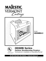
A. Typical Fireplace System
Figure 2.1 Typical Fireplace System
)
)
)
)
)
)
)
)
)
)
)
)
)
)
)
)
)
)
)
)
)
)
)
)
)
)
)
)
)
)
)
))
)
)
)
)
)
)
)
)
)
)
)
)
)
)
)
)
)
)
)
)
)
)
)
)
)
)
)
)
Non-combustible
roof flashing maintains
minimum clearance
around chimney
Additional lateral
support for chimney
above roof (or enclosed
in chase) if needed
Ceiling firestop
on floor of attic
Support straps
on rafter support
chimney (not shown)
Termination cap
Chimney penetrates roof
preferably without affecting
roof rafters
Offset & Return (with hanger straps)
Framing headed off
in ceiling joists
Enclosed space above
and around fireplace
Mantel and surround
Decorative facing
and trim
Hearth extension
Factory-built fireplace
Protective metal
hearth strip(s)
Outside
combustion air
Combustible framing/header
on top of V-shaped standoffs
Chimney system
Attic insulation shield (not shown)
must be used here to keep
insulation away from chimney
if attic is insulated
Storm Collar
Chimney Air Kit
Required in
Canada. Outlet
must be no
less than 4 ft.
(1.322 m) off
ground level.

6Majestic Designer Series • DSR42 Installation Manual • 4012-134 • Rev I • 08/20
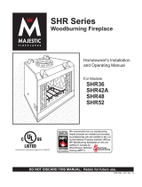
1/2 in. (13 mm)
all configurations
66 in.
(1676 mm)
42 in.
(1067 mm)
20 in. (508 mm)
(hearth
extension)
64 in.
(1626 mm)
12 in. (305 mm)
min. to
perpendicular
wall.
Figure 2.2 Fireplace Locations
NOTICE:
• Illustrationsandphotosreecttypicalinstallationsand
are FOR DESIGN PURPOSES ONLY.
• Illustrations/diagrams are not drawn to scale.
• Actual installation/appearance may vary due to individual
design preference.
• Hearth & Home Technologies reserves the right to alter
its products.
NOTICE: In addition to these framing dimensions, also
reference the following section:
• Clearances (Section 3).
NOTICE:
A minimum 1/2 in. air clearance at the back and
sidesofthereplaceassemblymustbemain-
tained.
Chimney sections at any level require a 2 in. mini-
mum air space clearance between the framing
and chimney sections.
B. Design and Installation Considerations
NOTICE: Check building codes prior to installation.
• Installation MUST comply with local, regional, state and
national codes and regulations.
• Consult insurance carrier, local building inspector, re
ocials or authorities having jurisdiction over restrictions,
installation inspection and permits.
• Before installing, determine the following:
- Where the replace is to be installed.
- The vent system conguration to be used.
- Gas supply piping.
- Electrical wiring.
- Framing and nishing details.
- Whether optional accessories - devices such as a
fan, wall switch or remote control - are desired.
1. Selecting Fireplace Locations
This replace may be used as a room divider. See Figure
2.2.
Locating the replace in a basement should be avoided.
Locating near frequently opened doors, central heat
outlets or returns, or other locations of considerable air
movement can aect the performance.
Outside air is recommended for combustion. This replace
comes equipped with an outside air inlet to feed combus-
tion air from outside the home, along with an outside air
termination cap; the duct is required but not supplied. Con-
sideration should be given to these factors before deciding
on a location.

7
Majestic Designer Series • DSR42 Installation Manual • 4012-134 • Rev I • 08/20
2. Locating Fireplace & Chimney
Location of the replace and chimney will aect perfor-
mance.
• Install within the warm airspace enclosed by the building
envelope. This helps to produce more draft, especially
during lighting and die-down of the re.
• Installing the replace in a basement is not recommended.
• Penetrate the highest part of the roof. This minimizes
the eects of wind loading.
• Locate termination cap away from trees, adjacent
structures, uneven roof lines and other obstructions.
• Minimize the use of chimney osets.
• Consider the replace location relative to oor and ceiling
and attic joists.
• Take into consideration the termination requirements in
Sections 4 and 5.
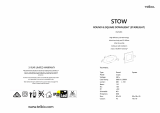
Marginal Location:
• Below peak
Location NOT recommended:
• Not the highest point of the roof
• Wind loading possible
Multi-level Roofs
Windward
Leeward
Recommended Location:
• Above peak
Recommended:
• Insulated exterior chase
in cooler climates
Recommended Location:
• Above peak
• Inside heated space
Location NOT recommended:
• Too close to tree
• Below adjacent structure
• Lower roof line
• Avoid outside wall
Marginal Location:
• Wind loading possible
Not recommended in basement due
to high negative pressure concerns
that effect draft
Figure 2.3 Recommended Chimney Locations
• Install the outside air kit with the intake facing prevailing
winds during the heating season.
• Ensure adequate outdoor air for all combustion
appliances and exhaust equipment.
• Ensure furnace and air conditioning return vents are not
located in the immediate vicinity of the replace.
• Avoid installing the replace near doors, walkways or
small isolated spaces.
• Recessed lighting should be a “sealed can” design.
• Attic hatches weather stripped or sealed.
• Attic mounted duct work and air handler joints and seams
taped or sealed.

8Majestic Designer Series • DSR42 Installation Manual • 4012-134 • Rev I • 08/20
C. Tools and Supplies Needed
Before beginning the installation be sure the following
tools and building supplies are available:
Reciprocating saw Framing material
Pliers Non-combustible sealant
Hammer Gloves
Phillips screwdriver Framing square
Flat blade screwdriver Electric drill and bits
Plumb line Safety glasses
Level Tape measure
1/2-3/4 in. length, #6 or #8 self-drilling screws
Misc. screws and nails
D. Inspect Fireplace and Components
WARNING! Risk of Fire and/or Explosion! Damaged
parts could impair safe operation. DO NOT install dam-
aged,incompleteorsubstitutecomponents.Keepre-
place dry.
• Remove replace and components from packaging and
inspect for damage.
• Vent system components and doors are shipped in
separate packages.
• Report to your dealer any parts damaged in shipment.
• Read all the instructions before starting the
installation. Follow these instructions carefully
during the installation to ensure maximum safety
and benet.
E. Fireplace System Requirements
The HHT replace system requirements consist of the
following:
• Fireplace
- Refractory (included with replace)
- Firescreen (included with replace)
- Grate (included with replace)
- Hearth Extension (required, sold separately)
• Outside Air System
- Air Inlet Hood (included with replace)
- Flex (required, sold separately)
• Chimney System
- Attic Insulation Shield (included with replace)
- Chimney air kit (required in Canada, sold separately)
- Chimney termination cap (required, sold separately)
• Non-combustible nish material

9
Majestic Designer Series • DSR42 Installation Manual • 4012-134 • Rev I • 08/20
3 Framing and Clearances
A. Fireplace Dimensions
Gas
Knockout
Outside
Air
58-7/8 in.
(1496 mm)
(effective height)
38-3/8 in.
(975 mm)
11-3/4 in.
(298 mm)
8-5/8 in.
(219 mm)
13 in.
[330 mm]
dia.
42 in.
(1067 mm)
23 in.
(585 mm)
7-1/2 in.
(192 mm)
39-1/8 in.
(995 mm)
Gas
Knockout
8-3/8 in.
(213 mm)
14 in.
(356 mm)
8-3/8 in.
(213 mm)
14 in.
(356 mm)
47 in.
(1194 mm)
28 in.
(711 mm)
23-1/2 in.
(597 mm)
14 in.
(356 mm)
5-7/8 in.
(149 mm)
Figure 3.1 Fireplace Dimensions

10 Majestic Designer Series • DSR42 Installation Manual • 4012-134 • Rev I • 08/20
B. Clearances
WARNING! Risk of Fire!
You must comply with all minimum air space clearances
tocombustiblesasspeciedinFigure3.2.DO NOT pack
required air spaces with insulation or other materials.
Framing or nishing material used on the front of, or in
frontof,thereplacecloserthantheminimumslistedmust
be constructed entirely of non-combustible materials (i.e.,
steel studs, concrete board, etc.). Failure to comply may
causere.
Minimum Clearances to Combustibles
WITHIN ENCLOSURE AREA
Fireplace to sidewall 1/2 in. (13 mm)
Top standos to header 0 in. (0 mm)
Door opening to sidewall 12 in. (305 mm)
MANTEL
Mantel minimum height 12 in. (305 mm)
above opening
Maximum mantel depth 12 in. (305 mm)
Figure 3.2 Clearances to Combustible Materials
(roof)
(insulation)
0 in. to level
of standoffs
Attic
Insulation
Shield
(ceiling)
(attic)
(ceiling)
Offset/Return (secured
with hanger straps)
Storm Collar
Roof Flashing
1/2 in. (13 mm) to
sides of appliance
Must have 2 in. (51 mm)
minimum clearance
to header
0 in.
to floor
2 in. (51 mm) min.
Shaded areas
represent
2 in. (51 mm) min.
air space clearance
required around pipe
Combustible Object
Adapter
Ceiling Firestop
48 in.
1219 mm
Note: Chimney air kit and 11-10
in./279-254 mm adapter are
not shown, but are required in
Canada.

11
Majestic Designer Series • DSR42 Installation Manual • 4012-134 • Rev I • 08/20
C. Construct the Chase
A chase is a vertical boxlike structure built to enclose the
replace and/or its vent system. Vertical chimneys that
run on the outside of a building must be installed inside a
chase.
In cold climates, Hearth & Home Technologies recom-
mends that the chase be well insulated using batt type
insulation between the joists.
Construction of the chase may vary with the type of build-
ing. These instructions are not substitutes for the require-
ments of local building codes. Local building codes MUST
be checked.
Chases should be constructed in the manner of all outside
walls of the home to prevent cold air drafting problems.
The chase should not break the outside building envelope
in any manner. All outer walls need to be insulated.
Building codes require false ceiling and ceiling restops/
attic shields at each oor of the chase or every 10 ft (3048
mm) of clear space to control spread of re.
Walls, ceiling, base plate and cantilever oor at the rst
level of the chase should be insulated (see Figure 3.3.)
Vapor and air inltration barriers should be installed in the
chase as per regional codes for the rest of the home. Ad-
ditionally, Hearth & Home Technologies recommends that
the inside surfaces be drywalled and taped (or the use of
an equivalent method) for maximum air tightness.
Holes and other openings should be caulked with high
temperature caulk or stued with unfaced berglass insu-
lation.
Ceiling
Firestop
Metal Chase Top
Round Termination Cap
False Ceiling
Insulation in the
outside walls
of the chase
Attic
Insulation
Shield
Chimney
Ceiling
Firestop
Tabs
False Ceiling
False Ceiling
Insulation
Insulation
Figure 3.3 Chase Assembly
12
1. Chimney offset through exterior wall and
enclosed in chase.
2. Chase constructed on roof.
Figure 3.4 Chase Constructions
• The chase is constructed using framing materials much
the same as the walls in your home. A variety of siding
materials may be used including brick, stone, veneer
brick, or standard siding materials.
• In constructing the chase, several factors must be
considered:
- Maintain a 2 in. (51 mm) air space around the
chimney.
- The chase top must be constructed of non-
combustible material.
- In cold climates, a restop spacer and attic insulation
shield should be installed in an insulated false ceiling
at the 8 ft. (2438 mm) level above the replace
assembly. This reduces heat loss through the chase.
- In cold climates, the walls of the chase should be
insulated to the level of the false ceiling as shown in
Figure 3.3. This will help reduce heat loss from the
home around the replace.
Examples of chase applications are shown in Figure 3.4.
WARNING! You must install false ceilings and ceil-
ing restops at each oor of the chase or every 10 ft
(3.05 m) to control spread of re.
WARNING! Risk of Fire! DO NOT sealareabetweenre
stop opening and chimney pipe except where they enter
the attic or leave the warm air envelope of the home (use
600° F sealant).
WARNING! Risk of Fire! You must maintain a min-
imum 2 in. (51 mm) air space clearance to insula-
tion and other materials surrounding the chimney
system.
• Insulationandothermaterialsmustbermlysecuredto
prevent accidental contact with chimney system.
• The chase must be properly blocked to prevent blown
insulation or other combustibles from entering and
makingcontactwithreplaceorchimney.
• Failure to prevent contact between insulation or other
materials and chimney system may cause overheating
andre.

12 Majestic Designer Series • DSR42 Installation Manual • 4012-134 • Rev I • 08/20
D. Frame the Fireplace
NOTICE: Hearth extension design must be determined
before installation of replace.
If the replace is placed on the oor the maximum height
of a nished raised hearth is 7 1/2 in. (192 mm), if you want
a higher raised hearth the replace must be placed on a
platform.
WARNING! Risk of Fire! You must comply with all mini-
mum air space clearances to combustibles. DO NOT pack
required air spaces with insulation or other materials.
WARNING! Risk of Fire! Comply with all minimum clear-
ancesspecied.
• A minimum 1/2 in. (13 mm) air clearance must be
maintainedatthesidesofthereplaceassembly.
•Chimney sections at any level require a 2 in. (51
mm) minimum air space clearance between the
framing and chimney section.
Figure 3.5 shows a typical framing (using 2 x 4 lumber) of
the replace, assuming combustible materials are used.
All required clearances to combustibles around the re-
place must be adhered to. See Figure 3.2. Any framing
across the top of the replace must be above the level of
the top standos.
CAUTION! Risk of Cuts/Abrasions. Wear protective gloves
and safety glasses during installation. Sheet metal edges
are sharp.
WARNING! Risk of Fire! Prevent contact with sagging,
loose insulation.
•DO NOT install against vapor barriers or exposed
insulation.
• Secure insulation and vapor barriers.
• Provide minimum air space clearances at the sides and
backofthereplaceassembly.
E. Secure and Level the Fireplace
This replace may be placed on either a combustible or
noncombustible continuous at surface. Follow the instruc-
tions for framing in Section 3. Slide the replace into posi-
tion. Be sure to provide the minimum 1/2 in. air clearance
at the sides of the replace.
The replace should be positioned so the face of the non-
combustible material on the replace will be ush with the
face of the drywall on the walls.
Level the replace and shim as necessary.
17 in. (368 mm)
framing
27 in.
(686 mm)
Note: Fireplace
header cannot be
positioned until after
the fireplace assembly
is in place and set on
edge. The 2 x 4s above
the header will lay flat.
12 in. (305 mm) max.
48 in.
(1219 mm)
3-1/2 in.
(89 mm)
3-1/2 in.
(89 mm)
Figure 3.5 Framing the Fireplace
1/2 in.
(13 mm)
Fireplace must be set out
1/2 in. (13 mm) in front of
the face of the framing
material.
Note: If a load bearing header is required, construct a
standard 2 x 4 header and install at 60 inches up from the
base of the replace. This may be done prior to setting
the replace as it will slide in below the header. After the
replace has been set into the framing cavity, ll in below
the header as shown in Figure 3.5.
NOTE: Before framing up the chase, consider where and
how the chimney will run. If there are obstacles that might
be in the way, it may be necessary to make the
chase larger than shown to allow for offsets to be used.
Refer to offset chart on page 16 if needed.
►

13
Majestic Designer Series • DSR42 Installation Manual • 4012-134 • Rev I • 08/20
Protective metal strips are placed 2 in. (51 mm) under the
front of the fireplace and must extend beyond the front
and sides of fireplace opening by 2 in. (51 mm).
1 in. (25 mm)
overlap
Raised Platform
Floor
2 in.
(51 mm)
1 in. (25 mm) min.
overlap
2 in.
(51 mm)
Top piece must overlap
bottom piece
Figure 3.7 Protect the Front of an Elevated Platform
F. Protective Metal Hearth Strips
Figure 3.6 Position the Protective Metal Hearth Strips
• Locate the four protective metal hearth strips measuring
approximately 26 in. x 4 in. (660 mm x 102 mm) included
with this replace.
• Slide each metal strip 2 in. (51 mm) under front edge of
replace.
• Overlap strips in the middle of replace opening by 1 in.
(25 mm) minimum.
• Metal strips must extend beyond the front and sides
of the replace opening by at least 2 in. (51 mm),
Figure 3.6).
• Protect the front of a platform elevated above the hearth
extension with metal strips (not included with replace)
per Figure 3.6. See Section 7 for hearth extension
instructions.
WARNING! Risk of Fire! Protective metal hearth
strips MUST be installed on combustible surfaces. DO
NOT cover metal strips with combustible materials.
Sparksorembersmayigniteooring.
WARNING! Risk of re! High temperatures, sparks,
embers or other burning material falling from the
replacemayigniteooringorconcealedcombustible
surfaces.
• Protective metal hearth strips MUST be installed.
• Hearth extensions MUST be installed exactly as
specied.

14 Majestic Designer Series • DSR42 Installation Manual • 4012-134 • Rev I • 08/20
G. Outside Air Kit
When you install the outside air kit, Hearth & Home Tech-
nologies recommends you utilize the shortest duct run to
optimize the performance of the outside air kit and install a
P-trap (see Figure 3.10). The outside air inlet hood should
be positioned in a manner that will not allow snow, leaves,
etc. to block the inlet. In some installations the air duct
may need to be run vertically. In such an installation, a 3
ft (914 mm) height dierence must be maintained from the
top of the uppermost chimney section to the outside air
inlet hood.
NOTE: The maximum length of a 4 inch diameter duct is
20 feet. The duct can be extended up to a maximum of 40
feet by using 6 inch duct. A 4 inch to 6 inch adapter will be
needed. (not included).
NOTE: The minimum cross-sectional area of the 4 inch
inlet hood is 7.0 square inches.
Refer to Figures 3.8 and 3.9 when placing the outside air
inlet hood.
Installation
• Remove the cover plate from the side of the replace and
replace it with outside air plate assembly using existing
screws.
• Mark and cut out a 4 1/2 in. (114 mm) diameter hole in
the building side for air entry. This hole should allow for
some framing (two sides) so the outside air inlet hood
may be nailed into position, ush with building’s outside.
• Secure exible duct (not supplied) to the plate assembly.
• Feed duct through hole to the outside, fasten to the
outside air inlet hood.
• Fasten outside air inlet hood assembly to the structure
with screws.
• Seal between the wall and the pipe with silicone to
prevent moisture penetration and air leaks.
• Seal between the outside air inlet hood and the house
with silicone to prevent air inltration.
CAUTION! Risk of Cuts/Abrasions. Wear protective
gloves and safety glasses during installation. Sheet metal
edges are sharp.
CAUTION! Risk of Fire or Asphyxiation! DO NOT draw
outsidecombustionairfromwall,oororceilingcavity,or
enclosed spaces such as an attic or garage.
• DO NOT place outside air inlet hood close to exhaust
vents or chimneys. Fumes or odor could be drawn into
theroomthroughthereplace.
• Locate outside air inlet hood to prevent blockage from
leaves, snow/ice, or other debris. Blockages could cause
combustion air starvation.
)
)
)
)
)
)
)
)
)
)
)
)
)
)
)
)
)
)
)
)
)
)
)
)
)
)
)
)
)
)
)
)
)
)
)
)
)
)
)
)))
)
))
)
)
)
))))
)
))
))
)))
)
)
))
))
))
)
))
)
))
)))
))
)
)
)
)
))
)
)
)
)
)
)
)
)
)
)
)
)
3 ft min. from
top of uppermost
chimney section
to air inlet.
Figure 3.9 Outside Air Inlet Locations
Outlet placed
higher than 3 ft
below the
termination cap
Attic space
Garage or
combustible
liquids storage
Outlet blocked by
snow, leaves, etc.
Clear area
outside
house or in
ventilated
crawl space
YES
NO
NO
NO
NO
Factory-built
fireplace
• Use UL181 Class 1 or Class 0 rigid or flexible ducting.
• Install with short run and add a P-trap which will help
prevent flow of cold air.
• Secure flex duct with screws or wire ties.
Figure 3.8 Outside Air Installation Figure 3.10 Outside Air Installation with Cold Air Trap
Typical Outside Air
Installation
Typical CAK Installation
Seal
Seal
24” (610 mm) min.
48” (1220 mm) max.
Note: The pipe
cannot lay on top
of the unit.
4” Duct-Use UL181
Class 0 or Class 1
ducting
Recommend
around 24 inches
for a minimum bend
Note: Chimney air kit and
11-10 in./279-254 mm
adapter are not shown,
but are required in Canada.
►
►
►

15
Majestic Designer Series • DSR42 Installation Manual • 4012-134 • Rev I • 08/20
d & g
Ceiling Firestop h
i
58-7/8 in.
(1495 mm)
Effective
Height
a,b,c,f
11-10 in. (279-254 mm)
adapter required in
Canada.
Figure 4.1 Chimney Requirements
NOTICE: Amaximumoftwopairsofosetsandreturns
may be used.
WARNING! Risk of Fire! You must maintain 2 in.
(51 mm) air space clearance to insulation and
other combustible materials around the chimney
system. Failure to do so may cause overheating
and re.
NOTICE: You must provide support for the pipe during
construction and check to be sure inadvertent loading has
notdislodgedthechimneysectionfromthereplaceorat
any chimney joint.
A. Chimney Requirements
Vertical distances are measured from the base of the
replace as shown in Figure 4.1.
4 Chimney and Termination Requirements
Table 4.2 Chimney Component Dimensions
Table 4.1 Chimney Requirements ft meters
a. Minimum overall straight height 14.0 4.27
b. Minimum height with oset/return 16.5 5.03
c. Maximum height 90.0 27.43
d. Maximum chimney length between an oset and
return
20.0 6.1
e. Maximum distance between chimney stabilizers 35.0 10.67
f. Double oset/return minimum height 22.0 6.71
g. Maximum unsupported chimney length between the
oset and return
6.0 1.83
h. Maximum unsupported chimney height above the
replace
35.0 10.67
i. Maximum unsupported chimney above roof 6.0 1.83
HEIGHT OF CHIMNEY COMPONENTS in. mm
US Canada ONLY
Chimney Stabilizer
SL11 SL4 4-3/4 121
Osets/Returns
SL1130 SL430 14-1/2 368
Chimney Sections*
SL1106 SL406 4-3/4 121
SL1112 SL412 10-3/4 273
SL1118 SL418 16-3/4 425
SL1136 SL436 34-3/4 883
SL1148 SL448 46-3/4 1187
n/a SLA10 16-3/4 425
* Dimensions reect eective height.

16 Majestic Designer Series • DSR42 Installation Manual • 4012-134 • Rev I • 08/20
B. Osets/Returns
• Use an oset/return to bypass overhead obstructions.
• An oset and return can be used as a single entity or separated by chimney section(s).
WARNING! Risk of Fire! DO NOT useoset/returnsgreaterthan30°.Chimneydraftwillberestrictedandcouldcause
overheatingandre.Secureosetswithscrews(nottoexceed1/2”/13mminlength)Securereturnswithstrapping.
Straight chimney sections may be secured with screws. Keep chimney sections from separating or twisting.
• Measure the shift needed to avoid the overhead obstruction. Refer to dimension A in Figure 4.2.
• Find the appropriate A dimension listed in Table 4.3. The B dimension coinciding with the A dimension measurement in
Table 4.3 represents the required vertical clearance needed to complete the oset/return.
• Read across the chart to nd the number of chimney sections/model numbers needed between the oset and return.
A
B
1-1/4 in. (32 mm)
OVERLAP
Figure 4.2 Chimney Oset/Return
Table 4.3 Oset Dimensions
Example:
Your “A” dimension from Figure 4.2 is 14 1/2 in.
(368 mm). Using Table 4.3 the dimension closest to, but
not less than 14 1/2 in. (368 mm) is 15 3/4 in. (400 mm)
using a 30° oset/return.
You determined from the table that you would need 36-
5/8 in. (930 mm) (Dimension “B”) between the oset and
return.
The chimney component that best ts your application is
two SL1112s.
Note: SL400 series pipe available
for Canada ONLY.
A B SL1106
SL406
SL1112
SL412
SL1118
SL418
SL1136
SL436
SL1148
SL448in. mm in. mm
4 7/8 124 17 7/8 454 -----
7 1/4 184 22 559 1 - - - -
9 3/4 248 26 1/8 664 2 - - - -
10 1/4 260 27 1/4 692 - 1 - - -
12 3/4 324 31 3/8 797 1 1 - - -
13 1/4 337 32 3/8 822 - - 1 - -
15 3/4 400 36 5/8 930 - 2 - - -
18 1/8 460 40 3/4 1035 1 2 - - -
18 3/4 476 41 3/4 1060 - 1 1 - -
21 3/4 552 47 1194 - - 2 - -
22 1/4 565 48 1219 - - - 1 -
24 3/4 629 52 1/8 1324 1 - - 1 -
27 3/4 705 57 3/8 1457 -1-1-
28 1/4 718 58 3/8 1483 ----1
30 3/4 781 62 1/2 1588 1 - - - 1
33 3/4 857 67 3/4 1721 - 1 - - 1
36 3/4 933 73 1854 - - 1 - 1
39 3/4 1010 78 1/8 1984 - - - 2 -
41 1/8 1045 82 3/8 2092 1 - - 2 -
45 3/4 1162 88 1/2 2248 - - - 1 1
48 1/8 1222 92 3/4 2356 1 - - 1 1
51 3/4 1314 98 7/8 2511 ----2
Proper assembly of air cooled chimney parts results in an overlap of chimney joints
of 1-1/4 in. (32 mm). Eective length is built into this table.

17
Majestic Designer Series • DSR42 Installation Manual • 4012-134 • Rev I • 08/20
Slanted Roofs
Flat Roofs
Chimney must
extend 3 ft (.9 m)
above the roof
Chimney must extend 2 ft (.6 m)
above any portion of the roof or
adjacent structures within
10 ft (3 m) of the chimney
Chimney must
extend 3 ft (.9 m)
above the roof
Chimney must extend 2 ft (.6 m)
above any portion of the roof or
adjacent structures within
10 ft (3 m) of the chimney
Multiple Chimney Locations
A B
6 in. (minimum) up to 20 in.
152 mm/508 mm
18 in. minimum
457 mm
20 in. and over 0 in. minimum
Gas, Wood or Fuel Oil
Termination Cap
Wood
Minimum
(See
illustration
above)
B
Gas
Termination
Cap **
A *
Perpendicular Wall
*
If using decorative cap cover(s), this distance may need to be
increased. Refer to the installation instructions supplied with the
decorative cap cover.
**
In a staggered installation with both gas and wood terminations, the
wood termination cap must be higher than the gas termination cap.
Figure 4.3 Multiple Chimney Locations
C. Termination Requirements
• Install a cap approved and listed for this replace system.
• Locate cap where it will not become plugged by snow or other materials.
• Locate cap away from trees or other structures.
• The bottom of the termination cap must be at least 3 ft (.91 m) above the roof AND at least 2 ft (.61 m) above any portion
of roof within 10 ft (3.05 m).
• The distance required between caps is shown below.

18 Majestic Designer Series • DSR42 Installation Manual • 4012-134 • Rev I • 08/20
5 Chimney Installation
Chimney must extend
beyond combustible
roof structure
Maintain minimum
height of chimney
above roof
Additional
support for
tall chimneys
Install roof flashing
according to minimum
requirements
Maintain minimum
clearances to
combustibles as
specified
Offsets/returns
may not exceed
30° from vertical
Lock chimney
sections together
firmly to resist
movement
Ceiling firestops
are required where
chimney passes
through ceiling or
floor
Support straps for offsets
(not shown) must be
secured to adequate framing
Termination Cap
Storm Collar
Offsets/returns must be
secured with screws
(outer pipe only)
Attic shield
The chimney must be
enclosed from the
replace to the attic
maintaining the 2
inch clearances.
Figure 5.1 Typical Chimney System - Guidelines for Chimney System Installation
NOTICE: Chimney performance may vary.
• Trees,buildings,rooflinesandwindconditionsaectperformance.
• Chimney height may need adjustment if smoking or overdraft occurs.
A. Typical Chimney System
►

19
Majestic Designer Series • DSR42 Installation Manual • 4012-134 • Rev I • 08/20
C. Install Chimney Air Kit
• Required in Canada.
• Follow instructions included with accessory.
NOTICE: Chimney sections cannot be disassembled once
locked together. Plan ahead!
• Lock chimney sections and/or osets/returns together by
pushing downward until the top section meets the stop
bead on the lower section.
• Pull on the top section to make sure it is fully engaged
and will not separate.
• You may use #6 or #8 sheet metal screws no longer than
1/2 in. (13 mm) to fasten chimney sections together. Do
NOT penetrate inner ue.
• Fasten oset/returns to chimney sections. Do NOT
penetrate inner ue.
• Secure chimney returns with hanger straps provided;
fasten to studs or joists.
• Vertical straight runs of chimney must be supported every
35 ft (10.7 m).
B. Assemble Chimney Sections
Use only those components described in this manual.
Substitute or damaged chimney components could impair
safe operation and cause overheating and re.
Attach either a straight chimney section or an oset to the
top of the replace (depending on your installation require-
ment). Chimney sections are locked together by pushing
downward until the top section meets the stop bead on the
lower section.
The inner ue is placed to the inside of the ue section be-
low it. The outer casing is placed outside the outer casing
of the chimney section below it. See Figure 5.2.
WARNING! Risk of Fire! DO NOT install substitute or
damaged chimney components.
Figure 5.2 Assembling Chimney Sections

20 Majestic Designer Series • DSR42 Installation Manual • 4012-134 • Rev I • 08/20
D. Secure Oset/Return
E. Install Ceiling Firestops
CAUTION! Risk of Fire! Ceilingrestopsmustbeused
wheneverthechimneypenetratesaceiling/oor.
• Chaseconstructionrequiresceilingrestopsateach
oororevery10ft.(3.05m)ofclearspace.
• Theceilingrestopslowsspreadofreandreduces
coldairinltration.
• Install a ceiling restop whenever chimney penetrates
ceiling/oor.
• Mark and cut an opening in ceiling as shown in Figure 5.4.
• Frame the opening with the same size lumber used in
the ceiling joists.
• Nail the ceiling restop to the bottom of the ceiling joists
when there is a room above.
• Use an attic insulation shield if the ceiling is insulated.
The ceiling restop may then be attached above or below
the joists.
ROOM ABOVE (non-insulated ceiling)
ATTIC ABOVE (insulated ceiling)
B
A
Ceilng firestop
attached to bottom
of framing
Ceiling firestop
attached to top of
framing
Note: Use same dimensional lumber for framing
ceiling firestop and joists.
2 in. (51mm)
clearance
2 in. (51mm)
clearance
WARNING! Risk of Fire! DO NOT seal area between
restopopeningandchimneypipeexceptwheretheyen-
ter the attic or leave the warm air envelope of the home
(use 600° F sealant).
Figure 5.4 Installing the Ceiling Firestop
When osets and returns are joined to straight pipe sec-
tions, they must be locked into position with screws (outer
only). To prevent gravity from pulling the chimney sec-
tions apart, the returns and the chimney stabilizers have
hanger straps for securing these parts to joists or rafters.
See Figure 5.3.
* Use # 6 or # 8 sheet metal screw, or larger, no longer
than 1/2 in. (13 mm).
WARNING! Risk of Fire!
• Secureosetswithscrews(nottoexceed1/2in./13mm
In length).
• Secure returns with strapping.
• Straight chimney sections may be secured with screw
(not to exceed 1/2 in./13 mm In length) at the joints.
• Keep chimney sections from separating or twisting.
Ceiling
Firestop
Straps
Optional
Additional
Support
Joint
Band
(Optional)
Figure 5.3 Secure the Chimney
Catalog #
A B
in. mm in. mm
FS538 17 432 17 432
FS540 17 432 26 660
/