H3C S3100V2 Series Installation guide

Category
Network switches
Type
Installation guide
H3C S3100V2 Switch Series
Installation Guide
Hangzhou H3C Technologies Co., Ltd.
http://www.h3c.com
Document version: 6W103-20110808
Copyright © 2011, Hangzhou H3C Technologies Co., Ltd. and its licensors
All rights reserved
No part of this manual may be reproduced or transmitted in any form or by any means without prior
written consent of Hangzhou H3C Technologies Co., Ltd.
Trademarks
H3C,
, Aolynk, , H
3
Care,
, TOP G, , IRF, NetPilot, Neocean, NeoVTL,
SecPro, SecPoint, SecEngine, SecPath, Comware, Secware, Storware, NQA, VVG, V
2
G, V
n
G, PSPT,
XGbus, N-Bus, TiGem, InnoVision and HUASAN are trademarks of Hangzhou H3C Technologies Co.,
Ltd.
All other trademarks that may be mentioned in this manual are the property of their respective owners
Notice
The information in this document is subject to change without notice. Every effort has been made in the
preparation of this document to ensure accuracy of the contents, but all statements, information, and
recommendations in this document do not constitute the warranty of any kind, express or implied.
Environmental protection
This product has been designed to comply with the environmental protection requirements. The storage,
use, and disposal of this product must meet the applicable national laws and regulations.
Preface
The H3C S3100V2 Switch Series Installation Guide guides you through the installation of your switch.
It covers product overview, preparing for installation, installing the switch, logging in to the switch,
connecting the switch to the network, and troubleshooting.
This preface includes:
Audience
Conventions
Obtaining documentation
Technical support
Documentation feedback
Audience
This documentation is intended for:
Network planners
Field technical support and servicing engineers
Network administrators working with the S3100V2 switch series
Conventions
This section describes the conventions used in this documentation set.
GUI conventions
Convention Description
Boldface
Window names, button names, field names, and menu items are in Boldface. For
example, the New User window appears; click OK.
> Multi-level menus are separated by angle brackets. For example, File > Create > Folder.
Convention Description
< > Button names are inside angle brackets. For example, click <OK>.
[ ]
Window names, menu items, data table and field names are inside square brackets. For
example, pop up the [New User] window.
/ Multi-level menus are separated by forward slashes. For example, [File/Create/Folder].
Symbols
Convention Description
WARNING
An alert that calls attention to important information that if not understood or followed can
result in personal injury.
CAUTION
An alert that calls attention to important information that if not understood or followed can
result in data loss, data corruption, or damage to hardware or software.
IMPORTANT
An alert that calls attention to essential information.
NOTE
An alert that contains additional or supplementary information.
TIP
An alert that provides helpful information.
Network topology icons
Represents a generic network device, such as a router, switch, or firewall.
Represents a routing-capable device, such as a router or Layer 3 switch.
Represents a generic switch, such as a Layer 2 or Layer 3 switch, or a router that supports
Layer 2 forwarding and other Layer 2 features.
Obtaining documentation
You can access the most up-to-date H3C product documentation on the World Wide Web at
http://www.h3c.com
.
Click the links on the top navigation bar to obtain different categories of product documentation:
[Technical Support & Documents > Tech
nical Documents] – Provides hardware installation, software
upgrading, and software feature configuration and maintenance documentation.
[Products & Solutions]
Provides information about products and technologies, as well as solutions.
[Technical Support & Documents > Software Download]
– Provides the documentation released with the
software version.
Technical support
customer_service@h3c.com
http://www.h3c.com
Documentation feedback
You can e-mail your comments about product documentation to [email protected].
We appreciate your comments.
i
Contents
Product overview·························································································································································· 1
Switch models····································································································································································1
Panel views ········································································································································································1
S3100V2-26TP-SI/S3100V2-26TP-EI ····················································································································1
S3100V2-16TP-SI/S3100V2-16TP-EI ····················································································································2
S3100V2-8TP-SI/S3100V2-8TP-EI ·························································································································3
S3100V2-26TP-PWR-EI············································································································································4
S3100V2-16TP-PWR-EI············································································································································5
S3100V2-8TP-PWR-EI ··············································································································································6
Preparing for installation ············································································································································· 8
Safety recommendations ··················································································································································8
General safety recommendations···························································································································8
Safety with electricity ···············································································································································8
ESD prevention ·························································································································································8
Safety with laser ·······················································································································································9
Examining the installation site ·········································································································································9
Temperature requirements ·······································································································································9
Humidity requirements ·············································································································································9
Cleanness requirements········································································································································ 10
EMI requirements··················································································································································· 10
Grounding requirements······································································································································· 11
Cooling requirements············································································································································ 11
Space requirements··············································································································································· 11
Installation tools······························································································································································ 12
Installing the switch····················································································································································13
Installation flow of the switch········································································································································ 13
Installing the switch ························································································································································ 13
Selecting an installation method·························································································································· 13
Installation accessories ········································································································································· 14
Installing the switch into the 19-inch rack··········································································································· 18
Mounting the switch on a workbench················································································································· 24
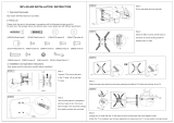
Mounting the switch on a wall····························································································································· 25
Magnet mounting ·················································································································································· 27
Grounding the switch ···················································································································································· 28
Grounding cable ··················································································································································· 28
Grounding the switch with a grounding strip····································································································· 28
Grounding the switch with a grounding conductor buried in the earth ground············································· 30
Grounding the switch with the PE wire of an AC power supply······································································ 31
Connecting the power cord ·········································································································································· 32
Connecting the AC power cord··························································································································· 32
Connecting the DC power cord··························································································································· 33
Verifying the installation················································································································································ 34
Logging in to the switch·············································································································································36
Preparations before login ····································································································································· 36
Console cable························································································································································ 36
Setting up a configuration environment ·············································································································· 37
Setting terminal parameters·································································································································· 37
ii
Powering on the switch·················································································································································· 40
Powering on the switch········································································································································· 40
Checking switch boot information······················································································································· 40
Initially configuring the switch······························································································································ 42
Connecting the switch to the network·······················································································································43
Connecting your switch to the network through twisted pair cables ······························································· 43
Connecting your switch to the network through optical fibers ········································································· 43
Installing an SFP transceiver module ··················································································································· 44
Connecting an optical fiber connector to an SFP transceiver module····························································· 44
Troubleshooting··························································································································································46
Troubleshooting on startup············································································································································ 46
Troubleshooting the power supply system··················································································································· 46
Troubleshooting interfaces ············································································································································ 47
Troubleshooting the PoE system···································································································································· 47
Troubleshooting software loading································································································································ 48
Appendix A Technical specifications························································································································49
S3100V2-SI Switch Series technical specifications···································································································· 49
S3100V2-EI Switch Series technical specifications···································································································· 50
S3100V2-TP-EI switches technical specifications······························································································· 50
S3100V2-TP-PWR-EI switches technical specifications······················································································ 51
Appendix B Ports and LEDs·······································································································································53
Ports ················································································································································································· 53
Console port··························································································································································· 53
10/100Base-TX Ethernet port ······························································································································ 53
Combo interface···················································································································································· 53
10/100/1000Base-T Ethernet port ···················································································································· 54
100/1000Base-X SFP port··································································································································· 54
LEDs ················································································································································································· 55
LEDs for the S3100V2-TP-SI/S3100V2-TP-EI switches······················································································· 55
LEDs on the S3100V2-TP-PWR-EI switches ········································································································· 56
Appendix C Ethernet twisted pair cable ··················································································································59
Ethernet twisted pair cable············································································································································ 59
RJ-45 connector ····················································································································································· 59
Cable pinouts························································································································································· 59
Cable type······························································································································································ 59
Pin assignments······················································································································································ 61
Making an Ethernet twisted pair cable··············································································································· 62
Index ···········································································································································································63
1
Product overview
Switch models
Table 1 lists the switch models in the H3C S3100V2 Switch Series.
Table 1 H3C S3100V2 Switch Series
Sub-series Switch models
S3100V2-SI
S3100V2-TP-SI
(fanless)
S3100V2-8TP-SI
S3100V2-16TP-SI
S3100V2-26TP-SI
S3100V2-TP-EI
(fanless)
S3100V2-8TP-EI
S3100V2-16TP-EI
S3100V2-26TP-EI
S3100V2-EI
S3100V2-TP-PWR-EI
(built-in fans)
S3100V2-8TP-PWR-EI
S3100V2-16TP-PWR-EI
S3100V2-26TP-PWR-EI
Panel views
S3100V2-26TP-SI/S3100V2-26TP-EI
Front panel
Figure 1 S3100V2-26TP-SI/S3100V2-26TP-EI front panel
(1) Speed LED for a 10/100Base-TX Ethernet port (2) 10/100Base-TX Ethernet port
(3) Speed LED for a combo interface (4) Console port
(5) Combo interface (10/100/1000Base-T Ethernet port on the left,
100/1000Base-X SFP port on the right)
(6) Link/Act LED for a combo
interface
(7) Link/Act LED for a 10/100Base-TX Ethernet port (8) Power LED
2
Rear panel
Figure 2 S3100V2-26TP-SI/S3100V2-26TP-EI rear panel
(1) Grounding screw (2) AC-input power receptacle
S3100V2-16TP-SI/S3100V2-16TP-EI
Front panel
Figure 3 S3100V2-16TP-SI/S3100V2-16TP-EI front panel
1
2
3
4
567
8
(1) Speed LED for a 10/100Base-TX Ethernet port (2) 10/100Base-TX Ethernet ports
(3) Speed LED for a combo interface (4) Console port
(5) Combo interface (10/100/1000Base-T Ethernet port
on the left, 100/1000Base-X SFP port on the right)
(6) Link/Act LED for a combo interface
(7) Link/Act LED for a 10/100Base-TX Ethernet port (8) Power LED
Rear panel
Figure 4 S3100V2-16TP-SI/S3100V2-16TP-EI rear panel
(1) Grounding screw (2) AC-input power receptacle
3
S3100V2-8TP-SI/S3100V2-8TP-EI
Front panel
Figure 5 S3100V2-8TP-SI/S3100V2-8TP-EI front panel
(1) Speed LED for a 10/100Base-TX Ethernet port (2) 10/100Base-TX Ethernet ports
(3) Speed LED for a combo interface (4) Console port
(5) Combo interface (10/100/1000Base-T Ethernet port
on the left, 100/1000Base-X SFP port on the right)
(6) Link/Act LED for a combo interface
(7) Link/Act LED for a 10/100Base-TX Ethernet port (8) Power LED
Rear panel
Figure 6 S3100V2-8TP-SI/S3100V2-8TP-EI rear panel
1 2
(1) Grounding screw (2) AC-input power receptacle
4
S3100V2-26TP-PWR-EI
Front panel
Figure 7 S3100V2-26TP-PWR-EI front panel
(1) 10/100Base-TX Ethernet port (2) 10/100Base-TX Ethernet port LEDs (left: yellow,
right: green)
(3) Combo interface (10/100/1000Base-T Ethernet
port on the left, 100/1000Base-X SFP port on the right)
(4) LINK LED for a combo interface
(5) Console port (6) Port LED mode switching (Mode) button
(7) Power (PWR) LED (8) Port mode (A/L) LED
(9) Port mode (D/S) LED (10) ACT LED for a combo interface
Rear panel
Figure 8 S3100V2-26TP-PWR-EI rear panel
1
2
3
(1) AC-input power receptacle (2) DC-input terminal block
(3) Grounding screw
5
S3100V2-16TP-PWR-EI
Front panel
Figure 9 S3100V2-16TP-PWR-EI front panel
(1) 10/100Base-TX Ethernet port (2) 10/100Base-TX Ethernet port LEDs (left: yellow,
right: green)
(3) Combo interface (10/100/1000Base-T Ethernet
port on the left, 100/1000Base-X SFP port on the right)
(4) LINK LED for a combo interface
(5) Console port (6) Port LED mode switching (Mode) button
(7) Power (PWR) LED (8) Port mode (A/L) LED
(9) Port mode (D/S) LED (10) ACT LED for a combo interface
Rear panel
Figure 10 S3100V2-16TP-PWR-EI rear panel
(1) AC-input power receptacle (2) DC-input terminal block
(3) Grounding screw
6
S3100V2-8TP-PWR-EI
Front panel
Figure 11 S3100V2-8TP-PWR-EI front panel
(1) 10/100Base-TX Ethernet port (2) 10/100Base-TX Ethernet port LEDs (left: yellow,
right: green)
(3) Combo interface (10/100/1000Base-T Ethernet
port on the left, 100/1000Base-X SFP port on the right)
(4) LINK LED for a combo interface
(5) Console port (6) Port LED mode switching (Mode) button
(7) Power (PWR) LED (8) Port mode (A/L) LED
(9) Port mode (D/S) LED (10) ACT LED for a combo interface
Rear panel
Figure 12 S3100V2-8TP-PWR-EI rear panel
(1) AC-input power receptacle (2) Grounding screw
Right side panel
The S3100V2-8TP-PWR-EI switch has one security lock slot on the right-side panel to prevent theft. You
must purchase a cable lock separately.
7
Figure 13 S3100V2-8TP-PWR-EI right side panel
1
(1) Security lock slot
8
Preparing for installation
Safety recommendations
To avoid possible bodily injury and equipment damage, read the safety recommendations in this chapter
carefully before installing an S3100V2 switch. The recommendations do not cover every possible
hazardous condition.
General safety recommendations
Keep the chassis clean and dust-free. Do not clean the switch with wet cloth or liquid.
Do not place the switch on a moist area, and avoid liquid surrounding the switch.
Make sure that the ground is dry and flat and anti-slip measures are in place.
Do not place the switch on an unstable case or desk. The switch might be damaged severely in case
of a fall.
Keep the chassis and installation tools away from walk areas.
Do not wear loose clothing, jewelry (for example, necklace), or any other objects that could get
caught in the chassis when you install and maintain the switch.
Do not open the chassis to avoid electrical shocks when the switch is operating or just when the
switch is powered off.
Safety with electricity
Clear the work area of possible hazards, such as ungrounded power extension cables, missing
safety grounds, and wet floors.
Make sure that the operating voltage is as required.
Locate the emergency power-off switch in the room before installation. Shut the power off at once in
case accident occurs.
Unplug all the external cables (including power cords) before moving the chassis.
Always check that the power has been disconnected.
ESD prevention
To prevent the electronic components from being damaged by the electrostatic discharge (ESD), you
should not only take ESD measures where the switch is located, but also take the following precautions:
Make sure the switch is well grounded. For how to ground the switch, see “Grounding the switch.”
Always wear an ESD-preventive wrist strap when installing hot swappable modules.
Perform the following steps to use the ESD-preventive wrist strap:
Step1 Wear the wrist strap on your wrist.
Step2 Lock the wrist strap tight around your wrist to keep good contact with the skin.
Step3 Attach the ESD-preventive wrist strap to a post on the rack or ground it by using other methods.
9
Figure 14 Use an ESD-preventive wrist strap
1
(1) Rack post
Safety with laser
The S3100V2 Switch Series is a line of class 1 laser products. When a transceiver module on an
S3100V2 switch is operating, do not stare into the optical port because the laser light emitted from the
optical fiber may hurt your eyes.
Examining the installation site
The S3100V2 Switch Series must be used indoors. To ensure normal operation and long service life of
your switch, install it in an environment that meets the requirements described in the following
subsections.
Temperature requirements
To ensure the normal operation of the switch, make sure that the room temperature meets the
requirements described in Table 2.
Table 2 Temperature r
equirements
Temperature Range
Operating temperature 0°C to 45°C (32°F to 113°F)
Storage temperature –40°C to +70°C (–40°F to +158°F)
CAUTION:
If condensation appears on the switch when you move it to a high-temperature environment, dry the switch
before powering it on to avoid short circuits.
Humidity requirements
Maintain appropriate humidity in your equipment room, as described in Table 3.
10
Table 3 Humidity requirements
Humidity Range
Operating humidity (noncondensing) 10% to 95%
Storage humidity (noncondensing) 5% to 95%
Lasting high relative humidity tends to cause poor insulation, electricity creepage, mechanical property
change of materials, and corrosion of metal parts. Lasting low relative humidity is likely to result in loose
screws due to washer contraction, and even electrostatic discharge (ESD), which causes the circuits to
fail.
Cleanness requirements
Dust is a hazard to the operating safety of your switch. Dust buildup on the chassis may result in
electrostatic adsorption, which causes poor contact of metal components and contact points, especially
when indoor relative humidity is low. In the worst case, electrostatic adsorption can cause
communication failure.
Table 4 Dust concentration limit in the equipment room
Substance Concentration limit (particles/cu m)
Dust particles
3 x 10
4
(No visible dust on desk in three days)
NOTE:
Dust particle diameter 5 μm
In addition, the equipment room should meet strict limits on salts, acids and sulfides to eliminate
corrosion and premature aging of components, as shown in Table 5.
Table 5 Harmful gas li
mits in an equipment room
Gas Max. (mg/m
3
)
SO
2
0.2
H
2
S 0.006
NH
3
0.05
Cl
2
0.01
EMI requirements
All electromagnetic interference (EMI) sources, from outside or inside of the switch and application
system, adversely affect the switch in a conduction pattern of capacitance coupling, inductance coupling,
electromagnetic wave radiation, or common impedance (including grounding system) coupling. To
prevent EMI, perform the following steps:
Take measures against interference from the power grid.
Do not use the switch together with the grounding equipment or light-prevention equipment of
power equipment, and keep the switch far away from them.
11
Keep the switch far away from high-power radio launchers, radars, and equipment with high
frequency or high current.
Use electromagnetic shielding, for example, shielded interface cables, when necessary.
Route interface cables only indoors to prevent signal ports from getting damaged by over-voltage
or over-current caused by lightning strikes.
Grounding requirements
Using a good grounding system to protect your switch against lightning shocks, interferences, and ESD
is essential to the operating reliability of your switch. Make sure that the resistance between the chassis
and ground is less than 1.5 ohm. For more information about grounding the S3100V2 Switch Series, see
Grounding the switch.”
Cooling requirements
The cooling system of the S3100V2 Switch Series varies by the switch model:
S3100V2-TP-SI/S3100V2-TP-EI (fanless): There are openings on the left, right, and rear of the switch
for natural heat dissipation.
S3100V2-TP-PWR-EI (built-in fans): Fans blow air from the left to the right of the chassis for heat
dissipation, as shown in Figure 15.
Figure 15 Airflow through the S3100V2-TP-PWR-EI
switch
(1) Air intake (2) Air exhaust
For adequate heat dissipation, plan the installation site according to the airflow of your switch, and
adhere to the following requirements:
Leave a clearance of at least 10 cm (3.94 in) around the air intake and exhaust vents.
Consider the heat dissipation of the installation site when determining air-conditioning
requirements to ensure that cool air can enter the switch.
Make sure the hot air generated by equipment at the bottom of the rack is not drawn in the intake
of the equipment above.
The installation site has a good cooling system.
Space requirements
For adequate ventilation and ease of maintenance, adhere to the following requirements:
The clearance between the rack and walls or other devices is at least 1 m (3.28 ft).
The headroom in the equipment room is no less than 3 m (9.84 ft).
12
Installation tools
Table 6 Tool list
Category Tool
Measuring and marking tools Long tape, ruler of 1 m (3.28 ft), gradienter, marker, chalk line, and pencil
Drills Percussion drill, electric drill, and several auxiliary drill bits
Fastening tools
Flat-blade screwdriver P4-75 mm
Phillips screwdriver P1-100 mm, P2-150 mm, and P3-250 mm
Socket wrench M5
Socket wrench M6
Small tools
Needle-nose pliers, diagonal pliers, combination pliers, wire-stripping pliers,
crimping pliers, RJ-45 crimping pliers
Auxiliary tools
ESD-preventive wrist strap, hair brush, tweezers, paper knife, hand bellows,
electric iron, solder wire, ladder, cable stripper, vacuum cleaner, crowbar,
rubber hammer, and blower
Tools for fiber-optic cleaning Lint-free paper and optical fiber microscope
Equipment
Multimeter, 500 V Megohmmeter for measuring the insulation resistance,
error detector, optical power meter, and earth resistance tester
NOTE:
Tools and equipment are not supplied with the switch. Prepare them yourself as needed.
13
Installing the switch
CAUTION:
Keep the tamper-proof seal on a mountin
g
screw on the chassis cover intact, and if you want to open the
chassis, contact the local agent of H3C for permission. Otherwise, H3C shall not be liable for any
consequence caused thereby.
Installation flow of the switch
Figure 16 Hardware installation flow of the switch
Ground the switch
Install the switch
to a specific
position
Start
Connect the power cord
Verify the installation
Power on the switch
Operating properly? Power off the switch
Troubleshoot
the switch
No
Yes
End
Installing the switch
Selecting an installation method
The S3100V2 Switch Series supports multiple installation methods. You can select one as needed.
14
Table 7 S3100V2 Switch Series installation methods
Switch model Installation methods Installation accessories
1. Installing the switch into the 19-inch rack
Rack mounting by using front mounting
brackets
Rack mounting by front mounting
brackets and a support tray
Rack mounting by using front mounting
brackets and slide rails
Front mounting bracket. See callout A
in Figure 17 (supplied).
Support tray: User supplied
Slide rail: See Figure 19 (optional).
S3100V2-26TP-SI
S3100V2-26TP-EI
2. Mounting the switch on a workbench
Rubber pad:
See Figure 20 (su
pplied).
1. Installing the switch into the 19-inch rack
Rack mounting by using front mounting
brackets
Rack mounting by front mounting
brackets and a support tray
Front mounting bracket. See callout C
in Figure 17 (o
ptional).
Support tray: User supplied
S3100V2-16TP-SI
S3100V2-16TP-EI
2. Mounting the switch on a workbench
Rubber pad: See Figure 20 (su
pplied).
1. Installing the switch into the 19-inch rack
Rack mounting by using front mounting
brackets
Rack mounting by front mounting
brackets and a support tray
Front mounting bracket. See callout B
in Figure 17 (o
ptional).
Support tray: User supplied
S3100V2-8TP-SI
S3100V2-8TP-EI
2. Mounting the switch on a workbench
Rubber pad: See Figure 20 (su
pplied).
1. Installing the switch into the 19-inch rack
Rack mounting by using front and rear
mounting brackets
Rack mounting by front mounting
brackets and a support tray
Rack mounting by using front mounting
brackets and slide rails
Front mounting bracket. See callout A
in Figure 17 (supplied).
Rear mounti
ng bracket: See Figure 18
(supplied).
Support tray: User supplied
Slide rail: See Figure 19 (optional).
S3100V2-26TP-PWR-
EI
S3100V2-16TP-PWR-
EI
2. Mounting the switch on a workbench
Rubber pad:
See Figure 20 (su
pplied).
1. Installing the switch into the 19-inch rack
Rack mounting by using front mounting
brackets
Rack mounting by front mounting
brackets and a support tray
Front mounting bracket. See callout D
in Figure 17 (o
ptional).
Support tray: User supplied
Slide rail: See Figure 19 (optional).
2. Mounting the switch on a workbench
Rubber pad: See Figure 20 (su
pplied).
3. Mounting the switch on a wall
Wall mounting bracket: See Figure 21
(supplied).
S3100V2-8TP-PWR-EI
4. Magnet mounting
Magnet kit: See Figure 23 (op
tional).
Installation accessories
Mounting brackets for rack mounting
The S3100V2 Switch Series provides different mounting brackets for different models. Select them as
required.
  • Page 1 1
  • Page 2 2
  • Page 3 3
  • Page 4 4
  • Page 5 5
  • Page 6 6
  • Page 7 7
  • Page 8 8
  • Page 9 9
  • Page 10 10
  • Page 11 11
  • Page 12 12
  • Page 13 13
  • Page 14 14
  • Page 15 15
  • Page 16 16
  • Page 17 17
  • Page 18 18
  • Page 19 19
  • Page 20 20
  • Page 21 21
  • Page 22 22
  • Page 23 23
  • Page 24 24
  • Page 25 25
  • Page 26 26
  • Page 27 27
  • Page 28 28
  • Page 29 29
  • Page 30 30
  • Page 31 31
  • Page 32 32
  • Page 33 33
  • Page 34 34
  • Page 35 35
  • Page 36 36
  • Page 37 37
  • Page 38 38
  • Page 39 39
  • Page 40 40
  • Page 41 41
  • Page 42 42
  • Page 43 43
  • Page 44 44
  • Page 45 45
  • Page 46 46
  • Page 47 47
  • Page 48 48
  • Page 49 49
  • Page 50 50
  • Page 51 51
  • Page 52 52
  • Page 53 53
  • Page 54 54
  • Page 55 55
  • Page 56 56
  • Page 57 57
  • Page 58 58
  • Page 59 59
  • Page 60 60
  • Page 61 61
  • Page 62 62
  • Page 63 63
  • Page 64 64
  • Page 65 65
  • Page 66 66
  • Page 67 67
  • Page 68 68
  • Page 69 69

H3C S3100V2 Series Installation guide

Category
Network switches
Type
Installation guide

Ask a question and I''ll find the answer in the document

Finding information in a document is now easier with AI