Page is loading ...

Audio Resource Group, Inc. • 405 Main Ave W, Unit 4G • West Fargo, ND 58078 • ©2013 Audio Resource Group, Inc. • All Rights Reserved •
www.argaudio.com
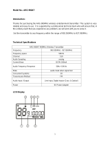
Fitness Entertainment Solutions
FM Transmitter
Manual and User Guide
ARG-OM-006-2014

Page 2
INSTALLATION INSTRUCTIONS:
Mounting the Transmitter - The ARG FM transmitter is a universal unit designed to be compatible with most makes
and models of televisions or audio devices. The transmitter can be mounted anywhere within the range of the length
of cable being used for the audio connection including on the TV/audio device. If mounting the transmitter on a
device, make sure not to cover ventilation grates or interfere with the functionality of the equipment. The transmitter
is designed with slots on the back that hook onto the included mounting bracket. For your convenience, screws with
wall anchors and hook-and-loop fasteners are provided to attach the mounting bracket to a variety of surfaces.
Attaching the Antenna – Place the rubber antenna into the receptacle marked “ANT” on the top of the transmitter
(Diagram #12) and tighten the screw until it seats into place. The antenna can be set to any angle or rotated 360
degrees to fit into available space.
Powering the Unit - Plug one end of the 9VDC power supply (included with the unit) into a 110V power outlet. Plug
the other end into the terminal on the side of the transmitter marked “DC/9V Input” (#8 on the diagram). When both
ends of the cord are plugged in, the transmitter will turn on.

Page 3
Connecting the Transmitter to an Audio Source - The transmitter has three types of audio input options. The type
of cable used to connect the transmitter to the TV or other audio source will depend on the type of audio output
terminals equipping the signal source device. You MUST set the transmitter to read the chosen input source.
Connection options are:
Analog Stereo Line Input (Diagram #9) – This input source allows connection to the audio device with either
the RCA analog audio output jacks or a headphone mini-jack/3.5mm stereo audio output jack.
IMPORTANT: Make sure to connect terminals on TV/audio device marked as audio OUTPUTS. Both audio
input and audio output connections can be made using these types of connectors/cables. Many newer
televisions DON’T have audio OUTPUT connections of this type and CANNOT be connected to the
transmitter using this method. If connecting to the RCA audio output jacks, use a cable (included) with
stereo RCA jacks (usually one red and one white or black) on one end and a 3.5mm stereo mini-jack on the
other. If connecting to a headphone jack or 3.5mm stereo mini-jack, use a cable that has 3.5mm stereo
plugs on both ends (conversion cable included). Connect the male/female RCA jacks to each other. The
3.5mm stereo plugs on either end of the combined cables will allow connection to TV/audio device. After the
connection has been made to TV/audio device, plug the other end of the cable into the port on the
transmitter marked “Line Input” (Diagram #9). NOTE: Do Not connect the transmitter to an amplified audio
source. The transmitter is manufactured with sensitive components that are designed to work with line-level
voltages Only. Connecting the transmitter to an amplified audio source will damage the unit and void the
warranty.
Digital Optical Input (Diagram #10) – Use this input selection if TV/audio device has a digital optical audio
output or S/PDIF or TOSLINK jack. This connection allows for the highest quality audio transmission and is
the preferred method if available. This connection requires the use of a fiber-optic or TOSLINK cable made
specifically for this type of connection. (This cable is available to purchase from ARG, #ARG-CA017 or from
any local electronics retailer.) One end of the cable is inserted into the jack marked “Optical Audio Output”,
“S/PDIF” or similar description on the TV/audio device. Insert the other end of the cable into the port on the
transmitter marked with “Optical Input” and the symbol that looks like this: XXXXX (Diagram #10). Make
sure the ends of the cable are securely connected to the ports on both ends. These plugs will usually “click”
into place when properly inserted. (NOTE: these cables are usually shipped with clear plastic protective end
covers which need to be removed before connecting the cable.)
Digital Coaxial Input (Diagram #11) – The output terminal for this connection looks like a standard RCA-type
jack and will be orange. A cable specifically designed to transmit digital audio signals is needed. (This
cable is available to purchase from ARG, #ARG-CA016 or from any local electronics retailer.) DO NOT use
a standard RCA cable since it will not have the proper shielding and may cause interference with other
electronic devices located in close proximity to the cable. Plug one end of the cable into the orange terminal
on the TV/audio device labeled “Digital Audio Output” or similar. The other end plugs into the white RCA
jack on the top of the transmitter marked “Coaxial Input”.
Note – DO NOT connect more than one audio source to the transmitter at a time. Connecting
multiple cables can cause permanent damage to the unit.
Setting the Audio Input Source - Set the input source on the transmitter to correspond to the chosen input
connection. This allows the transmitter to determine the type of audio signal to “read” and where to find it. Failure to
set the input source to match the connection will result in poor or no audio being sent from the transmitter. The input
setting is displayed on the input indicator (Diagram #14) by the number of decimals showing in the display. Set the
input source on the transmitter by pressing the “MODE” button (Diagram #6) in the lower left corner of the unit. Each
time the “MODE” button is pressed, the transmitter will toggle between the three input sources: Analog line (no
decimal lit); Digital coaxial (1 decimal lit); or Optical Digital (2 decimals lit).
Confirming Signal Acquisition – When properly connected to the TV/audio source (assuming the output for that
device has been set correctly) and the corresponding input source has been selected; the transmitter will detect the
audio signal automatically. Make sure the transmitter is receiving and has detected a usable audio signal from the
TV/audio source as displayed in the LCD window (Diagram #1). If the digits are steadily lit (NOT flashing), the
transmitter is receiving and has detected a good audio signal from the device. If the digits are flashing, the
transmitter has detected either a weak signal or no audio signal at all. If weak/no signal, check connections; check
the input setting on the transmitter; and check to make sure the TV/audio device is generating a usable signal. If the

Page 4
device is not sending a good signal, check to see if the volume level on the TV/audio source is adjusted too low. The
level should be set to approximately 75% of the maximum. Turn up the volume, then turn off the speakers on the
device by changing the setting through the on-screen menus (see owner’s manual for instructions.) If the problem
persists, contact the technical service department for TV/audio device or ARG for assistance.
Setting the Broadcast Frequency – Unlock the transmitter by pressing and holding the “LOCK” button until the lock
icon disappears from the display. The second digit in the frequency display will start to flash. (All 900MHz
frequencies begin with “9” therefore the cursor defaults to the second digit.) Enter the number on the keypad to set
the second digit for the chosen frequency. As digits for the frequency are set, the cursor automatically moves to the
right until all of the digits in the new frequency have been entered. The decimal point remains in the same place and
is always present; there is no need to enter the last digit as it is always zero (0). If the wrong number is entered,
move the cursor back by pressing the “OUTPUT DOWN” arrow. Then enter the correct number. Move the cursor
ahead by pressing the “OUTPUT UP” arrow. When all of the digits have been entered correctly, press the “ENTER”
button. (NOTE: Once the “ENTER” button has been pressed, the cursor will disappear. To change, press the “SET”
button to start over.) Finally, press the “MEMO” button to save frequency. The frequency MUST be saved by
pressing the “MEMO” button or it will have to be re-entered each time power is cut-off to the transmitter.
OTHER FUNCTIONS:
Changing the Output Level - This setting controls the loudness or volume level of the transmitter’s audio signal.
Use as an auxiliary volume control if the TV/Audio device has a fixed audio output that is either too high or too low.
The output level setting is displayed as two large numbers on the left side of the display, ranging from zero to 15.
Adjust the output level when the transmitter is in the “LOCK” mode (Lock icon shows in the display). Lower the
output level by pressing the “OUTPUT DOWN” arrow (#6) and increase by pressing the “OUTPUT UP” arrow (#7).
(Note: The factory output level is “08”. If the level is too low it will be difficult to hear the sound; if set too high, the
sound will be distorted and hard to understand.) This setting is also useful for evening out the volumes of different
televisions in a multiple device system as TV channels are broadcast at different volume levels.
LIMITED WARRANTY
Audio Resource Group, Inc. warrants all new ARG products to be free from defects in materials and manufacture for the warranty periods set forth
below. The warranty periods commence on the invoice dates of the original purchase. This warranty applies only against defects discovered within
the warranty period and notification to ARG must be given within 30 days after the date of discover of any nonconformity. Parts repaired or replaced
under the terms of this warranty will be warranted for the remainder of the original warranty period only. Product that fails after the warranty period will
be repaired or replaced at the current part and labor pricing after inspection by ARG and authorization from the customer. Audio Resource Group,
Inc.’s obligations under this warranty are limited as set forth below:
ARG-CV-FMT FM Transmitter Purchased Prior to 2014 2 Year
ARG-CV-FMT FM Transmitter Purchased after 1/1/2014 4 Years
Warranty only applies to the original buyer. Warranty is void if products have been damaged due to accident, misuse, abuse, improper service,
mechanical or electrical non-ARG, Inc. authorized modification. ARG, Inc. is not liable, without limitation to any person or entity, for any direct,
incidental, consequential damages or medical expenses caused by any use, defect, failure or malfunction of the product. This warranty does not cover
cosmetic damage of the product or if the serial number or model number affixed to the product has been removed, defaced, changed, altered or
tampered with. This warranty does not cover installation or signal reception problems. The terms of the warranty are governed by the laws of the state
of North Dakota, USA.
ARG will only accept returned products with prepaid shipping and a return authorization number. Contact ARG, Inc. at 888-468-4552 for a return
authorization number or for additional information.
Mail or Ship To:
Audio Resource Group, Inc.
Attn: Repair Department
405 Main Ave W Unit 4G
West Fargo, ND 58078
Phone: (888) 468-4552 Fax: (888) 373-4819 Email: repairs@argaudio.com
/