Page is loading ...

AIMB-769 Startup Manual 1
Before you begin installing your card, please make sure that
the following items have been shipped:
AIMB-769 ATX IMB
1 AIMB-769 Startup Manual
1 Driver CD (user’s manual is included)
2 Serial ATA HDD data cables
2 Serial ATA HDD power cables
1 I/O port bracket
1 jumper package
1 warranty card
If any of these items are missing or damaged, please con-
tact your distributor or sales representative immediately.
Note: Acrobat Reader is required to view any PDF
file.Acrobat Reader can be downloaded at:
www.adobe.com/Products/acrobat/readstep2.
html (Acrobat is a trademark of Adobe)
Standard SBC Functions
CPU: LGA775 Intel Core 2 Quad/Core 2 Duo/Pentium
Dual Core/Celeron
BIOS: AMI 16 Mb SPI BIOS
FSB: 800/1066/1333 MHz
Chipset: G41 with ICH7
System memory: Up to 4 GB with two 240-pin DIMM
sockets. Supports dual channel DDR3 800/1066 SDRAM.
Note: Due to the inherent limitations of PC architecture,
the system may not fully detect 4 GB RAM when
4 GB RAM is installed.
SATA II Interface: Four on-board serial SATA II connec-
tors with a data transmission rate of up to 300 MB/s and
supporting Advanced Host Controller Interface (AHCI)
technology.
•
•
•
•
•
•
•
•
•
•
•
•
•
•
AIMB-769 Socket LGA775 Intel® Core™2 Quad ATX
with VGA, 2 COM, Single LAN
Startup Manual
FDD interface: Supports one FDD
Serial ports: Two RS-232 serial ports with DC power (+5
V or +12 V) support for industrial applications.
Keyboard/mouse connector: Supports standard PS/2
keyboard and mouse.
Watchdog timer: 255 level timer intervals.
USB 2.0: Supports up to eight USB 2.0 ports.
VGA Interface
Chipset: Chipset integrated VGA controller.
Display Memory: Dynamically shared system memory
up to 352 MB.
Resolution: Up to resolution 2048 x 1536 @ 75 Hz
refresh rate.
Ethernet interface
Interface: 10/100/1000Base-T
Controller: LAN1: REALTEK RTL8111DL
Mechanical and Enviromental
Dimensions (L x W): 304.8 x 228.6 mm
Power supply voltage: +3.3 V, +5 V, ±12 V, 5 VSB
Power requirements: Maximum: +5 V at 1.76 A, +3.3
V at 2.28 A, +12 V at 4.7 A, 5 VSB at 0.19 A, (Intel Core
2 Quad Q9650 3.0 GHz, two 1GB DDR3 1066 MHz
SDRAM)
Operating temperature: 0 ~ 60° C (depending on CPU)
Weight: 0.5 Kg (weight of board)
Jumpers and Connectors
The board has a number of jumpers that allow you to con-
figure your system to suit your application. The table below
lists the function of each of the jumpers and connectors.
Connector/Jumper list
Label Function
CMOS1 Clear CMOS
JWDT1
Watchdog Timer Output Option
FDD1 FDD connector
LAN1_USB34 LAN1 / USB port 3, 4
VGA1 VGA connector
COM12 Serial port: RS-232
•
•
•
•
•
•
•
•
•
•
•
•
•
•
•
Specications
Packing List
For more information on this and other Advantech
products, please visit our website at:
http://www.advantech.com
http://www.advantech.com/eplatform
For technical support and service, please visit our
support website at:
http://www.advantech.com/support
This manual is for the AIMB-769 series Rev. A1
Part No. 2006076910 1st Edition,
June 2011
Specications

2 AIMB-769 Startup Manual
CN32
CN33
COM1 DC Power Switch
COM2 DC Power Switch
KBMS1 PS/2 Keyboard and Mouse connector
KBMS2
External Keyboard and Mouse connec-
tor (6-pin)
JFP1 Power Switch / Reset connector
JFP2
External Speaker/HDD LED/SMbus
Connector
JFP3
Keyboard Lock and Power LED
Suspend: Fast ash (ATX/ AT)
System On: ON (ATX/ AT)
System Off: OFF (AT)
System Off: Slow ash (ATX)
JCASE1 Case Open
PSON1 AT(1-2) / ATX(2-3)
VOLT1 Voltage Monitoring for Alarm Board
CPUFAN1 CPU FAN connector (4-pin)
SYSFAN1 System FAN connector (3-pin)
SYS
FAN2
System FAN connector (3-pin)
AUDIO1
Audio connector
FPAUD1
HD Audio Front Panel Pin Header
USB12 USB port 1, 2
USB56 USB port 5, 6
USB78
USB port 7, 8
SATA1 Serial ATA1
SATA2 Serial ATA2
SATA3 Serial ATA3
SATA4 Serial ATA4
ATX12V1
ATX 12V Auxiliary power connector
(for CPU)
EATXPWR1
ATX 24 Pin Main power connector (for
System)
SPDIF_OUT SPDIF Audio out pin header
BIOS1 SPI BIOS
JOBS1
Close: Enable OBS Alarm
Open: Disable OBS Alarm
IR_CON Infrared connector
CMOS1: CMOS clear function
Pins
Result
1-2 Keep CMOS data*
2-3
Clear CMOS data
* Default
JWDT1: Watchdog timer output option
Closed Pins
Result
1-2 No Function
2-3 *System reset when it is triggered.
* Default
PSON1: ATX, AT mode selector
Closed Pins
Result
1-2 AT Mode
2-3 ATX Mode*
* Default
The CD disc contains programs that will lead you through
the installation of various device drivers needed to take full
advantage of your motherboard.
The computer is supplied with a battery-powered realtime
clock circuit. There is a danger of explosion if battery is
incorrectly replaced. Replace only with same or equivalent
type recommended by the manufacturer. Discard used bat-
teries according to manufacturer’s instructions.
This device complies with the requirements in Part 15 of
the FCC rules. Operation is subject to the following two
conditions:
This device may not cause harmful interference.
This device must accept any interference received,
including interference that may cause undesired
operation.
1.
2.
Jumpers and Connectors
Jumpers and Connectors
Software Installation
Declaration of Conformity
Keep CMOS data Clear CMOS data
1 2 3
1 2 3
NC 1-2 closed System Reset 2-3 closed
1 2 3
1 2 3
AT Mode 1-2 closed ATX Mode 2-3 closed
1 2 3
1 2 3

AIMB-769 Startup Manual 3
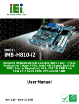
Figure 1: Board Layout - Jumper and Connector Locations
Jumper and Connector Locations
5 4 3 2 1
1 0 7 4 1
11 8 5 2
1 2 9 6 3
SPEAKER
SM_BUS
HDDLED
RESET
PWRSW
PWRLED & KEYLOCK
PCIe x1
PCI
PCIe x16
USB 5~8
SATA 1~4
JFP1~3
DIMM_A1
DIMM_B1
CPUFAN1
ATX12V1
SYSFAN1
FDD1
JWDT1+JOBS1
AUDIO1 USB12
LAN1_USB34
VGA1
COM12
KBMS1
KBMS2
JCASE1
PSON1
IR_CON
EATXPWR1
VOLT1
SPDIF_OUT
FPAUD1
SYSFAN2
CMOS1
CN32
CN33
/