Stratco Good Neighbour Installation guide
- Type
- Installation guide

INSTALL AT ION
GUIDE
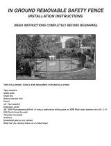
BEFORE YOU START
TOOLS AND HARDWARE REQUIRED
• Concrete
• Hack-saw
• Plumb Line
• Spirit Level
• Fencing Line
• Tape Measure
• Tin Snips
• Post Hole Digger
• Rivet Gun
• Drill and hex-head adaptor
GOOD NEIGHBOUR FENCING
Stratco Good Neighbour fencing is both strong and attractive. Its design allows clean and uncluttered lines to be enjoyed by neighbours
on both sides of the fence. Good Neighbour’s strength and style is achieved by using fence sheets that fit simply into profiled steel tracks
and posts. It is this simple design that makes Good Neighbour fencing so easy to install.
The wide range of colours, fencing profiles and accessories available, mean that a number of different looks can be achieved. Stratco
Good Neighbour fence sheet profiles include Superdek, Smartspan, CGI, CGI Mini and Wavelok. Wavelok is specifically designed for
fencing applications by Stratco, and features an identical appearance on both sides.
Ensure you have the correct components and tools before installing your fence. This installation guide should be read in conjunction with
the design guide. Gates should be installed before the fence is erected, to ensure a neat nish.
Good Neighbour

Refer to Design Guide for hole depth
Refer to Design Guide
for post intervals
String Line
Refer to Design Guide for hole diameter
Spirit level
Plumb
Line
8-14mm
off vertical
Concrete Chock up with
wooden blocks
Increase
Footing
depth by
100mm
Refer to
Design Guide
for depth
150
mm
150mm layer of
concrete mix,
agitated before
each subsequent
layer is poured.
Final layer
shaped to
slope away
from posts.
Accurately determine where the fence runs. (In some cases a
Surveyor may be required) and mark the position using a temporary
string line. Using the spacing information from the design
guide and the table below mark the post positions of the posts.
Figure 1.0
ESTABLISH THE FENCE LINE
3 Sheet 2 Sheet
1590
1630
1470
2350
2390
2170
3 Sheet SHS
2400
2440
2220
Wavelok, Superdek
CGI, CGI Mini
Smartspan
Sheet Inll Style 2 Sheet SHS
1640
1680
1520
FENCE POST SPACINGS
Table 1.0
GATE POST OPENINGS - Single 840mm - Double 3255mm
It may be necessary to use a shorter panel to obtain the required
fence run and for better aesthetics this shorter panel should be
positioned adjacent to a corner or gate post. Once marked, the
post holes can be dug. The use of a manual or mechanical auger
is recommended, especially for harder clay soils. The footing
dimensions can be found in the design guide. However, the last
three holes near a free end and for posts supporting a gate will
need to be 100mm deeper than the standard depth specied in
the design guide.
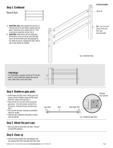
INSTALLATION OF GATES
The gate post holes should have already been dug. Fix the hinges
to the gate using the screws provided. Two hinges are required
per side. Fix the hinges to the SHS gate post, making sure the top
of the post is ush with the top of the gate. If the fence extends
past the gate, the post for the adjacent panel should be xed to
the SHS gate post.
Once the gate and posts are assembled, place the gate in position.
Chock up the centre of the gate with wooden blocks while using
a plumb line so that the post is between 8mm and 14mm o
vertical. This allows for the deections under the weight of the
gate. With the gate propped the posts can be concreted into place.
Preparing footings
Once the post has been positioned and propped into place,
the concrete can be mixed and poured. Prepare the Stratco
concrete mix as per the details on the bag and ll the hole with
approximately 150mm of concrete. Using a shovel or pole agitate
the concrete to remove air pockets. Add a further 150mm and
agitate again. This process should be repeated until the hole is
full. The top of the footing will need to be smoothed with a trowel
ensuring the surface slopes away from the post. No load should
be applied to the footing for at least 48 hours. Maximum concrete
strength may not occur for up to 28 days, so care should be taken
not to apply excessive force to the fence during this time.
Figure 2.0 Figure 2.1
All gates should be installed before the remainder of the fence is constructed.
GATE COMPONENTS AND ACCESSORIES - COMPONENTS ARE SUPPLIED WITH FIxINGS
Drop BoltButt Hinge Striker Plate Gate Latch
Pad Bolt
Gate Latch Handle

10x16mm
Self-drilling
screw
V-shaped
flashing in
CGI Mini track
38x25mm
rail
Fixing detail
Panel Height
Top Track
Bottom Track
Panel Width
Post
10x16mm
Self-drilling screw
Corner detail
Post fixing detail
Refer to Design Guide
Rotate sheet into position
Press top track into position
5 ripple self-drilling screws V-shaped flashing
V-shaped flashing38x25mm rail four 3mm rivets
10x16mm
Self-drilling
screw
V-shaped
flashing in
CGI Mini track
38x25mm
rail
Fixing detail
Panel Height
Top Track
Bottom Track
Panel Width
Post
10x16mm
Self-drilling screw
Corner detail
Post fixing detail
Refer to Design Guide
Rotate sheet into position
Press top track into position
5 ripple self-drilling screws V-shaped flashing
V-shaped flashing38x25mm rail four 3mm rivets
Notch cut
into ball cap
to sit on
corner post
Fixing corner
with SHS post
Fixing
corner
posts
10x16mm
Self-drilling
screw
V-shaped
flashing in
CGI Mini track
38x25mm
rail
Fixing detail
Panel Height
Top Track
Bottom Track
Panel Width
Post
10x16mm
Self-drilling screw
Corner detail
Post fixing detail
Refer to Design Guide
Rotate sheet into position
Press top track into position
5 ripple self-drilling screws V-shaped flashing
V-shaped flashing38x25mm rail four 3mm rivets
10x16mm
Self-drilling
screw
V-shaped
flashing in
CGI Mini track
38x25mm
rail
Fixing detail
Panel Height
Top Track
Bottom Track
Panel Width
Post
10x16mm
Self-drilling screw
Corner detail
Post fixing detail
Refer to Design Guide
Rotate sheet into position
Press top track into position
5 ripple self-drilling screws V-shaped flashing
V-shaped flashing38x25mm rail four 3mm rivets
FENCE INSTALLATION
Figure 3.0
Fence panels should be installed starting from a gate post, free
end or corner. If you are working on sloped ground and intend to
step or slope the fence see the sections on the following page for
the correct installation procedure.
Assemble the framework
Lay the posts down on the ground and insert the top and bottom
track. Fix the tracks using a 10x16mm screw on each side of
both ends, see Figure 3.0. The top track should be ush with
the top of the post, unless you are installing a screen top, in
which case the post will need to extend 300mm past the track. If
SHS posts are required, they should be xed to the fence at this
stage using three 10x16mm screws. Caps should be inserted on
top of the SHS posts to prevent water entering. When extending
from a concreted gate post the frame will need to be assembled
vertically in position.
Extending the fence
Assemble the second panel and x it to the rst using three
10x16mm self drilling screws, refer to Figure 3.1. Place the
fence into the footing holes. If you are using SHS posts, ensure
they are installed between the panels. Prop the fence into the
correct position and concrete the joined posts into place. Refer
to ‘Preparing Footings’ for the correct method of concreting
the posts. Frames should be assembled and added one at time,
concreting the footings as you install each frame.
When joining around a corner, the posts can be xed directly to
each other or both posts xed to an SHS coloumn, refer to Figure
3.2. The SHS method must be used if the design calls for the
panels to have SHS posts. Post caps and ball caps can be used on
a corner post, provided the bottom of the cap is cut to t on one
end, so the cap can sit ush.
Installing the sheets
After the concrete has been allowed to cure for at least 48 hours
the fence sheets can be installed. Working on one panel at a time,
take o the top track by removing the screws holding it in place.
The sheets can now be positioned in the frame. Each sheet should
be rotated into position as shown in Figure 3.3, ensuring the
correct sheet overlap. (refer to Figure 3.5) The top track can now
be reinstalled. Starting at one end and working down to the other,
push the track into position, making sure the track is rmly in
place. To minimise rattling, the sheets should be xed together
at the overlaps using a 3mm rivet midway up the sheet. In wind
speeds W41 and greater, fasten the sheets to the tracks at each
of the overlaps using 10x16mm screws.
Completing a CGI Mini Panel
For CGI mini, two V-shaped ashings are provided. The V-shaped
ashings slide into the tracks with the point of the ‘V’ to the
outside of the panel. A 38x25mm internal rail is installed on one
side. The rail is positioned in the gap between the sheet and post,
half way down the panel. Angle the rail into position and x the
rail to the post using a 10x16mm screw at each end. The sheets
are then xed to the rail using ve 10x20mm ripple self-drilling
screws per sheet ensuring it is fastened at each overlap. Sheets
should be xed together at the overlaps using four 3mm rivets
midway between the tracks and internal rail, see Figure 3.4.
Figure 3.3
Figure 3.2
Figure 3.1
Figure 3.4

SuperdekOVERLAP COVERAGE DETAILS FOR EACH SHEETING PROFILE
CGI
CGI Mini
Wavelok
Smartspan
Sloped Panel
Ball cap
Ball cap
300mm maximum
Step without post or ball cap
Step with post or ball cap
Ground distance
Sloped Panel
Ball cap
Ball cap
300mm maximum
Step without post or ball cap
Step with post or ball cap
Ground distance
Maximum 2/3 of
the fence height
Tapering occurs over the last two panels
Fence height
Tapering may be required at the free end of a fence. Refer to the
‘Design Guide’ to check if this is applicable to your situation. The
fence will need to be tapered down to at least two thirds of the
total fence height. Tapering is to occur over the last two panels.
Depending on your fence conguration a longer top track may
be required.
The end and middle posts should be cut to the required height.
The middle posts need to be cut halfway between the full fence
height and the end post height. Position the posts on the
ground and install the bottom tracks. Making sure the posts are
perpendicular to the bottom tracks, mark and cut the top tracks
to t. A longer track may be required in some congurations.
Once cut, the top tracks can be xed into the frame. Using the
method for a standard panel, concrete the posts into place.
The top of each sheet will need to be cut before installing. Use
the frame as a template to mark the sheets for cutting. Allow
a total of 10mm clearance to ensure the sheets t correctly in
the tracks. Avoid using an angle grinder to cut the sheets as
the swarf may stain the paint. Install the cut sheets as with a
standard panel installation.
Figure 3.5
Figure 6.0
Figure 4.0
Measure the ground distance between the holes and cut the
longer lengths of track to suit. (For slopes less than two degrees,
standard tracks and panels will suce). Assemble the frame as
per the previous panel and place the fence into position. Fix the
new post to the existing post and concrete the hole. Continue to
assemble the next frame.
To install the sheets, both the top and bottom of each sheet will
need to be cut to match the angle of the tracks. Use the frame as
a guide to mark and cut the lines on the sheets. Allow a total of
10mm clearance to ensure the sheets t correctly in the tracks.
Avoid using an angle grinder to cut the sheets as the swarf and
debris may stain the paint. Remove the top track on the panel
to install the sheets. With the sheets in place ret the top track
using the same method as with a standard fence. When using a
screen top extension, the lattice will also need to be cut to t.
This should be done after the sheets are installed.
Figure 5.0
A stepped frame should be installed using the same procedure as
with a standard fence panel except the post of the higher panel
will need to be longer. This will ensure correct post embedment
in the footing, refer to Figure 5.0. All tracks and sheets in a
stepped fence remain the same size as for a standard panel. If
you intend to use post or ball caps both joining posts will need
to be the same height in order to sit ush at the top. This is
because a post or ball cap is designed to sit over two adjoining
posts. A post inll should be used to slide in the open post end,
refer to the post inll section on the back page.
The best visual result will be obtained when the sheet overlap is arranged to face away from the most commonly viewed angle.
STEPPED FENCE
TAPERED END
SLOPING FENCE
The best visual result will be obtained when the sheet overlap is arranged to face away from the most commonly viewed angle.

Installation Order of Screen Top Components
Self-drilling screws
Top track
Lattice clips
Plastic lattice
Lattice track
Superdek or
CGI track
Lattice track
Self- drilling
screw
Lattice
clip
Slide lattice clips
inside track
Fasten post
extension in
position, using
one 10x16 self
drilling screw on
each side.
Fix one 10x16mm
self drilling screw
to post extensions
at mid-height,
offsetting 5mm
from centre.
Post Extension
Bracket
Post Extension
Remove screws
Top Track
Post
Post Extension
Bracket
Replace screws
Post Extension
Post
Lattice
Post Extension
Bracket
Installation Order of Screen Top Components
Self-drilling screws
Top track
Lattice clips
Plastic lattice
Lattice track
Superdek or
CGI track
Lattice track
Self- drilling
screw
Lattice
clip
Slide lattice clips
inside track
Installation Order of Screen Top Components
Self-drilling screws
Top track
Lattice clips
Plastic lattice
Lattice track
Superdek or
CGI track
Lattice track
Self- drilling
screw
Lattice
clip
Slide lattice clips
inside track
Fasten post
extension in
position, using
one 10x16 self
drilling screw on
each side.
Fix one 10x16mm
self drilling screw
to post extensions
at mid-height,
offsetting 5mm
from centre.
Post Extension
Bracket
Post Extension
Remove screws
Top Track
Post
Post Extension
Bracket
Replace screws
Post Extension
Post
Lattice
Post Extension
Bracket
Install the posts, tracks and sheets as detailed in the previous
section. Once the posts, tracks and fence sheets are in place, the
screen top components are ready to be installed.
Install the lattice track rst. Place the lattice track on top of the
existing Good Neighbour track and position it in the middle of
the highest point of the track. Fix the lattice track using two self-
drilling screws at even spacings.
With the lattice track is in position, the plastic lattice can now be
inserted into the lattice track.
The top track must now be installed. First, slide four lattice clips
into the top track, spacing them evenly. Push the top track onto
the lattice until the lattice ts snugly between the clips. Fix the
track to the posts using self-drilling screws, fasten on each side
at both ends as per the standard track.
This section covers the installation of a new screen top extension
to an existing Stratco Good Neighbour fence.
On one corner of the existing fence panel, where the post is
fastened to the top track, remove the two 10x16mm screws.
Slide the Good Neighbour post extension bracket down, between
the outside of the top track and the inside of the post.
Once the post extension bracket is in position, replace the
10x16mm self drilling screws into their existing holes, fastening
the post extension bracket to the top track.
Slide the post extension over the post extension bracket. Fasten
the post extension to the post extension bracket using one
10x16mm self drilling screw on each side.
Repeat the previous steps for all other post extensions along the
fence line. To install the Good Neighbour screen top componentry,
refer to the previous section.
Figure 8.3
Figure 8.2
Figure 7.0 Figure 7.2Figure 7.1
Figure 8.0 Figure 8.1
SCREEN TOP EXTENSION
SCREEN TOP INSTALLATION

Rivet
Ball cap
Post cap
Rivet Position
Fixing detail
Install ball or post cap Install ball or post cap
Insert post infill
Insert post infill
POST ON A FENCE END
POST ON A STEPPED PANEL
Post infill
Post caps or ball caps are an optional item that can be ordered with a new fence or
added to an existing Stratco fence. Caps must be installed upon completion of the
fence. Place the chosen cap on top of the two joined posts. Push the cap into position.
Drill one hole either side, through both the cap and post, then rivet into position, as
shown in Figure 10.0. Plain post caps can be cut in half when used on an end post.
Post inlls are used to tidy up an exposed post end on stepped panels or end panels
where post caps or ball caps are intended to be used. The inll will need to be cut to
the required length before being slid into the exposed post. The post or ball cap can
now be installed. The cap also prevents the inll from being removed.
Figure 10.0
Figure 9.0
MAINTENANCE REQUIREMENTS
POST INFILL
Fencing should not be located within 1000 metres of a marine environment or in
severe industrial or corrosive environments. For more information refer to “Selection,
Use and Maintenance of Stratco Steel Products” Brochure.
POST CAP INSTALLATION
BROCGNI
© Copyright April 04
A
ll brands and logos/images accompanied by ® or ™ are
trade marks of Stratco (Australia) Pty Limited.
stratco.co.nz
-
 1
1
-
 2
2
-
 3
3
-
 4
4
-
 5
5
-
 6
6


Stratco Good Neighbour Installation guide
- Type
- Installation guide
Ask a question and I''ll find the answer in the document
Finding information in a document is now easier with AI
Related papers
-
Stratco Good Neighbour® Installation guide
-
-
Stratco RGB-1 Operating instructions
-
-
-
-
-
-
-
Other documents
-
Barrette Outdoor Living 73003329 User manual
-
ALEKO FENCEPRA-HD Operating instructions
-
First Alert F3GHDG92X448PK Installation guide
-
 US Door and Fence G2GHDS33X32NWUS Installation guide
-
 US Door and Fence P254PUS Installation guide
-
 Veranda 135040 Installation guide
-
Edsal PC101 Assembly Manual
-
Everbilt 901180EB Operating instructions
-
 GLI Pool Products NE181F User manual
-
Sunnydaze Decor DSL-698 Installation guide


